THÈSE
En vue de l’obtention du
DOCTORAT DE L’UNIVERSITÉ DE TOULOUSE
Délivré par :Université Toulouse 3 Paul Sabatier (UT3 Paul Sabatier)Présentée et soutenue par
Chunyang NIE
Le 23/09/2016
Titre
:Etude de nanocristaux unidimensionnels confinés dans des nanotubes de carbone
Title :
The investigation of 1D nanocrystals confined in carbon nanotubes
ED SDM : Sciences et génie des matériaux - CO034
Unité de recherche :
UMR 5085 CIRIMAT - Centre Interuniversitaire de Recherche et d'Ingénierie des Matériaux UPR 8011 CEMES-CNRS - Centre d'Elaboration des Matériaux et d'Etudes Structurales
Directeur(s) de Thèse :
Dr. Emmanuel FLAHAUT, Dr. Marc MONTHIOUX
Rapporteurs :
Dr. Brigitte VIGOLO Institut Jean Lamour Université de lorraine Dr. Chris EWELS Institut de Matériaux Jean ROUXEL Université de Nantes
Autre(s) membre(s) du jury :
Prof. Alfonso SAN MIGUEL Université Lyon 1 Président Prof. Manitra RAZAFINIMANANA Université Paul Sabatier Examinateur
i
Acknowledgements
First and foremost I would like to thank my two supervisors Dr. Emmanuel Flahaut and Dr. Marc Monthioux for their guidance, support and assistance on the research during the last three years, especially the time they gave in the preparation of this thesis during the summer holiday.
I would like to thank Dr. Anne-Marie Galibert and Dr. Brigitte Soula for their help with my experimental work and the discussions with the experimental results.
I wish to acknowledge Dr. Chris Ewels and Dr. Brigitte Vigolo for taking their valuable time to be the Rapporteurs of the thesis, and their comments and remarks on the thesis. I also wish to acknowledge Prof. Alfonso San Miguel and Prof. Manitra Razafinimanana for participating in the jury.
I wish to acknowledge the grant of Chinese Scholoarship Council (CSC) for supporting my PhD study in France.
I wish to acknowledge Dr. Christophe Laurent, Dr Claude Estournes and all Nanocomposites Nanotubes de Carbone team: Dr. Alicia Weibel, Dr. David Mesguich and Professor Alain Peigney in Centre Inter-universitaire de Recherche et d'Ingénierie des Matériaux (CIRIMAT) and Dr. Etienne Snoeck in Centre d'élaboration de matériaux et d'études structurales (CEMES) for giving me the best ambiance and conditions in the lab during my PhD.
I also would like to express my big thank you to Sébastien Joulié and Florent Houdellier for their help with the training on the various kinds of transmission electron microscopes in CEMES, as well as their efforts to maintaining the good running of the microscopes (TEM). Without the microscopes, I could hardly finish my PhD study.
I would like to thank Laure Noé in CEMES for her help with the preparation of TEM grid at the beginning of my thesis and her help with the operation of CM30. Then I would like to thank Lucien Datas in Centre de microcaractérisation Raimond Castaing for the help with taking beautiful TEM images of my samples with the powerful JEOL JEM-ARM200F.
I would like to thank David Neumeyer in CEMES for spending time helping with the sulfurization experiments, discussing with my experiment results and giving me good advises.
ii
processing the holograms and explaining me the results. Though nothing interesting has been found thus far, it was a good exploration and experience for me.
I would like to thank Dr. Escoffier Walter and his PhD student Yang Ming in Laboratoire National des Champs Magnétiques Intenses (LNCMI) and Dr. Benjamin Lassagne in Laboratoire de Physique et Chimie des Nano-objets (LPCNO) for their help with the measurements of electrical conductivity of my samples. Though the measurements are still in processing and the full datas are not possible to be represented in this thesis, their work is valuable to my PhD project.
I would like to thank all my colleagues in CIRIMAT (Pierre Lonchambon, Jean François Guillet, Thomas Lorne, …) and in CEMES (David Reyes, Juan Du, Rongrong Wang, Tian Wang, Tingting Xiao, Xiaoxiao Fu, … ) for their help and the good time we spent together.
Finally, I would like to thank my family for their support and encourage during all these years.
Amicalement,
Chunyang Toulouse, France
iii
Table of contents
Acknowledgements ... i
Table of Contents ………..iii
List of Abbreviations ... v
General Introduction ... 1
Chapter 1 General Introduction to Filled Carbon Nanotubes ... 3
1.1 Carbon Nanotubes ... 4
1.2 Filled Carbon Nanotubes ... 6
1.2.1 A Glimpse at the History of Filling CNTs ... 6
1.2.2 The Motivations with Filling CNTs ... 9
1.2.3 Filling Strategy ... 10
1.2.3.1 In Situ Filling Route ... 10
1.2.3.2 Ex situ Filling Route ... 13
1.2.3.2.1 Previous Opening of the Tubes ... 13
1.2.3.2.2 Filling by Gas Phase Methods ... 14
1.2.3.2.3 Filling by Liquid Phase Methods ... 15
1.2.4 Species Encapsulated within CNTs ... 19
1.2.4.1 Atoms (Isolated, or as Chains) ... 20
1.2.4.2 Molecules (Isolated, or as Chains) ... 21
1.2.4.3 Pure Elements (as Nanowires or Nanoparticles) ... 23
1.2.4.4 Compounds (as Chains, Nanowires, or Nanoparticles) ... 24
1.2.5 Filling Mechanisms... 25
1.2.6 Behaviors, Properties and Applications ... 28
1.2.6.1 Peculiar in-Tube Behavior (diffusion, coalescence, crystallization) ... 29
1.2.6.2 Electronic Properties (Transport, Magnetism and others) ... 33
1.2.6.3 Applications ... 38
1.3 Conclusion ... 39
References ... 40
Chapter 2 Investigation on the filling mechanisms of DWCNTs with foreign phases and of the resulting peculiar structures of the latter ... 59
2.1 Introduction ... 59
2.2 Preparing/gathering host CNTs and BNNTs ... 60
2.2.1 CCVD synthesis of DWCNTs/FWCNTS ... 60
2.2.2 Extraction of DWCNTs/FWCNTs ... 61
2.2.3 Nanotubes from external suppliers ... 63
2.3 Synthesis of X@CNTs or X@BNNTs (X = halide or iodine) ... 67
2.4 Electron microscopy characterization on the X@CNTs and X@BNNTs ... 69
iv
2.5.1 Encapsulated NiI2 ... 78
2.5.2 Encapsulated iodine ... 82
2.5.3 Summary regarding the various structural states of encapsulated iodine ... 92
2.6 Filling mechanisms ... 94
2.6.1 Physical and chemical properties of the filling materials ... 94
2.6.2 Discussion ... 97
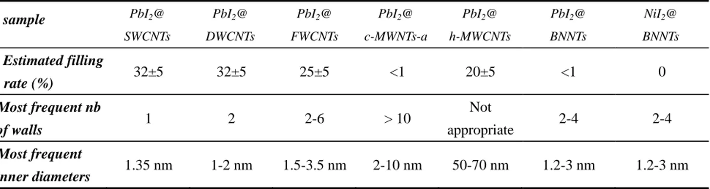
2.6.3 Influence of the properties of host CNTs on the filling rate ... 101
2.7 Conclusions ... 103
Chapter 3 In situ chemistry in X@DWCNTs ... 109
3.1 Introduction ... 109
3.2 In situ sulfurization of PbI2@DWCNTs ... 109
3.2.1 Methods ... 109
3.2.2 Results and Discussion ... 111
3.3 In situ H2-reduction ... 117
3.3.1 Methods ... 117
3.3.2 Results and Discussion ... 118
3.3.2.1 In situ reduction of FeI2@DWCNTs ... 118
3.3.2.2 In situ reduction of NiI2@DWCNTs ... 123
3.4 In situ fluorination ... 132
3.4.1 Methods ... 132
3.4.2 Results and Discussion ... 133
3.5 Conclusion ... 139
General Conclusions and Perspectives ... 143
Appendix METHODOLOGY ... 151
A.1 Principles of TEM Imaging and Related Techniques ... 151
A.2 Methodology for the Image Simulation and Structure Modelling of Confined Foreign Phases . 157 Résumé en Français ... 159
Publications: ... 185
v
List of Abbreviations
ADF Annular dark field
BF Bright field
BNNTs Boron nitride nanotubes
CCVD Catalytic chemical vapour deposition
c-MWCNTs Concentric multi-walled carbon nanotubes
CNTs Carbon nanotubes
DWCNTs Double-walled carbon nanotubes
EELS Electron energy loss spectroscopy
FWCNTs Few-walled carbon nanotubes
HAADF High angle annular dark field
HRTEM High-resolution transmission electron microscopy
MWCNTs Multi-walled carbon nanotubes
c-MWCNTs-a Concentric multi-walled carbon nanotubes prepared by arc discharge
h-MWCNTs Herringbone multi-walled carbon nanotubes
PDF Pair distribution function
STEM Scanning transmission electron microscopy
SWCNTs Single-walled carbon nanotubes
TEM Transmission electron microscopy
X-EDS X-ray energy-dispersive spectroscopy
XPS X-ray photoelectron spectroscopy
XRD X-ray diffraction
1
General Introduction
Carbon nanotubes (CNTs) have attracted since 1991 a lot of attention from the scientific community mainly due to their remarkable physical properties. Most of the current interest is focused on the practical applications of CNTs. To actually use them in various applications, it is often necessary to modify the CNTs in various ways. One of these ways may be to fill them with foreign materials, so that the properties of the host CNTs would be modified due to the interaction with the filling material. Moreover, the templating effect provided by the inner elongated cavity of - CNTs can enforce the inserted materials to adopt a 1D morphology, thus making filling CNTs an alternative route to synthesize 1D nanocrystals/nanowires. Meanwhile, when foreign materials are confined within a limited space, chances are high that deformation of the lattice structure, or even formation of new structures may occur for the encapsulated materials. These possibilities to induce new behaviours or new properties are more likely to occur if the inner cavity of the nanotube is smaller. Therefore, filling single-wall CNTs (SWCNTs) or double-wall (DWCNTs) – which may have an even smaller inner diameter – should be preferably considered as their inner cavity is typically below ~2 nm.
Filling CNTs to prepare X@CNTs hybrids can be achieved by various means and among them the molten phase method is widely employed due to the possibility for high filling rates, simplicity and versatility. Filling CNTs with a liquid is driven by the capillary force generally described by the Young-Laplace equation, but the detailed mechanisms involved in the capillarity filling of CNTs are not clear yet because they depend on different parameters such as the requirement of opening of the nanotubes, the inner diameter and the fact that the wetting properties of CNTs should depend on the texture of the inner tube (concentric tubes, or the so-called herringbone organization).
Even if very simple on the principle, not all compounds can be introduced by the molten phase method due to intrinsic incompatibility (chemical, physical) between the material and the CNTs, or technical limitations of the experimental procedure. To overcome this problem, the strategy of applying post-treatments to CNTs filled with a precursor of the target material can be used. In this way, the synthesis of, for example, metals or sulphides (otherwise generally presenting drawbacks fatal to filling such as poor wetting of CNTs, possible chemical reaction with the host tube, too high
2
melting point… if tentatively directly inserted) nanowires, may be prepared. This work thus aimed to better understand the basics of filling nanotubes with molten materials as well as the mechanisms of chemical reactions performed in situ in the inner cavity of the nanotubes. With such a goal, metal iodides have been selected as model compounds because they combine well-matching physico-chemical properties with the high electronic density of iodine, making this element particularly easy to image by high-resolution transmission electron microscopy (HRTEM), a central tool in this work.
Investigations on the properties of individual X@CNT hybrids are quite appealing since the properties of the inserted nanocrystals are expected to differ from that of the bulk material because of their likely different structure, high anisotropy, and surface atoms/core atoms ratio far different from ~0. These potential new properties may also be transferred to the CNTs. Unfortunately, examples of characterisation of such nanostructures is still relatively scarce in the literature, possibly because the facilities and devices for measuring properties of filled CNTs at the microscopic level are not so accessible, or more likely because it is difficult to ensure that the measured nanotube is indeed filled.
This PhD manuscript thus consists of 3 chapters. Chapter 1 is a general introduction to the filling of carbon nanotubes, describing the state of the art of filling strategies, as well as reporting some examples of properties and applications of filled CNTs. Chapter 2 reports our investigations (i) of the filling mechanisms when using the molten phase method by considering a variety of filling halide materials (with a focus on iodides and iodine) as well as a variety of host nanotubes (with a focus on DWCNTs) with molten compounds and (ii) of the resulting peculiar X@CNT hybrid nanostructures, with the help of HRTEM, and scanning transmission electron microscopy (STEM) techniques, as well as local probe electron energy loss spectroscopy (EELS). Chapter 3 deals with three different attempts of in situ transformations of selected X@DWCNTs: (i) the in situ
sulfurization of PbI2@DWCNTs, (ii) the in situ H2-reduction of FeI2@DWCNTs and
NiI2@DWCNTs, and (iii) the in situ fluorination of FeI2@DWCNTs. Finally, a general conclusion
summarises our results and present our perspectives, in particular the work in progress related to the characterisation of X@DWCNTs hybrids, which could unfortunately not be included in this manuscript.
3
Chapter 1
General Introduction to Filled Carbon Nanotubes
In 1991, a paper published by Iijima in Nature [1] presenting unambiguous proof of multi-walled carbon nanotubes (MWCNTs) which was discovered in the hard deposit growing at the cathode during electric arc experiments to produce fullerenes had a huge impact on the scientific community back then. Before that, most scientists did not give a second thought to ‘nano’. Ironically, MWCNTs had already been known as early as 1950s [2, 3], and for decades they were merely regarded as hollow carbon filaments - the undesirable byproducts to remove from the processing in the coal and steel industry and also in the nuclear industry. Subsequently in 1993, another work by Iijima with Ichihashi as the co-author reporting the synthesis of single-walled carbon nanotubes (SWCNTs) was published [4]. It is interesting to point out that another team, from IBM, California [5] also reported the formation of SWCNTs at the very same time as the Japanese team. Since then, scientists have devoted their attention to the research on the unique properties of CNTs and the exploration of their applications.
Up to now, many aspects concerning CNTs have been developed maturely. For instance, the synthesis routes for large-scale and diameter-controlled production are well established and supplied commercially, theories to predict various properties of CNTs are well supported by experimental results. Therefore, more and more attention are paid to the actual integration of CNTs in devices and their incorporation in advanced materials and crafts of practical interest. Unfortunately, many challenges with respect to the poor dispersibility, solubility, etc. of CNTs are needed to overcome. One alternative is to modify the CNTs in various ways including adding groups to the surfaces or inserting materials into the cavity and so on. Through the modification, more versatile CNTs are obtained and exhibit more fascinating properties, which can be considered as a third-generation of carbon nanotubes. This new generation of CNTs is named “meta-nanotubes” which is classified into five main categories [6]: functionalized nanotubes (denoted as X-CNTs), decorated nanotubes (denoted as X/CNTs), doped nanotubes (denoted as X:CNTs), filled nanotubes (X@CNTs) and heterogeneous nanotubes (X*CNTs), where X refers to the foreign components associated with nanotubes and which can be chemical functions, phases, atoms or molecules. Compared with the other four kinds, filled nanotubes can be seen as a complement to the full exploitation of the spaces in nanotubes as it only deals with inner cavities. In this manuscript, the
4
subject is focused on the synthesis of X@CNTs, the mechanism of filling CNTs and some related properties of X@CNTs.
1.1 Carbon Nanotubes
To understand the structure of carbon nanotubes, it is better to begin with the simplest one – single-walled carbon nanotubes (SWCNTs). Let us image rolling a graphene sheet, a single-atom-thick hexagonal lattice of sp2-hybridized carbon atoms, into a cylinder and then adding two hemifullerenes to the two ends of the cylinder to close it. Of course, there are many ways to roll up the graphene into a cylinder thus the indices proposed by Hamada et al. [7] to describe the various kinds of SWCNTs are quite useful. As illustrated in Fig 1.1, if the cylinder is formed by
overlapping the O atom with the A atom in another ring in the graphene, the helicity vector which is equal to OA can be decomposed into two vectors parallel to the graphene lattice vectors
and described in Eq. 1.1:
= n + m (1.1) where n and m are Hamada’s indices counting the number of hexagons crossed by each vector and | |= | |= 2.46 = a (the graphene basis [8]). Hence a (5, 2) SWCNTs is formed in Fig 1.1.
Fig 1.1 - Illustration of how to define a SWCNT by rolling up a graphene sheet with Hamada’s indices.
When n is equal to m or n is nil or m is nil, in which case is parallel to one of the symmetry planes of the graphene, two specific nanotubes can be generated: armchair (n=m) and zigzag (n or
5
m=0). Both types of nanotubes possess mirror symmetry and thus are achiral while those tubes with nm0 are called chiral (Fig. 1.2).
Fig. 1.2 - Examples of three types of SWCNTs, from left to right are armchair, zigzag and chiral, respectively [9].
If we roll several stacked graphene sheets into a cylinder, then a multi-walled carbon nanotube (MWCNT) with concentric texture is obtained. In the case of two rolled graphene sheets, a double-walled carbon nanotube (DWCNT) is formed which can be seen as the intermediate between SWCNTs and MWCNTs that possesses the advantages of both CNTs (Fig. 1.3).
Fig. 1.3 - TEM images of three types of CNTs, from left to right are SWCNTs, DWCNTs and concentric-type MWCNTs, respectively [4, 9, 10].
6 1.2 Filled Carbon Nanotubes
1.2.1 A Glimpse at the History of Filling CNTs
When MWCNTs became the research focus for physicists, chemists, material scientists and even mathematicians, some attention was paid to the possibility of filling the inner cavity of MWCNTs with various foreign elements or compounds–mainly metals aiming at the synthesis of nanowires. Theoretically, driven by the capillary force the filling can be achieved considering the MWCNTs as nanostraws with diameter in the range of 10-50 nm and the calculations based on Young-Laplace equations predicted the threshold of surface tension for the inserted materials [11, 12] although the validity of this approach in this case can be discussed. In this context, several examples of filling arc-produced MWCNTs were reported in 1993 [13-17]. However, the filling scarcely occurred over length higher than 100 nm for most filled tubes, possibly related to the fact that once the inner hydrostatic pressure equilibrates the outer pressure the filling event stops. Meanwhile, a two-step method including a pre-opening process using oxidizing gas phases [13, 15] or oxidizing acids [18] and then a filling process was proposed. However, studies involving the two-step method came with some problems, such as low filling rates, limited number of species as filling materials, or irreversible damages to the nanotubes. To overcome these drawbacks, in situ filling attempts were made which were approached by mixing metal-containing compound like metal oxide [17] or metal carbide [14] with the graphite anode within the arc reactor. In this way, the compounds were encapsulated inside MWCNTs during their growth process. When pure transition metals (Ni, Co, etc.) were selected, SWCNTs were unexpectedly produced [4, 5], making a breakthrough for the scientific community.
Compared to MWCNTs, the diameters of SWCNTs are more than one order of magnitude smaller (typically 1.4 nm) which can be seen as truly nano-world objects. Consequently, the interest in filling SWCNTs is much greater than that previously shown for filling MWCNTs. In spite of the efforts made by researchers from different laboratories, it took five years after the first filling of MWCNTs for the first successful encapsulation of Ru by SWCNTs to be published by University of Oxford [19] (Fig.1.4a), immediately followed by the discovery of SWCNTs filled with fullerenes
7
(‘peapods’) resulting from the collaboration between University of Pennsylvania and CEMES in France [20] (Fig.1.4b). In the former case, a mild process with concentrated HCl solution was used to open the SWCNTs first and then RuCl3 compound was deliberately introduced into SWCNTs via
a wet chemistry method; a subsequent reduction in a H2 stream was carried out in order to get Ru
metal. However, the displayed transmission electron microscope (TEM) images (Fig. 1.4a) were confusing as isolated filled SWCNTs instead of ropes of SWCNTs are hardly seen thus making it difficult to tell whether the filling occurred in the cavity of SWCNTs or in the interstitial space in the ropes, as well as to tell whether the ends of tubes were open. Later, the Oxford team modified the filling conditions by soaking the pristine SWCNTs into molten mixtures of KCl-UCl4 or
AgCl-AgBr [21]. Surprisingly, continuous crystals filling the tubes were found in abundance for both mixtures as evidenced by high resolution TEM (HRTEM) images. Subsequently, various halides including lanthanide halides LnCl3 [22], alkali iodides [23-27], ZrCl4 [28], AgClxI1-x [29] etc.
were attempted to fill SWCNTs or DWCNTs by this team. In 2001, Mittal et al. [30] performed the filling of SWCNTs with chromium oxide at room temperature, which is the first example of filling SWCNTs with oxides. Another example of Sb2O3-filled SWCNTs [31, 32] was reported by Oxford
in the same year. Following the two studies, other oxides and hydroxides (KOH and CsOH [33]) were also introduced into SWCNTs, sometimes with a quite high filling rate (e.g. 80-90% for PbO). However, as most oxides have low solubility in harmless solvents or high melting point, they are not as favorable as halides for filling. Nitrates, on the other hand, were also popular compounds for filling SWCNTs. One interesting example reporting SWCNTs filled with double-helix chains of iodine by Fan et al. [34] should be noted here, which was the pioneering work on filling CNTs with atoms. Intriguingly, in their previous study [35], the authors only investigated the effect of iodine-doping on SWCNTs materials, not realizing that the molten iodine can help opening the ends of SWCNTs thereby entering the SWCNT cavities. Based on this research, a similar structure was assumed for encapsulated Cs chains prepared later [36]. However, due to the limited resolution of TEM achieved at that time, iodine chains were not so unambiguously observed and the following studies using similar methods as in [34] more or less focused on the charge transfer between iodine and CNTs through other characterizations rather than imaging iodine chains directly [37-40]. It is only in 2007 that Guan et al. demonstrated single, double or even triple chains of iodine confined in SWCNTs by means of HRTEM technique [41]. Recently, the formation of other atom chains (sulfur
8
chains [42] and selenium chains [43]) encapsulated within SWCNTs or DWCNTs was also reported.
The story for peapods (C60@SWCNTs) is different. Though reported in the same year as
RuCl3/Ru@SWCNTs, they were not deliberately synthesized but were actually by-products from
the purification and annealing treatments on raw SWCNTs materials produced from the pulsed laser vaporization method (PLV) [20, 44-46]. These spontaneously formed peapods during the post synthesis process were questioned for a while, as the spontaneous formation could also be achieved during the synthesis of SWCNTs within plasma when arc discharge method was used [47, 48]. As a result, attempts to prepare C60@SWCNTs with a controlled synthesis were made by annealing the
mixture of acid-treated SWCNTs and fullerenes in vacuum which led to much higher filling yield of 50-100% [49-53] than that for peapods produced during regular SWCNTs synthesis (less than 10%) [46, 48].
Fig. 1.4 - TEM images of the two firstly reported examples regarding to filling SWCNTs in 1998 (a) Ru@SWCNTs, the metal Ru was reduced from the initially introduced RuCl3 [19]; (b) C60@SWCNTs (peapods) [20].
Beyond these experimental fillings, some ‘virtual’ filling examples are simulated on the basis of theoretical calculations. For instance, by modeling the confinement of water in SWCNTs, new ice phases not seen in bulk ice and a solid-liquid critical point are suggested [54]. Likewise, the insertion of Na and K atoms [55] or DNA molecules [56], the formation of metals nanowires or semiconductor nanowires within SWCNTs [57-62] and related properties are predicted using ab initio molecular dynamics simulations or other simulations. It should be pointed out that the fillings of these materials are actually performed either with MWCNTs without exhibiting intriguing behaviors or with SWCNTs/DWCNTs but nanowires are not obtained in that case.
Apart from introducing solid and liquid into CNTs, filling CNT with gases is also reported but considered as a controversial issue. Those works dealing with the filling of hydrogen are inspired by
9
the potential applications of CNTs as H2 containers [63, 64], while other gases are rarely attempted
for filling but Xe [65], O2 and N2 [66]. However, several possible sites including inner cavities in
CNTs contribute to the absorption of gas molecules and the exact location of the absorbed molecules is unable to be demonstrated so far. Therefore, details about the filling with gases will not be introduced in following sections.
1.2.2 The Motivations with Filling CNTs
What makes filling CNTs so special? Firstly, the inner cavity of nanotubes can act as a template or ‘nanomould’, and/or as a ‘nanoreactor’ (i.e. for the chemical transformation of an inserted material) for the synthesis of nanomaterials. Due to the confinement situation in CNT cavity, inserted materials are enforced to adopt the one-dimensional (1D) morphology. Especially, the templating of SWCNTs or DWCNTs can promote the formation of 1D materials with very small diameter and high aspect ratio. Furthermore, the encapsulation of CNTs is found to be a shelter for the contained materials from reactions with the surrounding medium, typically oxidation by contact with air, as well as dissolution of the confined material in aqueous or non-aqueous solvents. In this regard, filling CNTs is considered as a possible approach to obtain nanowire-like materials that could never exist if not encapsulated. Indeed, it has been demonstrated that metallic nanowires of 1 nm in diameter would rapidly turn into oxide nanowires or would even possibly collapse when attempting to remove the carbon sheath from filled SWCNTs [67]. In both cases, the possibility of losing any peculiar property is high. In general, phase growth within a very confined space offers a chance to enforce and stabilize new combinations of chemical elements, novel crystal structures for regular chemical phases and to deform and stress lattices within regular structures.
Once new 1D nanomaterials are formed, new, alter or enhanced physical properties are anticipated for them. The latter expectation arises from the stabilization of otherwise impossible new chemical compositions, structures or morphologies. Typical examples includes (i) the ballistic transport behavior from the one-dimensional structures, which prevents electron scattering; (ii) the immense surface-atom to core-atom ratios, which may even reach an infinite value, (e.g. all the atoms of the structure can effectively be ‘surface atoms’), and (iii) the protection by the carbon shell from the disturbance of absorbed molecules on the surface. Representative expectations and
10
achievements benefit from nanowires prepared from magnetic elements or compounds and charge-transfer electronic interactions with the encapsulating graphene lattice and the guest materials.
In an opposite manner, in case the encapsulated phases do not exhibit any peculiar property, filling can then be utilized as a special approach for external reactants to access the filling materials, thus controlling the behavior of the latter by controlling the interaction kinetics with the surrounding medium. However, there is a risk that the chemical reactivity of the filling material may be more or less inhibited despite of the nanosize as a result of the presence of the carbon sheath. On the other hand, this modified behavior relating to chemical reactivity may occur in a positive manner for some applications, for example, slowing down diffusion kinetic and/or chemical reactivity may be very valuable in fields such as chemical catalysis, drugs or pesticide delivery, and so on.
Overall, new phases, new structures, new properties, and/or new behaviors are very likely to be induced by confining foreign materials in CNTs. More specifically, any of these features will be more likely if the size of the tube cavity is smaller. Hence, filling SWCNTs and DWCNTs whose inner cavity is generally below 2 nm is preferably considered for scientists and the examples given below are mainly related to filling SWCNTs/DWCNTs.
1.2.3 Filling Strategy
Generally speaking, there are two possible routes for filling CNTs at present, in-situ filling and ex-situ filling. For ex-situ filling route, guest materials can be introduced into CNT cavities as a liquid or vapour depending on their physical properties including solubility, melting point, boiling point and of course, decomposition temperature, which should not be reached. Thus, two popular methods employed during the ex-situ filling process are the gas phase method and the liquid phase method. Details about the filling strategy are described in the following sections.
1.2.3.1 In Situ Filling Route
11
a one-step synthesis procedure. In this way, the nanotube sheath remains intact and, depending on the synthesis process, closed (for arc-prepared CNTs) or opened at one end only (for CCVD-prepared CNTs) are formed, consequently isolating as much as possible the encapsulated material from the surrounding post-synthesis environment. Meanwhile, elements with high melting point or high surface tension which are unfavorable for filling by wetting methods (see next) are sometimes allowed to fill CNTs through in-situ routes.
In fact, in-situ filling mainly occurs spontaneously during the synthesis of MWCNTs, either during the electric arc process [68] or the CCVD process [69]. For the latter, specific conditions are required to trap and encapsulate the excess metal catalyst which is critical for growing nanotubes, thereby making it limited. Because catalysts for carbon formation are typically transition metals such as Co, Fe and Ni, metal-filled MWCNTs can be synthesized this way (Figs. 1.5 a and b). Examples involving encapsulation of other materials such as Mg3N2 [70],Sn [71], Ge [72], Cu [73]
and Fe3C[74] by the CCVD method can also be found in the literature. However, since most
catalysts used for CNTs are ferromagnetic metals, in this sense this method can be taken as an efficient way to produce ferromagnetic nanowires encapsulated in nanotubes [69, 75-78] otherwise difficult to obtain (see next).
In an electric arc process, first the powder of the desired element or the mixture of it with graphite is compacted into a coaxial hole drilled within the graphite anode, then the electric arc is run under conditions similar to that used to produce fullerenes and finally partially filled MWCNTs are usually collected as a cathode deposit. However, the efficiency and control of the filling process is lower than for the CCVD-related method, possibly arising from the huge temperature gradients in arc-related processes. In addition, early works dealing with in situ filling by electric arc method reported that the presence of sulfur played a key role in the formation of filled nanotubes [68, 79]. In contrast to the CCVD-based method, electric arc method is hardly able to achieve the encapsulation of transition metals within MWCNTs though some rare examples may be found [79]. On the other hand, many other elements such as Yb, Dy or Ge, and so on, can be successfully introduced into MWCNTs during the electric arc process (Fig. 1.5 c and d). Therefore, the CCVD method and the electric method conveniently complement each other.
Regardless that many materials can be confined in MWCNTs via in situ filling by considering either methods, multi-element compounds involving oxide, salts, etc. are not permitted to be
12
inserted into nanotubes because of the restricted number of species able to play the role of a catalyst for the CCVD process or because of the high temperature involved for the electric arc process, which is a major disadvantage. Another disadvantage is that filling SWCNTs by this route is scarcely possible and when it is, a small amount of filled nanotubes are obtained. Only a few examples involving the electric arc process are found in the literature. One is the incidental discovery of peapods [20] described above and the other one is the encapsulation of Bi in SWCNTs by mixing a few percent of both Co (as catalyst) and Bi with the graphite anode, as previously described [80]. To overcome these drawbacks exhibited by in situ filling, specifically the challenge for filling SWCNTs, ex situ processes have thus emerged, as we will see in the next section.
Fig. 1.5 - (a) HRTEM image of a α-Fe filled MWCNTs prepared by CCVD process [81]; (b) TEM image of Co nanowires encapsulated inside nanotubes prepared by CCVD process. The inset displays an encapsulated nanowire and the corresponding SAED pattern showing the presence of f.c.c.-Co structure. [75]; HRTEM images of filled CNTs produced by arc-discharge when a 99.4% graphite anode is doped with: (c) Ge and (d) Yb. In the case of Ge (c), the filling material is polycrystalline and encapsulated in only 2 or 3 graphitic layers. Pure Ge microcrystals in a <110> projection can be seen on the left and right parts of the nanowire and typical microtwins and stacking faults of the <111> dense atomic layers are frequently observed [79].
13
1.2.3.2 Ex situ Filling Route
Ex situ filling is a very versatile route as it possibly allows nearly any kind of material to be inserted into nearly any kind of nanotubes. During this process, the capillary property of nanotubes is fully exploited. Various ex situ filling means employed in the literature will be described in detail subsequently. As illustrated, one-step or multi-step procedures are carried out to realize the ex situ filling, not mentioning the final cleaning step by means of washing or heating in dynamic vacuum which is necessary for all ex situ methods to remove the non-encapsulated material.
1.2.3.2.1 Previous Opening of the Tubes
Unless the initial CNTs prepared under certain specific conditions are thus naturally opened or single-step filling procedures are performed, the first requirement for ex situ filling of nanotubes is to open them. To achieve this, two ways are widely employed including (i) thermal treatments in oxidizing gas atmosphere (air, O2, O3 or CO2) [13, 82, 83] or (ii) reaction with liquid reactants that
are oxidizing for polyaromatic carbon materials, typically, acids such as HNO3, H2SO4, or a mixture
of both [18]. Other oxidizing agents like supercritical water [82], KMnO4, H2O2 [84], Br2 [85],
HF/BF3 mixture, aqueous OsO4, OsO4-NaIO4 [86], or activation with alkali hydroxide [87] are also
reported in literature. Beyond the two main ways, mechanical ball milling or electrochemical treatment can also open the CNTs. However, liquid phase oxidation intends to generate residuals that may more or less cover the nanotubes, hence impeding the subsequent filling or characterization. In this regard, gas phase oxidation is generally preferred. Meanwhile, these oxidizing treatments can also be used to purify, functionalize or shorten CNTs.
Given that the graphene lattice possesses comparatively high inertness toward chemical oxidation, opening normally occurs at the location of structural defects or high strain. For MWCNTs, pentagons are obviously found at their tips which enables the opening, while the wall structure is almost impossible to be opened because the possibility that the defects from each graphene wall are located at the same site where the opening takes place are extremely low. On the contrary, the tips and the side walls of SWCNTs are both potential sites for opening which are proved by TEM investigation or other ways in some early studies [88].
14
1.2.3.2.2 Filling by Gas Phase Methods
Filling nanotubes via gaseous phase is carried out by heating an evacuated and sealed Pyrex or quartz vessel that contains the previously opened nanotubes together with the desired filling material up to the vaporization or sublimation temperature of the filling material, or slightly above. Materials with low vaporization or sublimation temperature (C60, S, Se, etc.) are normally inserted
into nanotubes in this way [42, 45, 89]. For filling materials exhibiting high electronic affinity with the graphene lattice such as fullerenes, insertion into the interior of SWCNTs are proved to be driven by surface diffusion [53] and it depends largely on temperature and time instead of the partial pressure of filling material vapor. However, there is a limitation of the maximum temperature for the formation of peapods because the open ends or sidewall defects of the nanotubes may be closed again and the residence time of C60 on the nanotube surface will decrease
at high temperature thus hindering the entering of C60 into the cavity of SWCNTs. On the other
hand, a long processing time, in the range of several hours to two days, will promote the achievement of high filling rates (sometimes close to 100%) if an excess of fullerenes is supplied. For other insertions of materials with low electronic affinity to the graphene lattice such as ZrCl4
[90], Se [89], RexOy [91], the filling mechanism is related to capillary condensation. Therefore, the
partial pressure of the inserted material can influence the filling rate, as illustrated in [89]. Examples of filling by this method are displayed in Fig. 1.6.
Fig. 1.6 - HRTEM images of (a) C60@SWCNTs prepared by annealing SWCNTs and C60 at 1100°C for 14h [46]; (b)
C60@DWCNTs prepared by annealing DWCNTs and C60 altogether in a closed vesselat various temperatures in the
15
The gas phase route has several advantages including its relatively simple operation (opening by air oxidation), its ability for a high filling rate and high homogeneity of the filling material, as well as the absence of any requirement for a surface tension threshold (as opposed to the liquid phase method, see the next section). It can be applied to SWCNTs and MWCNTs, although examples of MWCNTs filled by the gas phase route are rarely reported in the literature [89, 92, 93]. On the contrary, this method is not applicable to the guest material with vaporization or sublimation temperature higher than ca. 1000°C-1200°C, otherwise healing of the nanotubes openings and/or reaction with carbon will possibly occur. Additionally, inserting compound such as salts which typically will decompose once vaporized or sublimed are not favored this way.
1.2.3.2.3 Filling by Liquid Phase Methods
Filling via the liquid phase process is induced by capillary wetting as illustrated by the Young-Laplace law depicting the physical interaction between the filling liquid and the encapsulating hollow solid. In this process, the suspension or solution of the filling material or molten material are widely employed. In the case of the suspension and solution method (see next), a solvent is involved hence wettability is not considered as a key factor as surface tensions of the usual solvents are less than 80 mN m-1. However, herein the effect of viscosity should be taken into account, yet relevant research works are scarcely found.
The suspension method is dedicated to filling nanotubes with nanoparticles. The loading of particles are achieved by immersing the opened CNTs in the suspension containing guest nanoparticles at room temperature and subsequently evaporating the liquid in the suspension. The second step is assumed to drive a continuous flow of fresh suspension from the outside to the inside of the tubes. Therefore, the combination of capillary force and evaporation is possibly responsible for the high filling efficiency by this method. However, related examples (Fig. 1.7) only involve MWCNTs and are quite limited so far [94, 95]. One possible reason is that nanoparticles less than 1 nm large in diameter are barely able to be produced for filling pre-opened SWCNTs and preparations of large nanoparticles are not well-established yet though some species are now commercially available (e.g. Sigma-Aldrich). Anyhow, this field is attractive because of the high filling efficiency and it is still at the primary stage, thus interesting developments are anticipated.
16
Fig. 1.7 - TEM images of MWCNTs filled with (a) polystyrene nanobeads via bringing MWCNTs into contact with the related suspension in ethylene glycol and deionized water [94]; (b) Fe3O4 nanoparticles via bringing MWCNTs into
contact with organic- or water-based ferrofluids [95].
The solution method is quite similar to the former and it is carried out by soaking the opened CNTs into a concentrated solution of the desired material instead of the suspension. Hence, the solubility of the desired material in the corresponding solvent should be considered before the filling. Although a wide variety of materials are permitted to be introduced into the nanotubes via this method, it is actually seen as a candidate when the gas phase route and molten phase route (see next) are not suitable due to the inappropriate physical properties of the desired filling material, or when filling at room temperature is needed for some reasons (e.g., thermal fragility of the substrate, or surrounding device). Compared with the other two methods, a lower filling efficiency is achieved [96] and more steps are required. For instance, filling CNTs with inorganic compounds by the solution method requires subsequent post-treatments (most often calcination as in [97] or reduction as in [19, 80, 98] but also other treatments such as photolysis or electron irradiation, as in [90, 91]) to obtain the hybrid nanotubes with the desired chemical composition. However, encapsulating organic molecules like dye [99], dipoles [100], carotenoids [101], biomolecules [102, 103] inside CNTs is recently a hot topic and it is mainly achieved by the solution method which is an efficient approach and only consists of two steps (opening and filling).
Generally speaking, a prior opening of CNTs is needed for filling by the solution method, while in some specific cases the opening and filling of nanotubes can be merged into a single step. In other words, opening and filling process can occur simultaneously. For instance, a one-step filling process consisting of heating a mixed solution containing closed nanotubes, metal (e.g. Ni, Sm) nitrates and nitric acid is reported by Chen et al. [104]. Another example is related to the
17
synthesis of CrOx@SWCNTs by soaking raw SWCNTs from arc within a super-saturated solution
of CrO3 in concentrated HCl, in which case the CrO2Cl2,as a product from the reaction between
CrO3 and HCl, accounts for the opening of SWCNTs.
Overall, the solution method is useful for confining molecules, various nanoparticles, nanorods or nanocrystals within nanotubes (Fig. 1.8) and has been widely employed since its first utilization for filling SWCNTs with RuCl3 as mentioned in [19]. However, very long nanowires are hardly
obtained via this method, which can be a drawback. Moreover, the concomitant filling with the solvent molecules cannot be avoided which prevents the achievement of high filling rate.
Fig. 1.8 - TEM images of (a) MWCNTs filled with carboplatin prepared by placing a suspension of opened MWCNTs into carboplatin solution [103]; (b) MWCNTs filled with Pd nanoparticles prepared by immersing opened MWCNTs into Pd salt solution followed by a calcination and reduction process [105]; (c) MWCNTs filled with a single Sm2O3
crystal prepared by heating a mixed solution containing closed nanotubes, Sm(NO3)3 and nitric acid [104].
The molten phase method is performed in an identical way to the gas phase method, that is putting the previously opened (or not, see next) nanotubes together with the desired filling material in a quartz vessel sealed under vacuum, and then heating up the whole. Differing from the gas phase method, the target temperature in this method is above (~30–100°C higher) the melting point of the filling material. The duration of the heating can last as long as 1–3 days (see [106-108] ) though this maybe shorter for some low viscosity materials. Such long duration are necessary to account for the slow filling kinetics (specifically within SWCNTs) arising from the high viscosity that the molten material may exhibit. Similar to the gas phase method, materials with high melting point such as metals and lanthanides are not suitable for filling nanotubes by the molten phase method, therefore
18
chemical derivatives of the targeted elements to be encapsulated exhibiting lower melting points are the preferred materials for the filling steps. Subsequently, post-treatments for transforming the intermediate compounds into the targeted filling materials are carried out. However, interesting behaviors of one-dimensional crystals were able to be observed for such intermediate hybrid materials (see next).
When halides are attempted to be introduced into nanotubes, it is surprisingly found that filling succeeds even when starting from closed nanotubes, as reported by the Oxford group as early as in 1999 [109]. Hence they proposed that the chemical activity of the halides toward polyaromatic carbon can be used to open the nanotubes during the filling process, thus making the preliminary opening step needless, which is demonstrated in most of their subsequent filling experiments [25-27, 110] (Fig. 1.9). However, this is mainly valid for SWCNTs (and DWCNTs in a few occasions), for the reasons related to the number of walls already discussed above. It is worth noting that molten iodine is also demonstrated to help to open SWCNTs [34].
In summary, the molten phase method was among the first methods used to fill MWCNTs (with PbO [15]) and has been very popular for filling various types of nanotubes due to the possibility for high filling rates (e.g. a filling rate as high as 70% was reported for filling SWCNTs with KI [25]), simplicity (one to three steps, depending on the goal and the material to fill) and versatility. As opposed to the solution method, continuous nanowires up to several micrometers (if starting nanotubes exhibit lengths more than several micrometers) can be synthesized via this process. On the other hand, the application of the molten phase method is limited when the surface tension of the desired filling material at its melting point is too high (i.e. > 170 mN.m-1 [12]).
Finally, the assisted filling methods are also reported for filling nanotubes in the literature. For instance, Mittal et al. [111] proposed that, when using UV irradiation on the solution of halides (FeCl3, MoCl3, and I) in chloroform, the induced chlorine moieties can promote the attack of the
SWCNTs, allowing the filling to proceed from the dissolved material. Another example proposed by Jeong et al. [36, 112] illustrated the combined encapsulation of fullerenes and Cs atoms within SWCNTs by irradiating with Cs or C60 plasmas the stainless steel substrate connected to a
bias-voltage on which SWCNTs were previously deposited. Though not many assisted filling methods have been developed so far, more original and/or simpler and/or efficient ways to synthesized filled nanotubes should be encouraged in the future.
19
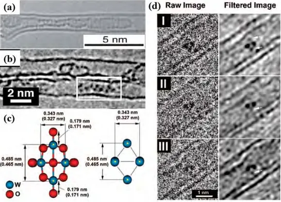
Fig. 1.9 - Examples of CNTs filled with halides via a one-step molten phase method (without prior opening). (a) A DWCNT filled with crystalline CsI (diameter of the inner tube, 3.9 nm; diameter of the outer tube, 4.7 nm). The inset image shows the rocksalt structure of the encapsulated CsI. Scale bar is 2 nm [26]; (b) and (c) HRTEM image of a triple-walled carbon nanotube filled with a helically twisting 2 × 1 × ∞ HgI2 crystal and the simulated structure model
of the crystal [24]; (d) to (i) a 1D BaI2 chain encapsulated in a SWCNT: (d) and (e) HRTEM images, (f) side-on and
end-on views of the atom positions derived from the lattice image, (g) Scherzer focus simulation of derived composite, (h) side-on and end-on views of the composite, (i) coordination model derived for a 1D BaI2 chain [113].
1.2.4 Species Encapsulated within CNTs
In principle, every type of material including atoms, molecules and phases can be inserted into the CNT cavity and experimentally, successful insertions of atoms, molecules, elements, and compounds have been achieved up to now. In this manuscript, representative papers in which direct proof of filling such as TEM imaging are provided will be introduced, while other related references in which the fillings are merely confirmed by spectroscopic investigations will not be mentioned here.
20
1.2.4.1 Atoms (Isolated, or as Chains)
When atoms are introduced into nanotubes, it is nearly impossible for them to remain isolated due to their relative instability. Meanwhile, demonstrating the presence of isolated atoms in SWCNTs or DWCNTs is experimentally challenging. Hence, the encapsulated atoms tend to form elongated crystals as nanowires (see next) or single atom wide chains, although only a few examples related to the latter can be found in the literature. The first example was iodine, which was observed to adopt a double-helix structure [34]. In the following works involving iodine filling [36, 114], besides double chain, single and triple iodine chains were demonstrated as well (Figs. 1.10 a and b).
Fig. 1.10 - First column (a), from top to bottom: the first example of SWCNTs filled with a double-helix chain of iodine atoms, as evidenced by means of high-resolution Z contrast TEM, then HRTEM image of a SWCNT filled with a single iodine chain, then HRTEM image of a SWCNT filled with a triple-helix iodine chain. The corresponding structure models (side view) are provided for each case below the related images. Scale bar is ~1.5 nm [34, 41]; Second column (b): HRTEM images of sulfur chains with linear (first and third images) or zigzag (second image) conformation inside a SWCNT or a DWCNTs, scale bar is ~2 nm [42]; (c) HRTEM image of a DWCNT filled with a double-helix Se chain displaying a pitch length of ~ 2 nm [43].
One thing to point out is that iodine crystal is observed – instead of single-atom chain -when the host SWCNT has a large diameter as shown in [36, 114], yet such a configuration is very rare. Interestingly, when attempt to dope the C60@SWCNTs with iodine was made, a bent I2 chain
intercalated into the fullerenes inside a SWCNT was observed in addition to the embedded iodine atoms among two adjacent fullerene molecules [115]. The formation of these structures could be
21
attributed to the obstruction of fullerenes on the filling pathway and the bonding of the inserted atoms, which also resulted in the observation of isolated Cs atoms and K atoms in peapods [116, 117]. A chain structure was also proposed for the encapsulated Cs within SWCNTs prepared by Jeong et al. [36], inspired by the pioneering work of iodine filling [34]. Recently, a Japanese group reported the synthesis of linear sulfur chains [42] and double helices of selenium [43] inside CNTs (Fig. 1.10 b and c), both of which were totally different from the atomic arrangement in bulk elements. These progresses may indicate the potential development of a new branch of chemistry for the above elements.
1.2.4.2 Molecules (Isolated, or as Chains)
When molecules are intended to be inserted into nanotubes, the cavity size of the host nanotubes should be taken into account if the diameter of guest molecule is large (e.g. more than 2 nm) which may not be accommodated by a SWCNT or DWCNT. So far, filling nanotubes with molecules principally involves SWCNTs except for some scarce examples concerning the loading of drugs into MWCNTs. The first molecules ever introduced into SWCNTs were fullerenes, thereby forming the so-called nanopeapods as mentioned above. Later on, many fullerene derivative fillings have been performed including higher fullerenes (C70 [118], C78 and C90 [119]), fullerene epoxide
(C60O [120]), endohedral fullerenes (Gd@C82 and Dy@C82 [119], N@C60 [121], Sc3N@C80 and
ErxSc3-xN@C80 [122], Dy3N@C80 [123], La@C82 and La2@C82 [124], Sm@C82 [125], Sc2@C84
[126], Gd2@C92 [127], Ce@C82 [128], D5d-C80 and Ih-Er3N@C80 [129], Sc3C2@C80 [130]),
fullerenes functionalized with ester C61(COOH)2 or carboxylic groups C61(COOEt)2 [131],
heterofullerenes (C59N azafullerene [132]), as well as 13C isotope enriched fullerene peapods [133].
Besides the linear fullerene chain, a ‘silo’ configuration can also form when fullerenes are encapsulated inside large diameter nanotubes [92].
Although CNT is considered as a 1D material, the synthesis of linear carbon chains (also called carbyne) only one atom wide and the presence of sphybridization has always been another goal for scientists to achieve [134]. It has been accomplished by initially filling CNTs with polyyne [135] or adamantane [136] molecules and then subsequently annealing the filled nanotubes in vacuum to promote the fusion of the encapsulated molecules, somehow in a similar fashion to the coalescence
22
behavior of peapods (see section 1.2.6). The carbyne is theoretically predicted to possess higher strength, elastic modulus and stiffness than other members in the carbon family including diamond, carbon nanotubes and graphene, which will motivate more efforts on its synthesis at bulk scale.
Apart from fullerenoids as the most popular filling molecules, other organic molecules have also been successfully inserted into nanotubes (Fig. 1.11 a and b), such as metallocenes [122, 137-143], octasiloxane [120], ortho-carborane and related molecules [144, 145], fulvalenes [146], Zn-diphenylporphyrin [118, 147], Pt-porphyrin, rhodamin-6G, and chlorophyll [147], β-carotene [101], squarylium (SQ) dye [99], and α–sexithiophene [148].
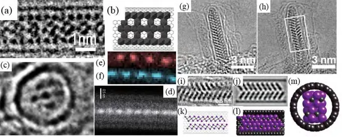
A peculiar example with regard to the insertion of discrete molecular anion into DWCNTs was reported by Sloan et al. [149]. The inserted [W6O19]2- "Lindqvist ion" which belongs to the family
of inorganic polyoxometalate (POM) ions exhibits a nonspheroidal shape and thus can lock into position within sterically matched nanotube capillaries. Owing to these advantages, the constituent W6 cation framework in the ion can be directly imaged by means of HRTEM (Fig. 1.11 c and d).
Fig. 1.11 - (a) HRTEM image of a SWCNT filled with α–sexithiophene molecule by gas phase method, two parallel
chains formed by the molecules are shown [148]; (b) HRTEM image of a short chain of ortho-carborane molecules formed within a ~ 1.6 nm diameter SWCNT [150]; (c) shows structure models of the [W6O19]2- anion with oxygen
included (left) and excluded (right);(d) a sequence of HRTEM images (left) obtained from a single [W6O19]2- anion
23
Furthermore, a possible electronic interaction between the nanotube and the encapsulated anion can be verified on the condition that expansion between the two atom columns each containing just a pair of W atoms was observed.
1.2.4.3 Pure Elements (as Nanowires or Nanoparticles)
Except for the formation of chains when elements such as iodine, sulfur, or selenium are inserted into SWCNTs or DWCNTs, nanocrystals are obtained when other elements (mostly when metals are involved) are encapsulated within SWCNTs or DWCNTs. For instance, the synthesis of confined Ru nanowires [19], Bi nanowires [80], Ag nanowires [19, 97, 98, 151, 152], Au nanowires [98], Pt nanowires [98], Pd nanowires [98], La nanowires [153], Eu nanowires [154, 155], Co nanoparticles [156], Fe nanoparticles/nanowires [137, 157, 158], Ni nanocluster [159, 160] have been reported in the literature (Fig. 1.12).
Among these, only Bi and Eu nanowires are directly prepared by filling SWCNTs with pure metals, others are prepared via in situ transformations on the hybrid nanotubes filled with intermediate compounds (e.g. salts). Nanowires of transition metals (e.g. Co, Fe, Ni) may exhibit remarkable magnetic properties while they are barely produced yet, thus more explorations are required. It should be pointed out that in [157, 158], no clear evidence demonstrating the presence
Fig. 1.12 - HRTEM images of (a) Ni clusters filled SWCNTs obtained by annealing initial NiCp2-filled
SWCNTs at 500 °C for 2 hours [159]; (b) SWCNTs filled with Eu nanowires (left) and magnified image (right). In the magnified image, red lines correspond to the side wall of the SWCNT, and purple circles correspond to the Eu atoms [154]; (c) a Co-nanoparticle-filled SWCNT [156].
24
of iron nanowires was given, at least from the TEM and HAADF images. However, lanthanum nanowires with typical length of ~10 nm are claimed to be obtained by heating the La2@C80
peapods to trigger the coalescence of metallofullerene molecules. This may give some hints for generating other one-dimensional metallic wires.
1.2.4.4 Compounds (as Chains, Nanowires, or Nanoparticles)
When the desired filling elements possess high melting points and/or high surface tension at the molten state, filling SWCNTs or DWCNTs with compounds can be taken as an efficient alternative. Additionally, filling compounds in solutions may also be the option when a low-temperature filling process is needed or when the elements considered are poorly soluble. The favorite compounds for filling SWCNTs (or DWCNTs) are halides because of their versatility (including fluorides, chlorides, bromides, and iodides), moderate melting points (usually less than 1000 °C), good solubility in many usual solvents (chloroform, water, etc.) and the distinctive ability (compared with other desired filling compounds) to open the nanotube and then fill the nanotube simultaneously. Up to now, halides of a wide range of elements (alkali metals [24, 26, 27], alkaline earth metals [25, 99], transition metals [24, 25, 98, 113, 157, 158, 161-163], lanthanides [22, 113], post-transition metals [164, 165] and their mixtures [21, 25, 29]) have been successfully inserted into SWCNTs (or DWCNTs) mainly by the Oxford Group (see Fig. 1.9), which is one of the most active groups involved principally in filling SWCNTs with inorganic compounds since 1998 [19], as well as other groups around the world.
Fig. 1.13 - (a) HRTEM image of SWCNTs filled with PbO. White arrows point to nanotubes filled with lead oxide, a high filling rate≥70% was reported [108]; (b) HRTEM image and detail of UO2 clusters
inside SWCNTs [33]; (c)-(e) TEM image and detail of CsOH crystals inside SWCNTs (scale bar = 1.0 nm), and corresponding Scherzer defocus simulated TEM image [33].
25
Besides halides, filling SWCNTs (or DWCNTs) with nitrates such as AgNO3 [151, 152, 166],
Bi(NO3)3 [80], UO2(NO3)2 [33], oxides including CrO3 [30], Sb2O3 [31, 32], PbO [108], RexOy [91],
UO2 [33], hydroxides (KOH and CsOH [33]), HgTe [167], MnTe2[168], GeTe [169] have also been
reported in the literature (Fig. 1.13).
1.2.5 Filling Mechanisms
Although many filling examples have been reported so far, the filling mechanisms are not clearly understood yet, especially in respect to filling via liquid phase method which is frequently used in this manuscript. It is initially assumed that the nanocapillary wetting for filling of nanotubes can also be described by the equation of Young and Laplace, as shown below:
∆P γ (1.2)
where ∆ refers to the pressure difference, refers to the surface tension, and refer to the two radii of curvature for a curved surface. When the phenomenon of capillary rise occurs in a nanotube, the liquid wets the wall of the nanotube and a meniscus will be formed at the end of the capillary rise, as illustrated in Fig. 1.14.
Fig. 1.14 - Illustration of a capillary rise
If the meniscus is taken to be spherical in shape and the liquid meets the circularly cylindrical capillary wall at some angle , Eq. 1.2 then becomes
26
where r refers to the radius of the capillary. Meanwhile, the pressure difference also equals the hydrostatic pressure drop in the column of liquid in the capillary. Thus ∆P ∆ρgh, where ∆ denotes the difference in density between the liquid and gas phase, g is the acceleration due to gravity and h denotes the height of the meniscus above the liquid surface. Eq. 1.3 may write
h
∆ (1.4)
…which is also known as the Jurin's law since the XVIIIth Century. It can be seen that if (also called as contact angle) is larger than 90° will be negative, which indicates that an external pressure is required to drive the capillary. Hence, only if the contact angle is below 90° can a spontaneous capillarity action occur (however, a recent study demonstrates the possibility of capillary adsorption of metal nanodroplets with θ>90° by SWCNTs stemming from the calculation). On the other hand, the contact angle can be derived from Eq. 1.5:
cosθ (1.5)
where and refer to the tensions at the solid-vapor and solid-liquid interfaces, respectively. However, relevant data on the two tensions are not easy to obtain thus making the calculation of contact angle difficult.
In the early days, Dujardin et al. [12] investigated the wetting and capillarity of MWCNTs regarding various elements. Their results implied that only materials with low surface tension at melting point could wet the nanotubes then be drawn inside the nanotubes and a cut-off point for surface tension was between 100~200 mN/m. The latter could then provide an upper limit to the effect of Jurin's law (see eq. 1.4 above) which indicates in principle that the filled length h increases as surface tension increases. Likewise, if we go back to Eq. 1.4, it is found that h is inversely proportional to r, thereby, for a given liquid, a longer capillary rise should be observed for narrow tubes than for large tubes, meaning higher filling efficiency. However, this is not in accordance with the conclusions from early works dealing with filling with liquids, while comparing MWCNTs with a narrow and wide inner cavity, respectively. Ugarte et al. [170] claimed that only nanotubes with inner diameter ≥4 nm were filled while nanotubes with inner diameter of ~1-2 nm were not filled when filling MWCNTs with molten silver nitrate was carried out. Furthermore, following the discovery of SWCNTs several early attempts to fill SWCNTs with molten materials did not succeed [171]. Hence, it is suggested that the equation of Young and Laplace established for sub-millimeter
27
capillaries may not be valid for the sub-nanometer capillaries (‘nanocapillarity’). Until 1999, higher filling yield was observed for regular SWCNTs (inner diameter ~1.4 nm on average) than for MWCNTs when molten materials were used for filling. Likewise, narrow nanotubes were found to be firstly filled during the filling process of Se vapor [89] and the filling efficiency of Bi via the gas and liquid routes was found to be higher for SWCNTs than for MWCNTs [80]. Overall, very high filling rates were achieved when materials involving PbI2 [164], KI [25] and PbO [108] were
inserted into SWCNTs and the existence of nanocapillarity can thus be confirmed.
Despite the success in filling SWCNTs, factors involved in the filling process and how they affect the final filling efficiency are not clearly defined. Since the capillarity of nanotubes is directly related to the surface energies of interaction between the liquid and the solid surface of nanotubes, wetting issue should be taken into consideration firstly. Nevertheless, there are high chances that discrepancies between nanowetting and regular macrowetting may occur. For instance, though surface tension of the filling material is suggested as a determining factor for successful filling by Dujardin et al. [12], several studies reported that the introduction of molten material with high surface tension results in higher filling efficiency compared with the introduction of material with low surface tension [25]. In addition, it was recently proposed [6] that viscosity which is considered to only affect the wetting dynamics in macrowetting is likely to play an important role in nanowetting, while the effect of gravity which is considered in macrowetting will not be taken into account in nanowetting because the related weights of the tiny amount of liquid involved is negligible with respect to capillary forces. The proposed factor, viscosity, which may influence the nanowetting, is deduced from the fact that whatever the tube diameter, friction forces increasingly oppose the wetting forces because the tube/liquid contact surface where the friction forces take place increases as the liquid proceeds in the tube, while the gas/liquid/solid contact line where the capillary forces take place remain constant. Finally the cease of the liquid progression is induced once the capillary forces equilibrate the friction forces.
It is likely that viscosity and/or nanowetting are not the only criteria to consider for controlling the filling of nanotubes. The configuration of the filling materials when entering into the cavity of nanotubes should be understood, as a complex may form for certain molten salts or solvated molecules which may not be accommodated by nanotubes with inner diameter below ~1nm due to their large size. Moreover, the intrinsic saturating vapour pressure value of the guest materials is
28
suggested to be important when the molten phase method is used [172]. Though the filling temperature is maintained below the boiling point of the filling material, partial vapour pressure actually develops in the sealed vessel which is likely to push the molten material into the cavity of nanotubes. In this sense, materials with high saturating vapour pressure should provide high filling efficiency (assuming that other parameters are equal). Such an aspect has not been investigated yet. Aside from above, local conditions may play an important role as well, as probably the only reason why, within the same filling experiments, some nanotubes are found extensively filled, whereas adjacent ones with open ends are found empty (frequently observed in our work).
1.2.6 Behaviors, Properties and Applications
As stated above, a large variety of filling experiments has been performed during the short period of development of filling CNTs, especially regarding to filling SWCNTs, while experimental proofs indicating the peculiar properties of X@SWCNTs are relatively rare. Meanwhile, most theoretical work has been focused on the anticipated possibility to tune the SWCNT band gap owing to the inserted material, or to modulate the band gap of the inserted material owing to the enforced structural deformations, while few efforts have been devoted to theoretically predict the electronic properties of filled CNTs (except peapods). So far, simulations of the formation of KI crystals [173], spontaneous filling process of DNA [56], encapsulation of acetylene molecules and their polymerization within SWCNTs [174], modeling of SWCNTs filled water [54], simulations of structural transition of Cu nanowires [175] and electrical transport property of Ge nanowires [62] encapsulated in SWCNTs, quantum chemical simulation of the electronic properties and chemical bonding of the hybrid (Sc, Ti, V)8C12@(12, 0)SWCNTs [174], calculations on the modified
electronic properties of SWCNTs inserted by Ag or CrO3 [176], and many predictions concerning
the magnetic properties of transition metal filled SWCNTs, specifically Fe [57, 59-61, 177], have been carried out. With more and more attention attracted to this research field, we can expect discoveries of new properties of filled SWCNTs and progress of theories on these hybrid SWCNTs in the future.
29
1.2.6.1 Peculiar in-Tube Behavior (diffusion, coalescence, crystallization)
Thanks to the unidirectional confinement given by the inner cavity of carbon nanotubes, especially SWCNTs and DWCNTs, many peculiar in-tube behaviours of the filling material are induced either spontaneously upon filling or by imposing an external stress after filling (annealing, irradiation). As one of the first two synthesized X@SWCNTs, the intriguing behaviours of peapods have been extensively investigated. In the first report on peapods [20], it was found that the encapsulated fullerene molecules coalesce into smaller tubular structures with a capped end when exposed to a 100 kV electron beam in a TEM (Fig.1.15).
Fig. 1.15 - Sequence of HRTEM images (100 kV, ~300 seconds between images) illustrating the progressive coalescence of a chain of C60 moleculeswithin a 1.4
nm diameter SWCNT under the irradiation. (a) starting situation, showing a well periodic display of the fullerenes; (b) pairs of C60 are seen indicating the
initiation of dimerization; (c)coalescence starts, yet not uniformly; (c) coalescence proceeds and longer capsules are formed. Scale bar 2 nm [178].
Subsequently, more electron beam-induced behaviors were discovered. In a partially filled SWCNTs, diffusion of the fullerene molecules were observed inside the cavity [45] (Fig.1.16), while in a SWCNT filled with densely packed fullerenes two adjacent molecules tended to dimerize [45, 178], as illustrated in Figs. 1.15. Further, with prolonged irradiation, the dimers coalesced into higher, elongated fullerenes and ultimately ‘two-wall, coaxial tubes’ (CAT) were obtained [45, 178], which were close to double-walled carbon nanotubes (DWCNTs), whose structure had been described prior to the discovery of peapods [179]. The irradiation-induced coalescence is understood as the overcome of activation barrier thanks to the energy brought by the electron beam.
![Fig. 1.3 - TEM images of three types of CNTs, from left to right are SWCNTs, DWCNTs and concentric-type MWCNTs, respectively [4, 9, 10]](https://thumb-eu.123doks.com/thumbv2/123doknet/2153095.9298/13.892.208.698.750.1051/images-types-cnts-swcnts-dwcnts-concentric-mwcnts-respectively.webp)
![Fig. 1.7 - TEM images of MWCNTs filled with (a) polystyrene nanobeads via bringing MWCNTs into contact with the related suspension in ethylene glycol and deionized water [94]; (b) Fe 3 O 4 nanoparticles via bringing MWCNTs into](https://thumb-eu.123doks.com/thumbv2/123doknet/2153095.9298/24.892.149.785.97.324/polystyrene-nanobeads-bringing-suspension-ethylene-deionized-nanoparticles-bringing.webp)