O
pen
A
rchive
T
oulouse
A
rchive
O
uverte (
OATAO
)
OATAO is an open access repository that collects the work of Toulouse researchers
and makes it freely available over the web where possible.
This is an author -deposited version published in:
http://oatao.univ-toulouse.fr/
Eprints ID: 3993
To link to this article: DOI:10.1016/j.proeng.2010.03.110
URL:
http://dx.doi.org/10.1016/j.proeng.2010.03.110
To cite this version:
SHAHZAD Majid, CHAUSSUMIER Michel, CHIERAGATTI Rémy, MABRUCatherine, REZAI-ARIA Farhad. Influence of anodizing process on fatigue life of a machined
aluminium alloy. Procedia Engineering, 2010, vol. 2, n° 1, pp. 1015-1024.
ISSN 1877-7058
Any correspondence concerning this service should be sent to the repository administrator:
Available online at www.sciencedirect.com Procedia Engineering 00 (2009) 000–000
Procedia
Engineering
www.elsevier.com/locate/procediaFatigue 2010
Influence of Anodizing Process on Fatigue Life of Machined
Aluminium Alloy
M. Shahzad * - M. Chaussumier - R. Chieragatti -C. Mabru - F. Rezai-Aria
Université de Toulouse, Institut Clément Ader, ISAE DMSM, 10 Av. Edouard Belin, 31055 Toulouse Cedex 4, France
Received 26 February 2010; revised 10 March 2010; accepted 15 March 2010
Abstract
In order to investigate the coupled effects of machining and anodizing processes on fatigue life of alloy 7010-T7451, a series of rotating bending fatigue tests were conducted at 60Hz. In the as machined condition, test results showed that fatigue life is surface roughness dependent and that fatigue life decreases with an increase in surface roughness and this effect is found to be more pronounced in high cycle fatigue where major portion of fatigue life is consumed in nucleating the cracks. Effects of pre-treatments, like degreasing and pickling employed prior to anodizing, on fatigue life of the given alloy were also studied. Results demonstrated that degreasing showed no change in fatigue life while pickling had negative impact on fatigue life of specimens. The small decrease in fatigue life of anodized specimens as compare to pickled specimens is attributed to brittle and micro-cracking of the coating. Scanning electron microscopic (SEM) examination revealed multi-site crack initiation for the pickled and anodized specimens. SEM examination showed that pickling solution attacked the grain boundaries and intermetallic inclusions present on the surface resulting in pits formation. These pits are of primary concern with respect to accelerated fatigue crack nucleation and subsequent anodized coating formation.
Keywords: 7010-T7451; Fatigue; Pickling; Pits; Anodization
1. Introduction
It is well-established that fatigue life of a machined component depends strongly on its surface condition and in most cases fatigue failure begins at the surface. This is due to the fact that surface is exposed to severe environmental conditions and bear the greatest loads. Since fatigue cracks nucleate at the surface, therefore surface topography generated by machining plays an important role in determining the fatigue life [1-2]. Surface roughness is supposed to introduce stress concentrators that encourage the crack nucleation and accelerates the early fatigue crack growth [3], hence reducing fatigue life compared to perfectly smooth specimens. Being subjected to different environmental conditions, aluminium alloys often undergo different surface treatments against wear and corrosion phenomenon. Anodizing is well-known electrolytic process that produces controlled columnar growth of amorphous
* Corresponding author. Tel.: +33 561 339 148; fax: +33 561 338 595 E-mail address: majid.shahzad@isae.fr.
c 2010 Published by Elsevier Ltd. Procedia Engineering 2 (2010) 1015–1024 www.elsevier.com/locate/procedia 1877-7058 c 2010 Published by Elsevier Ltd. doi:10.1016/j.proeng.2010.03.110
aluminium oxide on the surface of aluminium alloys [4]. In spite of the benefits obtained by anodizing in terms of corrosion resistance, it is proved that anodizing has adverse effect on fatigue life of aluminium alloys [5-7]. It is generally accepted that this reduction in fatigue life is directly attributed to the brittle and porous nature of oxide layer and tensile residual stress induced during anodizing process [8-9]. Also, localized corrosion, in the form of pits, occurring during the pre-treatment solution exposure and these pits has been identified as cause for accelerated crack nucleation during subsequent fatigue loading [10-11]. Barter et al (12) have observed the influence of microstructure and different surface treatments on the growth of small cracks in a typical high strength aluminium alloy 7050-T7451. They reported that pickling can lead to pitting of grain boundaries with significant fatigue life implication. Abramovici [13] showed that changing the pickling time had a great influence on fatigue life for 7000 series. Since in the presence of these surface defects, fatigue failure of a component can be greatly accelerated, an inclusive understanding of these pre-treatment corrosion mechanisms is therefore of scientific interest.
The aim of this study is surface characterization and to demonstrate the coupled effects of surface roughness and pre-treatments, degreasing and pickling, along with anodization on fatigue life of alloy 7010. Two different machining conditions were employed to obtain two different initial surface roughnesses. Degreasing, pickling and anodizing were then performed. Scanning electron microscope equipped with energy dispersive spectroscopy (EDS) was used to analyze the fractured surfaces and to identify crack origin sites for specimens with different surface treatments.
2. Experimental details
2.1. Material
The material investigated in this work is 7010-T7451 aluminium alloy and is provided in the rolled plate form of 70mm thickness. The chemical composition is (in wt%): 6.45 Zn; 2.86 Mg; 1.98 Cu; 0.20 Mn; 0.25 Zr; 0.22 Fe; 0.12 Si; 0.15 Cr and 0.12 Ti. Mechanical properties of this alloy are; yield strength 464 and 458 MPa, ultimate tensile strength 526 and 525 MPa and elongation 9.8% and 8.4% in the longitudinal (L) and transverse (T) directions to the rolling plane directions respectively.
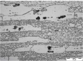
Using standard metallography procedures, metallographic sections were examined using optical microscopy technique in the as polished condition. Study of the microstructure revealed that it is composed of unrecrystallized and recrystallized grains and latter are highly elongated in the rolling direction as shown in figure 1. Mainly two types of constituent particles (inclusions) were found in this material: Mg2Si, Al7Cu2Fe and these were generally
located in recrystallized grains.
M. Shahzad et al. / Procedia Engineering 00 (2010) 000–000 3
2.2. Specimen Preparation
Cylindrical test specimens, as shown in figure 2, were machined by turning without using lubricant. Turning was performed on 2 axes numerical lathe RTN20 of mark RAMO. Fatigue specimens were prepared in such a way that maximum load is applied perpendicular to the rolling direction.
Figure 2: Rotary bending fatigue specimen (dimensions in mm)
To characterize the roughness of a machined surface, various geometric parameters such as average roughness (Ra), peak to valley height roughness (Ry) and 10-points roughness (Rz) are generally used. These parameters are calculated from profile height (z) distribution over an assessment length Ɛ. In this study Ra has been used as principal parameter to define surface roughness given as,
³
az
x
dx
l
R
0)
(
1
lTwo types of machined surfaces (Ra=0.6μm and Ra=3.2μm) were produced. To illustrate the different surface treatment effects on fatigue life, specimens were categorized in 4 groups as shown in table 1. The first group, involving only machined specimens, with no surface treatments was used to build reference fatigue curve for comparison purpose with other three groups.
Table 1: Classification of specimens according to surface treatment
Degreasing Pickling Anodizing
Group 1 No No No
Group 2 Yes No No
Group 3 Yes Yes No
Group 4 Yes Yes Yes
2.3. Surface Treatments
To enhance the corrosion resistance of aluminium alloys, anodizing is one of the surface treatments exercised in industry. It is accomplished by making the work-piece anode while suspended in a suitable electrolytic cell at suitable temperature and voltage [4]. Before anodizing process, an appropriate pretreatment of surface is necessary which consist of degreasing and pickling and purpose of these pre-treatments is to produce a chemically clean surface. For degreasing, the specimens are immersed in a special detergent that removes oils, grease and solid dust particles from metal surface. Pickling is employed to remove the natural oxides and other compounds from surface by means of a solution which acts chemically upon the compounds. Removal of oxide layer allows for a more conductive surface thus facilitating electrochemical processes such as anodizing.
Figure 3: S-N fatigue test results for two different surface roughnesses
Specimens degreasing was carried out in aqueous solution of sodium tri polyphosphate Na2P3O4 and Borax
Na2B4O7 at 60°C for 10-30 minutes followed by demineralised water rinsing. Pickling was done in aqueous
solution of H2SO4 acid and anhydride chrome CrO3 at 60°C between 1-10 minutes followed by rinsing. Chromic
acid anodization was accomplished in anhydride chrome CrO3 solution at 45°C under 50 volts for 55 minutes. The
average thickness of oxide layer produced by the process was measured to be about 3μm.
2.4. Fatigue Testing
Rotating bending fatigue tests were performed at frequency of 60Hz in laboratory conditions to obtain the S-N curves. The choice of this type of testing was made because it produces the greatest amount of stress on the specimen surface.
3. Results and discussion
3.1. Fatigue test results
The results of S-N curves obtained for all four groups are shown in figs. 3-5. Figure 3 correspond to group 1 specimens in as machined condition and without any subsequent surface treatment. Figures 4-5 correspond to S-N curves of specimens which undergone different surface treatments after machining. From this it is possible to evaluate the influence that each treatment has on fatigue life. The results of rotating bending fatigue tests for first group is shown in figure 3. Surface roughness is clearly effective in reducing fatigue life for this material. For high stress region there is about 10% decrease in fatigue strength while in low stress regime there is 32% decrease. This confirms that surface roughness plays a vital role especially in high cycle fatigue [14] in which major part of fatigue life is consumed in nucleating the cracks.
50 75 100 125 150 175 200 225
1,00E+04 1,00E+05 1,00E+06 1,00E+07
Number of Cycles to failure
M ax. St ress ( M Pa) Ra =0.6 µm Ra =3.2 µm
M. Shahzad et al. / Procedia Engineering 00 (2010) 000–000 5
S-N fatigue curves for the specimens with low and high roughness after surface treatments i.e. degreasing, pickling and anodizing are shown in figure 4 (a) and (b) respectively. The degreasing showed no remarkable influence on fatigue life, for both surface conditions, while pickling was found damaging in reducing fatigue life considerably. This decrease in fatigue life caused by pickling could be associated with degradation of surface condition as compare to machined surface of the specimen. The presence of pits on the specimen surface plays a vital role in accelerating the fatigue crack nucleation and their subsequent growth.
50 75 100 125 150 175 200 225
1.00E+04 1.00E+05 1.00E+06 1.00E+07
Number of Cycles to failure
Max. S tress (MP a) Reference degreased pickled anodized
Figure 4 (a): S-N curves for lower roughness specimens (Ra = 0.6μm without any treatment is taken as reference)
50 75 100 125 150 175 200 225
1.00E+04 1.00E+05 1.00E+06 1.00E+07
Number of Cycles to failure
Max. S tress ( M P a ) Reference Degreased Pickled Anodized
Figure 4(b): S-N curves for higher roughness specimens (Ra = 3.2μm without any treatment is taken as reference)
From graphs it is also clear that anodization decreased the fatigue life slightly as compare to pickled specimens for this alloy. This decrease could be attributed to the brittle nature of the oxide coating, which readily crack when loaded, and due to the presence of micro-cracks in the coating, which may result in an early fatigue crack initiation. Since oxide layer adheres extremely well to substrate, any crack that develops in it acts like stress raiser and propagates to substrate. Another important aspect is that pickling effect is more prominent for low roughness specimens than higher roughness specimens especially in high cycle fatigue as can be seen in figure 5. Analysis of these S-N curves using Basquin’s model allows in defining the loss of fatigue life. For the lower roughness specimens, loss is 32.6% for 106 cycles as it is only of 12.4% for 105 cycles. For higher roughness specimens, loss is
only of 18.7% at 106 cycles and 7.7% for 105 cycles. Through these results, it appears that the effect of pickling is
50% more important in case of initial lower roughness.
50 75 100 125 150 175 200 225
1.00E+04 1.00E+05 1.00E+06 1.00E+07
Number of Cycles to failure
Ma x . St re s s ( M Pa ) Ra=0.6 Ra=3.2 Ra=0.6 pickled Ra=3.2 pickled
Figure 5: SN curves for machined and pickled specimens
3.2. SEM analysis
Scanning electron microscopic examination was carried out after each treatment to analyze its effects prior to fatigue testing. Also fractured surfaces of the specimens with different treatments were examined by SEM to identify the crack origin sites. In addition, EDS was used for intermetallic particles identification for those found to nucleate the cracks. For the specimens in as machined condition, fatigue cracks had been observed to nucleate at inclusions Mg2Si and Al7Cu2Fe present at the surface. In some cases, inclusions are not exactly at surface but are
very close to it, usually at 10μm at its closest point. Patton [15] studied the same alloy and also showed that most of cracks initiated by the fracture of particles present in the alloy. Pickling process was found to attack the grain boundaries and inclusions resulting in pits formation on the surface as shown in figure 6 (a) and (b), which in turn acted as stress concentration facilitating crack initiation and also promoting crack growth. The pickling pits which were found to nucleate fatigue cracks were about 8-12μm deep. In some cases, where two pits were close to each other, cracks nucleation grew together to form single crack front. Presence of the many pits on the surface also explains multi-crack initiation sites for the specimens which were treated with pickling solution as shown in figure 7 as compared to machined specimens. This phenomenon of multiple crack nucleation was observed for both initial surface roughnesses i.e. Ra = 0.6μm and Ra = 3.2μm for group 3 specimens.
M. Shahzad et al. / Procedia Engineering 00 (2010) 000–000 7
Figure 6: (a) Pickling process resulting in the pit formation (b) Fatigue crack initiated from one of pit at specimen surface
ion sites for specimen undergone pickling sqjdgsqhsqhsqh in as machined condition
Pickling Pit
Fatigue
Figure 7: (a) Single crack nucleation site for specimen (b) Multi-crack nucleat
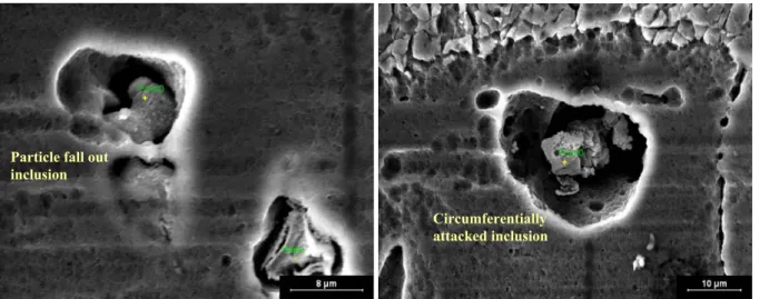
It was revealed by SEM observation that some inclusions were attacked on their periphery and some were dissolved to various extents leaving a trace behind as shown in figure 8. This phenomenon is also reported by Birbilis [16]; he showed that inclusion type had an influence on pitting process and classified pit morphologies into two categories for aluminium alloys. One type is designated as circumferential that appears a ring of attack around an inclusion and other type is referred to as selective dissolution. Pits structures for latter type are typically deeper and may have remnants of particle in them. This type of damage has also been referred to as particle fall out. EDS M. Shahzad et al. / Procedia Engineering 2 (2010) 1015–1024 1021
analyses were conducted on these pits, figure 8 (c), to identify the type of inclusions attacked by the pickling
(a) Particle fall out and circumf issolved inclusion
solution and found that mainly it was Al7Cu2Fe.
Particle fall out inclusion
Circumferentially attacked inclusion
erentially attacked inclusion (b) Circumferentially d
Figure 8: (c) EDS spectra for Al7Cu2Fe
For anodized specimens, multiple crack nucleation sites were also found on the fractured surface as can be seen in figure 9 (a). Shiozawa et al. [17] also reported this phenomenon that number of crack initiation sites increased for the anodized specimens compared to untreated ones.
M. Shahzad et al. / Procedia Engineering 00 (2010) 000–000 9
When analyzed thoroughly by SEM, it was found that some of the fatigue cracks for anodized specimens were strate. For relatively small pits, it was discovered that anodic coating was actually able to grow
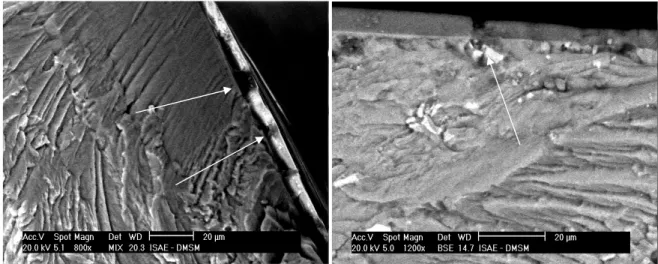
ngth [9]. Also the presence of irregularities (figure 10b) in the coating is important consideration affecting crack nucleation and
ularitie the crack nucleation
as well as on the delamination. The presence of these irregularities in the coating can be correlated to the presence of
Figure 10: (a) Partial delamination of coating from substrate (b) Irregularities found in the coating
initiated by pickling pits beneath the coating as shown in figure 9 (b) while others were started from coating and the propagated to sub
over these pits and produce relatively a smoother surface.
Pickling pits beneath
anodized coating
Figure 9: (a) Specimen with anodized coating with multi-site crack nuclea
Although anodized coating was found to be quite un examination showed that in some region there was partial
tion (b) fatigue crack started from pits beneath the anodized coating
iform in most regions around the specimen, SEM delamination; figure 10a indicated by arrows, at the interface of coating and substrate and this delamination is related to the interfacial shear stre
propagation. Local stress concentration due to the irreg s may have provocative effect on pickling pits and inclusions.
at degreasing had no effect while pickling was ss rface of specimen by attacking the grain boundaries and intermetallic inclusions
s rface. Also by comparing the fatigue decrease for pickled
is
a Unit Ltd, London, 1994.
7. Lonyuk B., Apachitei I. and Duszczyk J., The effect of oxide coatings on fatigue properties of 7475-T6 aluminium alloy, Surface and Coatings Technology, 2007; 21: 8688-8694.
8. Camargo A. and Voorwald H., Influence of anodization of fatigue strength of 7050-T7451 aluminium alloy, Fatigue and Fracture of Engineering Materials and Structures, 2007; 30: 993-1007.
9. Cirik E. and Genel K., Effect of anodic oxidation on the fatigue performance of 7075-T6 alloy, Surface and Coatings Technology, 2008; 202, 5190-5201.
10. Dolley E.J. and Wei R.P., The effect of pitting corrosion on fatigue life, Fatigue and Fracture of Engineering Materials and Structures, 2000; 23 , 555-560.
11. Pao P.S., Gill S.J. and Feng C.R., On fatigue crack initiation from corrosion pits in 7075-T7351 aluminium alloy, Scripta Materialia, 1998; 43(5), 391-396.
12. Barter S.A, Sharp P.K and Clark G., Initiation and early growth of fatigue cracks in an aerospace aluminium alloy, Fatigue and Fracture of Engineering Materials and Structures, 2002; 25, 111-125.
13. Abramovici E., Leblanc P. and Weaver B., The influence of etch pits on fatigue life of anodized aluminium alloys, Conference proceedings of International Conf. and Exhibits on Failure Analysis, 1991, 21-32.
14. Suraratchai M., Influence de l’etat de surface sur la tenue en fatigue de l’alliage d’aluminium 7010, PhD thesis, Université Toulouse III; France: 2006.
15. Patton G., Rinaldi C. And Fougeres R., Study of fatigue damage in 7010 aluminum alloy, Materials Science and Engineering A, 1998, 207-218.
16. Biribilis N., Buchheit R.G., Electrochemical characteristics of intermetallic phases in aluminium alloys, Journal of Electrochemical Society, 2005; 152: B140-B151.
17. Shiozawa K., Kbayashi H., Terada M. and Matsui A., Effect of anodized coatings on fatigue strength in aluminium alloy, 5th International Conference of Computational and Experimental Methods, 2001; 6: 397-406.
4. Conclusions
The present study focused on the influence of anodizing pretreatment solutions on the fatigue life of machined th
aluminium alloy. Results obtained from fatigue testing showed
proved to be detrimental in reducing the fatigue life significantly. SEM observation showed that pickling proce caused formation of pits on the su
present in this alloy. Presence of many pits on the surface explains multi-crack initiation sites for pickled specimens tested in fatigue. Anodization reduces the fatigue life slightly for both initial roughnesses. The brittle nature of anodized coating and irregularities beneath the coating are the factors for this small degradation. These irregularitie can be associated to pits and inclusions present on the su
and anodized specimens, we can say that decrease caused by pickling process is more than anodized ones. Th that pickling pits si
suggests gnificantly influence the fatigue behaviour than anodized coating for the given alloy and that a compromise has to be found between machining conditions for surface roughness and anodizing parameters, specially pickling according to the best value cost/fatigue performances.
References
1. Taylor D. and Clancy O.M., The fatigue performance of machined surfaces, Fatigue and Fracture of Engineering Materials and Structures, 1991; 14: 329-336.
2. Wiesner C., Künzi H. and Ilschner B., Characterization of the topography of turned surfaces and its influence on the fatigue life of Al-7075, Materials Science and Engineering A, 1991; 145: 151-158.
3. Suraratchai M., Limido J., Mabru C. and Chieragatti R., Modelling the influence of machined surface roughness on the fatigue life of aluminium alloys, International Journal of Fatigue, 2008; 30: 2119-2126.
4. ASM Handbook, Corrosion, vol. 13, ASM International, USA, 1992. Cree A.M. and Weidmann G.W.,
5. Effect of anodized coatings on fatigue crack growth rates in aluminium alloy, Journal of Surface Engineering 1997; 13(1): 51–5.