This is an author-deposited version published in:
http://oatao.univ-toulouse.fr/
Eprints ID: 3663
To cite this document : DELANGE, Julien and HUGUES, Jérôme and PAUTET,
Laurent and DE NIZ, Diosisio. A MDE-based Process for the Design,
Implementation and Validation of Safety Critical Systems. In : Proceedings of the
5th UML AADL Workshop (UML AADL 2010), Oxford, 24 March 2010
Any correspondence concerning this service should be sent to the repository
An MDE-based Process for the Design, Implementation and Validation of
Safety-Critical Systems
Julien Delange, Laurent Pautet
TELECOM ParisTech - LTCI
46, rue Barrault
F-75634 Paris CEDEX 13
{delange,pautet}@enst.fr
J´erˆome Hugues
Universit´e de Toulouse, ISAE
10, avenue E. Belin - BP 54032,
F-31055 Toulouse CEDEX 4
[email protected]
Dionisio de Niz
SEI/CMU
4500 Fifth Avenue
Pittsburgh, PA, USA
[email protected]
Abstract
Distributed Real-Time Embedded (DRE) systems have critical requirements that need to be verified. They are ei-ther related to functional (e.g. stability of a furnace con-troller) or non-functional (e.g. meeting deadlines) aspects.
Model-Driven Engineering (MDE) tools have emerged to ease DRE systems design. These tools are also capable of generating code. However, these tools either focus on the functional aspects or on the runtime architecture. Hence, the development cycle is partitioned into pieces with het-erogeneous modeling notations and poor coordination.
In this paper, we propose a MDE-based process to cre-ate DRE systems without manual coding. We show how to integrate functional and architecture concerns in a unified process. We use industry-proven modeling languages to de-sign functional elements of the system, and automatically integrate them using our AADL toolchain.
1
Introduction
The design of a DRE system involves multiple tightly integrated domains. Cooperation from these domains is es-sential for the successful development of these systems.
Model-Driven approaches [5, 9] seeks a solution to the integration problem: all is model, representing either prob-lem or solution artifacts. These approaches improve soft-ware development and application reliability.
Two MDE development approaches had emerged for DRE systems. The first one focuses on functional parts [2, 3] (application specific code) while the other details the overall architecture [4, 1]. In this paper, we propose an approach to integrate functional aspects with architecture approaches and develop the whole system from models.
DRE systems are composed of functional (e.g. control algorithms) and non-functional (e.g. threads) aspects that
are loosely coupled. An ideal development process would integrate them to take benefits from both methods.
Architecture-driven approaches can partly generate im-plementation code from high-level designs, yet the integra-tion of funcintegra-tional code in an architectural skeleton remains hand-made. For instance, Simulink or SCADE models can-not be integrated automatically with RTOS drivers nor de-ploy over a distributed system with specific hardware.
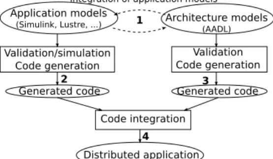
In this paper we describe an approach (see figure 1) to integrate architecture and application models. It relies on two modeling languages: an application-level language (Simulink or SCADE) and an architecture-level language (AADL [8]). Application code is generated using vendor-specific tools (step 2) and architecture-level code that uses application-level code is also generated (step 3). Merging both approaches (step 4) produces the final implementation.
Application models
(Simulink, Lustre, ...) Architecture models(AADL)
Validation/simulation Code generation
Validation Code generation
Generated code Generated code
Code integration Distributed application
integration of application models
1
2 3
4
Figure 1. Proposed development process
2
Architecture Modeling with AADL
AADL is a component-centric language which focuses on the description of the non-functional aspects of the com-ponents such as timing or memory concerns.
An AADL description is made out of hardware and
software components. The AADL standard defines basic component types that must be extended to describe a sys-tem. The software types are:data, thread, thread group, subprogram, process. The execution platform compo-nents types are memory, bus, processor, device, virtual processor, virtual bus. Finally, there is one hybrid component type (system).
Components describe well identified elements of the ac-tual architecture. The Subprogram type models application code and references another external (application) model. The Thread type models the active part of an application (such as POSIX threads). The Process type models an ad-dress space that contains the threads. The Processor type models aspects of both the processor and the operating sys-tem relevant to the non-functional properties. The mem-orytype models hard disks, RAMs, ROMs and other forms of memory. The bus type models all kinds of networks and hardware connections. Finally, the system type models composite components that are made up of hardware and software components. For example, a system may represent a board with multiple processors and memory chips.
Components are organized in a hierarchy, i.e.: compo-nents contain other compocompo-nents (called subcompocompo-nents in this case). AADL models contain a topmost system compo-nent that contains, hardware and software subcompocompo-nents and the deployment of the software to the hardware.
The interface specification of a component is called its type. An interface is a collection of features that can be con-nected to other component’s features to model their com-munication. Each component has a separate implementa-tiondescription that is populated with subcomponents and connections among them. An implementation of a thread or a subprogram can specify call sequences to other subpro-grams, thus describing the execution flows in the architec-ture.
process_producer.i
thr_producer.i thr_consumer.i
process_consumer
ethernet_bus distributed_system.i
Figure 2. Sample AADL model
AADL associates properties to model elements. Proper-ties are name/value pairs that represent components charac-teristics and constraints, such a the period of a thread, etc.
Figure 2 shows an AADL model using its graphical rep-resentation. In this model, two processes communicate through the network. Each process contains a thread, one being a producer, the other a consumer.
Interested readers can find an introduction to this lan-guage in [7].
3
Modeling functional blocks
3.1
Simulink
Simulink is one of the modeling languages of Matlab, a simulation tool commonly used in the industry. One of the key reasons for the popularity of Simulink is the math-ematical toolboxes that enable the designer to simulate key characteristics of the system.
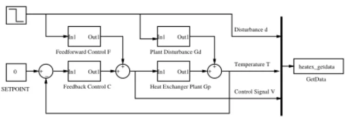
Simulink is a dataflow language. A Simulink system is composed of data-processing blocks and connections be-tween their inputs and outputs A typical model in Simulink includes both the system under control, and its associated controller. As a result, both parts of the model can be ex-ercised by the simulation engine, to focus on the evaluation of the mathematical functions.
GetData In1 Out1 In1 Out1
In1 Out1 In1 Out1 Feedback Control C ++ ++ Plant Disturbance Gd Feedforward Control F
Heat Exchanger Plant Gp 0 SETPOINT + − Disturbance d Temperature T Control Signal V heatex_getdata
Figure 3. Simulink Example - Heat Exchanger
As an example, consider the heat exchanger system de-picted in Figure 3. In this model both the controller mod-ules (Feedback Control C and Feedfordward Control F) and the controlled system (Heat Exchange Plant Gp) are present. In this example, the steps of both, the com-putations of the controller modules and the reactions of the controlled system simulations, are advanced synchronously by the simulation engine.
However, the final generated code to be used in the real system has not controlled plant code but another piece of software of hardware. Hence, we need to adapt the con-troller algorithm to synchronize with the plant. On the one hand, it needs to run periodically at a rate that can keep up with the dynamism of the plant. On the other hand, feedback loops need to be implemented to communicate its value from one activation of the controller to the next.
Both, the periodicity of the controller, and the feedback connections are part of an architectural model that comple-ments this functional model. On the one hand, the period-icity is modeled as periodic threads that call the appropriate functional code. On the other hand, the feedback loops are modeled as delayed connections that ensure consistency in the communication between the threads. All these elements are part of the concerns to be described in an AADL model.
Figure 4. SCADE code example
3.2
SCADE
“Safety Critical Application Development Environ-ment” (SCADE) defines a simple and efficient textual for-malism to design safety-critical software. SCADE relies on a graphical notation to model data flows. The design of SCADE programs is made out of computing blocks with data flows that connect blocks inputs and outputs (see fig-ure 4 for an example). State machines can also be used to control program behavior.
Applications written with SCADE can be simulated, which help the developers to test and ensure their correct-ness. SCADE can automatically generates code from the graphical notation using its code generator (kcg). This code generator outputs potentially certified C code. Such a devel-opment process help the developer to design its application and reduce certification costs. SCADE was successfully used in the industry, especially in the avionics domain.
Figure 4 depicts a SCADE sample program that adds the value of its input to a global memory. The input add input is added to the previous computed value. Then, the output add outputcontains the computed value.
However, code generated by kcg still requires manual in-tegration with other elements (such as drivers) as well as a separate toolchain for integration on target hosts. Deploy-ment/integration of verified applications in validated archi-tectures would make the development process more robust.
4
Modeling process
4.1
Application-driven process
In this approach, the functional part of the system is first designed and then, allocated to a runtime architecture. Techniques to do this include the use of bin-packing algo-rithms to allocate software to hardware, design exploration to find the best assignments, and analysis to ensure the sys-tem is schedulable. Each of these steps involves:
1. Functional blocks are defined using vendor-specific tools. These tools allow the simulation and analysis of these blocks to verify their correctness and properties.
2. An AADL runtime architecture is designed, listing processor, memory and bus components. This architecture defines hardware elements and their topology.
3. Functional blocks are imported as AADL subprogramsand data components.
4. Finally, the allocation is performed. It takes advantage of the annotations in the AADL model that includes WCET, bandwidth/memory consumption, etc.
This development process was used in our Simulink case-study, detailed in section 6.1
4.2
Architecture-driven process
In this approach, the architecture is first designed de-scribing the runtime components of the system, e.g. pro-cesses, threads, processors, etc. Then, functional blocks are then allocated to these components. This process is based on these following steps:
1. An AADL architecture is designed and list available resources (including threads with scheduling concerns, root subprograms and data types).
2. Functional blocks are implemented. Their interface should match the AADL interface.
3. AADL subprograms and data components are then refined to reference these implementations.
Such a development process was used in our SCADE case-study, detailed in section 6.2.
4.3
Integration challenges
The integration of the functional model with the runtime architecture model allows us to validate and generate the complete system.Using MDE principles (abstraction, model transformation and analysis), this creates a complete path from models to code, with integrated validation and simu-lation.
However, the model-to-code process that integrates ar-chitectural and functional model must ensure the tency of such integration. There are three types of consis-tency:
• Data representation consistency: Data must have the same representation in architecture and application models. • Source-code interoperability: Application models use a specific API to exchange data between blocks. This API must be integrated in the architecture code to import/-export data between architecture and application code.
• Semantics consistency: The integration process must preserve models semantics and data flows.
5
Supporting the process
5.1
Import application data in AADL
In Simulink or SCADE, the designer specifies the data types used on each component. This information should
be used to pre-allocate buffers to exchange data in the run-time system. For this reason, it should be integreated in AADL models so that data components of the architecture-level models reflect types used in application architecture-level models.
In AADL, data are described using the data com-ponent and their characteristics are described by adding propertiesto it. So, AADL data components must en-sure the data consistency between the application and ar-chitecture models.
For example, the modeling of an SCADE integer in AADL is achieved with a data component associated with an appropriate property (see listing 1).
1 data i n t e g e r 2 p r o p e r t i e s 3 D a t a R e p r e s e n t a t i o n => I n t e g e r ; 4
Source Language => Scade ;
5
end i n t e g e r ;
Listing 1. Map SCADE integer using AADL
5.2
Import application functions
Traditional code (written in Ada or C) integration in AADL models is achieved with the subprogram compo-nent. It models an instruction flow executed by a thread. Application-level non-functional properties are described by adding properties to AADL components. These prop-erties are reused in the process development for compila-tion or integracompila-tion purposes. To integrate applicacompila-tion-level models into AADL models, we specify modeling patterns that rely on specific properties. The mapping of SCADE or Simulink application code is described below.
5.2.1 Simulink mapping
Integrating Simulink models in AADL is achieved by adding some properties to a subprogram component:
• Source Language is set to Simulink .
• Source Name specifies the name of the Simulink block. • The Source Text property specifies the directory that contains the code generated by the Simulink code generator. Finally, we define the association between subprogram featuresand the Simulink block inputs/outputs so that the architecture model know its mapping with Simulink com-munication ports.
Listing 2 corresponds to the integration of the Heat Exchangerblock (shown in figure 3). We map this appli-cation in an AADL subprogram and specify the name of the mapped Simulink block using the Source Name prop-erty. Then, we map Simulink output signals to AADL subprogram features using the Source Name property on each feature. Here, the AADL dist feature corresponds
to the disturbance Simulink signal, the AADL temp fea-ture corresponds to the temperafea-ture Simulink signal and the AADL csignal feature corresponds to the Control SignalSimulink signal.
1 subprogram s p g s i m u l i n k 2 f e a t u r e s 3 d i s t : out parameter s i m u l i n k r e a l 4 {Source Name => ” d i s t u r b a n c e ” ;}; 5
temp : out parameter s i m u l i n k r e a l
6 {Source Name => ” t e m p e r a t u r e ” ;}; 7 c s i g n a l : out parameter s i m u l i n k r e a l 8 {Source Name => ” C o n t r o l S i g n a l ” ;}; 9 p r o p e r t i e s 10
source name => ” Heater Exchanger ” ;
11 s o u r c e l a n g u a g e => S i m u l i n k ; 12 s o u r c e l o c a t i o n => ” /path / to / s i m u l i n k−code / ” ; 13 end s p g s i m u l i n k ;
Listing 2. Simulink’s Heat exchanger in AADL
5.2.2 SCADE mapping
Importing a SCADE node with AADL is achieved using an subprogramcomponent with the following properties:
• Source Language is set to Scade.
• Source Name specifies the name of the SCADE node. • Source Location points the location of the SCADE code on the filesystem.
We also indicate the mapping of AADL features onto SCADE parameter by adding the Source Name property on each feature. The value of this property is set the their cor-responding inputs/outputs in the SCADE model.
The listing 3 shows the integration of the SCADE adder example (shown in figure 4). The property Source Name is added on each parameter to describe the mapping between the AADL subprogram features and SCADE inputs/out-puts. Here, the input parameter from the AADL compo-nent corresponds to the add input input of the SCADE node and the output parameter corresponds to the
add outputoutput of the SCADE model.
1
subprogram spg scade
2
f e a t u r e s
3
i n p u t : i n parameter i n t e g e r {Source Name => ” a d d i n p u t ” ;};
4
o u t p u t : out parameter i n t e g e r {Source Name => ” a d d o u t p u t ” ;};
5 p r o p e r t i e s 6 source name => ” i n c ” ; 7 s o u r c e l a n g u a g e =>Scade ; 8
s o u r c e l o c a t i o n => ” /path / to / scade−code / ” ;
9
end spg scade ;
Listing 3. inc SCADE node with AADL
5.3
Code generation and integration
This section details the characteristics of architecture and application generated code and explains their integration.
5.3.1 Architecture-level code overview
Architecture-level generated code provides resources to ex-ecute functional code and can be seen in three parts:
• Thread part reflects AADL thread components. This part performs calls to the application-level code, as de-scribed in the subprogram components.
• Process part creates resources (threads or shared data) and establishes communication channels with the other nodes of the distributed system.
• OS and network configuration part is generated using information from the processor and system components. It configures the underlying operating systems of each node to execute the generated code (for example, RTEMS [6] needs declarations to enable specific functionalities).
5.3.2 Application-level code overview
Application-level code generators (as in Simulink or SCADE) provides two important functionalities:
• An initialization function that instantiates resources. • A reaction function that computes outputs from inputs values. Calling this function is the execution of one step in the computation of the application model.
These code generators provide mechanisms to interoper-ate with the generinteroper-ated functions (get/put data into the appli-cation code, call the reaction function, . . . ). In our case, we use these features to exchange data between application and architecture levels and trigger application reaction.
Generated Application code (Simulink/Lustre) Thread Generated Application code (Simulink/Lustre) Process Thread Process OS and network configuration
App li c a ti on le v e l c od e Arc h it e c tu re le v e l c od e calls calls
Figure 5. Interaction between application and architecture generated code
5.3.3 Integration of the code from both generators Application level code is described using AADL subprogram components so that there is no differ-ence between traditional subprogram and application model subprograms: application code resides on top of the thread part of the architecture code, as shown in figure 5. Architecture code remains unchanged. Changes are only made in the generated subprogram: this part enables
interactions (data exchange) with application code and calls the reaction function.
To do so, the code generator creates a function from the AADL subprogram that follows this pattern:
1 It injects the in parameters of the AADL subprogram into the application.
2 It calls the reaction function of the application-level code to compute new output values.
3 It retrieves application-level outputs injects them into the AADL subprogram output parameters
Figure 6. Simulink model of our case-study
6
Case studies
During our tests, application code was generated with dedicated tools (Real-Time Workshop for Simulink, KCG for SCADE) and architecture code was generated using the OCARINAtool suite. It generates C code with the appropri-ate glue code detailed in section 5.
6.1
Simulink case-study
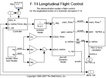
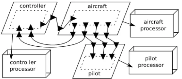
This case-study follows an application-driven process: a flight control application (illustrated in figure 6 and avail-able in Simulink releases) was divided in three parts (con-troller, aircraft control and pilot calculation) and deployed on a distributed architecture (illustrated in 7).
We take into account the requirements of the application (feedback loops, data flows, . . . ) to preserve application requirements in the architecture.
6.2
SCADE case study
The SCADE case study follows an architecture-driven process: we first designed a distributed architecture (shown
pilot aircraft controller controller processor aircraft processor pilot processor
Figure 7. Simulink case-study architecture
in figure 8) with the appropriate requirements and integrate an application model (a cruise control system and available in SCADE releases). Application inputs are simulated by a separate node (src process).
In the architecture side, one node (src process) sim-ulates application values and send them to another node through the network. This node (scade process) receives the values, computes a new value and sends it to a third node. It dst process) executes a subprogram that prints the speed value on the screen.
src_process scade_process dst_process
simulator
processor computationprocessor
command board processor
Figure 8. SCADE case-study architecture
6.3
Integration validation
We validated our approach by comparing simulation and execution. The simulated values were obtained with dedi-cated tools (Matlab or SCADE toolsuite). To collect values during execution we instrumented the code to get values sent/received over data ports. Then, we compare simu-lation and execution values according to the mapping rules between application and architecture models.
During our experiments, we found that values from sim-ulation and execution were the same. It shows the correct-ness of our approach and demonstrates that application and architecture code are correctly integrated.
7
Conclusion
In this article, we presented a full MDE approach to de-sign and implement DRE systems. We detailed different modeling approaches (architecture- or application-driven)
and explained how architecture and application models are integrated from design to implementation. Code was au-tomatically generated from integrated models to create dis-tributed applications without manual coding. This develop-ment process avoids error from traditional coding methods and preserves the analysis results from the modeling tools.
An additional advantage of using AADL is the continu-ous flow of analysis tools that are based on this language. That is, both the research community and the industry are using AADL as a platform to explore new analysis tech-niques. The use of these analysis tools, combined with an appropriate development process (such as the one detailed in this paper) would ease DRE systems development.
References
[1] P. Binns, M. Englehart, M. Jackson, and S. Vestal. Domain-specific software architectures for guidance, navigation and control. 6(2):201–227, June 1996. [2] K. Hales. Matlab/simulink model as a tool for process
design and commissioning. May 2004.
[3] R. H. Martin and D. Raffo. A model of the software de-velopment process using both continuous and discrete models. Software Process: Improvement and Practice, 5(2-3):147–157, 2000.
[4] N. Medvidovic and R. N. Taylor. A classification and comparison framework for software architecture de-scription languages. IEEE Transactions on Software Engineering, 26:70–93, 2000.
[5] J. Miller and J. Mukerji. Mda guide version 1.0.1. Tech-nical report, Object Management Group (OMG), 2003. [6] OARCorp. Rtems - http://www.rtems.com.
[7] Peter H. Feiler, David P. Gluch, and John J. Hudak. The Architecture Analysis and Design Language (AADL) : An introduction. Technical report, 02 2006.
[8] SAE. Architecture Analysis & Design Language v2.0 (AS5506), September 2008.
[9] D. C. Schmidt. Guest Editor’s Introduction: Model-Driven Engineering. Computer, 39(2):25–31, 2006.