O
pen
A
rchive
T
OULOUSE
A
rchive
O
uverte (
OATAO
)
OATAO is an open access repository that collects the work of Toulouse researchers and
makes it freely available over the web where possible.
This is an author-deposited version published in : http://oatao.univ-toulouse.fr/
Eprints ID : 4689
To link to this articl
e : DOI :10.1149/1.3430105
URL :http://dx.doi.org/10.1149/1.3430105
To cite this version :
Krisuyk, Vladislav and Gleizes, Alain and Aloui,
Lyacine and Turgambaeva, Asiya and Sarapata,
Bartosz andPrud'Homme, N. and Senocq, François and Samélor,
Diane and Zielinska-Lipiec, Anna and De Caro, D. and Vahlas,
Constantin ( 2010) Chemical vapor deposition of iron, iron
carbides, and iron nitride films from amidinate precursors.Journal
of The Electrochemical Society (JES), vol. 157 (n° 8). D454-D461.
ISSN 0013-4651
Any correspondance concerning this service should be sent to the repository
administrator: staff-oatao@inp-toulouse.fr
.
Chemical Vapor Deposition of Iron, Iron Carbides, and Iron
Nitride Films from Amidinate Precursors
Vladislav Krisyuk,a,bAlain N. Gleizes,aLyacine Aloui,aAsiya Turgambaeva,a,b Bartosz Sarapata,a,cNathalie Prud’Homme,aFrançois Senocq,a
Diane Samélor,a Anna Zielinska-Lipiec,cDominique de Caro,d and Constantin Vahlasa,z
a
Centre Interuniversitaire de Recherche et d’Ingénierie des Matériaux, Ecole Nationale Supérieure d’Ingénieurs en Arts Chimiques et Technologiques, 31432 Toulouse Cedex 4, France
b
Nikolaev Institute of Inorganic Chemistry, Siberian Branch of the Russian Academy of Science, Novosibirsk 630090, Russia
c
Akademia Górniczno-Hutnicza University of Science and Technology, PL-30 059 Krakow, Poland
d
Laboratoire de Chimie de Coordination, CNRS, 31077 Toulouse Cedex 4, France
Iron bis共N,N⬘-diisopropylacetamidinate兲 关Fe2共-iPr-MeAMD兲2共2-iPr-MeAMD兲2兴 and iron bis共N,N⬘-di-tert-butylacetamidinate兲
关Fe共tBu-MeAMD兲
2兴 were used as precursors for the metallorganic chemical vapor deposition 共MOCVD兲 of iron-containing
compounds including pure iron, iron carbides, Fe3C and Fe4C, and iron nitrides Fe4C. Their decomposition mechanism involves
hydrogen migration followed by dissociation of the Fe–N bond and the release of free hydrogenated ligand共HL兲 and radicals. Surface intermediates are either released or decomposed on the surface providing Fe–N or Fe–C bonds. MOCVD experiments were run at 10 Torr, in the temperature ranges of 350–450°C with Fe2共 −iPr-MeAMD兲2共2-iPr-MeAMD兲2and 280–350°C with
Fe共tBu-MeAMD兲2. Films prepared from Fe2共 −
i
Pr-MeAMD兲2共2
-i
Pr-MeAMD兲2contain Fe, Fe3C, and Fe4C. Those prepared
from Fe共tBu-MeAMD兲
2contain Fe, Fe3C, and also Fe4C or Fe4N, depending on the temperature and hydrogen to precursor ratio
共H/P兲 in the input gas. The room-temperature coercive field of films processed from Fe共tBu-MeAMD兲
2is 3 times higher than that
of the high temperature processed Fe4N films.
Iron-based metallic and ceramic films have a wide range of ap-plications and there is an unfailing interest in developing and im-proving techniques for the processing of such films with innovative phase compositions. To mention but a few examples, the use of Fe films is foreseen in metallurgical applications;1films containing iron nitrides present not only mainly magnetic but also tribological and corrosion-resistant properties共Ref. 2 and references therein兲. Iron carbides have attracted attention due to their high hardness and melt-ing point.3Although physical vapor deposition is widely used for these purposes, metallorganic chemical vapor deposition共MOCVD兲 is reputed to be a flexible and economically competitive method because it combines conformal coverage with high deposition rates and mild deposition conditions.4However, MOCVD of nitride and of metallic films has not been widely applied yet. Typical drawbacks are the contamination with carbon and the difficulty to control the composition and the microstructure of the films.
In the frame of an ongoing project, the authors are presently investigating the preparation of multimetallic films by co-depositing Fe and Al with the MOCVD technique. Such intermetallic systems can be used for the processing of coatings containing iron alu-minides and more generally complex metallic alloys presenting unique combinations of properties.5To meet this objective, the se-lection of appropriate precursors is not simply limited to identifying metal complexes with similar volatilities and similar decomposition temperatures. Ideally, precursors for the chemical vapor deposition 共CVD兲 of metals should be selected and treated so as to be cleanly decomposed共clean cleavage, stable ligands, ligand fragments, etc.兲 共see, for instance, Ref. 6兲. Co-depositing several metals requires
considering the different chemistries of the metals. This is the case for a system containing aluminum and d-transition metals such as the Fe–Al couple. The highly electropositive character of aluminum excludes the presence of the most electronegative elements such as oxygen or fluorine in the precursors of both aluminum and the com-panion metal共s兲. Similarly, the affinity of iron to carbon leads to set
Fe–C bonds containing precursors aside. Finally, ligand exchange reactions between the precursors must be avoided because they may induce dramatic volatility decrease. It is therefore necessary to test the selected precursors separately and then in pairs 共see, for in-stance, Ref.7兲. Consequently, one motivation of this work was to
investigate an original process for the MOCVD of the Fe films. Compared with other metals, few open scientific publications refer to the thermal MOCVD of pure iron films. Fe共Cp兲2,1,8,9 Fe共CO兲5,10-14 Fe2Cp2共CO兲4,15 Fe共COT兲共CO兲3,16 and 关共arene兲
共diene兲Fe0兴 17are known as iron precursors, but they do not meet
the prerequisites of no oxygen and no Fe–C bond. Fe关N共SiMe3兲2兴3
is worth testing, but the reported deposition temperature of 325°C18 may be too high for the purpose of the co-deposition with Al. Fe共II兲 dihydride H2Fe关P共CH3兲3兴4yielded pure␣-Fe films between 230 and
280°C, but limited information was provided on the process itself and the obtained material.19 Finally, Lim et al. showed that some transition-metal amidinates are volatile20and can be used as precur-sors for the atomic layer deposition共ALD兲 of transition-metal thin films.21 Based on the latter papers, copper amidinates have been recently successfully tested for the deposition of copper.22
A parallel motivation of this work concerns the investigation of innovative MOCVD routes for the processing of iron nitrides. The motivation originates from the intrinsic magnetic properties of such materials, especially ␥
⬘
-Fe4N, combined with their high electrical conductivity and their chemically inert and mechanically hard sur-faces共Ref. 23 and 24 and references therein兲. Line-of-sight tech-niques such as thermal evaporation, reactive sputtering, and laser ablation have been employed for the processing of iron nitride films 共Ref.25and references therein兲. Alternatively, vapor-phase epitaxy involving iron trichloride共FeCl3兲 and ammonia 共NH3兲 allowed the production of Fe4N epitaxial layers, with the noticeable drawbacksof high processing temperature共600°C兲 and aggressive halide-based chemistry.26 Few papers deal with the CVD of iron nitrides. Funakubo et al. reported on the formation of ␥
⬘
-Fe4N from bis-cyclopentadienyl iron and NH3/H2/CO2above 700°C.27Roberson et al. reported on the growth of Fe3N from iron acetylacetonate andanhydrous NH3above 600°C.2
z
The present paper deals with the investigation of two iron amidinates as precursors for the MOCVD of Fe and Fe4N: 共1兲 dinuclear iron bis共N,N
⬘
-diisopropylacetamidinate兲关Fe2共-iPr-MeAMD兲2共2-iPr-MeAMD兲2兴 and 共2兲 mononuclear
iron bis共N,N
⬘
-di-tert-butylacetamidinate兲 关Fe共tBu-MeAMD兲2兴.20 These are nonoxygenated metallorganic complexes with ligand– metal bonding through Fe–N bonds共Fig.1兲. Lim et al. showed thatcompound 2 could be used for the ALD of pure iron films.21 In what follows, information on the thermal behavior of the two precursors, investigated by in situ mass spectrometry, is first re-ported. The characteristics of the MOCVD processed films are then detailed, focusing on their elemental and phase composition, and morphology. Finally, the room-temperature magnetic properties of the films are reported and discussed.
Experimental
Precursor investigation.— Compounds 1 and 2 were synthesized by NanoMePSe by appropriately adapting the protocol of Lim et al.20They were used without further purification. Both compounds are extremely sensitive to air and light. Upon storage in a metallic glove box under a continuously purified argon flow, they slowly decomposed: The green powder of precursor 1 tarnished and the white powder of precursor 2 turned gray. The compounds must be kept in sealed ampoules at 4°C.
The gas-phase thermal decomposition of the precursors was stud-ied by a technique which combines Knudsen effusion and mass
spectrometric measurements of the gas-phase composition. The ex-perimental details have been described elsewhere.28This investiga-tion used a time of flight mass spectrometer directly fed by an input system that imitates a CVD reactor. 5 mg of the compound was sealed in a glass ampoule under inert gas and heated in the evapo-rator at 90 and 70°C for compounds 1 and 2, respectively. The evaporator temperature was kept constant, and the vapors were transported to the miniature CVD reactor through a heated pipeline. During the experiment, the reactor temperature was progressively raised from the temperature of evaporation to 400°C with a heating rate of 5°/min. The reaction mixture was sampled through the effu-sion hole共0.2 mm兲 from the reactor into the mass analyzer. Mass spectra were recorded at ionizing electron energies ca. 70 eV. The temperature dependence of the gas-phase composition was derived from the mass spectra.
Deposition.— The CVD experiments were conducted in two, stagnant-flow, vertical, tubular, cold wall reactors of similar configu-rations. Reactor A was composed of a glass tube containing an in-ductively heated, 20 mm diameter stainless steel susceptor. It was used for the initial screening of the two precursors. Reactor B was used for the processing of multimetallic coatings. It was composed of a stainless steel body and contained a resistively heated, 60 mm diameter stainless steel susceptor. A detailed description of the setup is provided in Ref.29. A showerhead above the susceptor ensured homogeneous flow of the reactants on the surface of the substrates. The larger susceptor in reactor B allowed expanding the number and types of substrates processed in one run. The deposition from pound 1 was investigated in reactor A; the deposition from com-pound 2, which proved to be the more promising of the two precur-sors for the co-deposition of multimetallic films, was investigated in both reactors. The base pressure for both reactors was 1.0 ⫻ 10−6 Torr. Flow thermal and hydrodynamic characteristics were
calculated so as to get laminar flows and similar operation condi-tions in either reactor共Ref.29and unpublished results兲.
Polycrystalline copper disks共10 mm in diameter, 1 mm thick兲 were used as substrates. The disappearance of copper color was optically tracked to access film growth onset. Before deposition, the substrates were polished with a diamond paste down to 5 m. They were cleaned ultrasonically in acetone and anhydrous ethanol. Pure nitrogen 共99.998%兲 and pure hydrogen 共99.999%, Air Products兲 were fed through computer-driven mass flow controllers. The former was used both as carrier gas through the precursor container and as dilution gas. The deposition pressure was 10 Torr and the tempera-ture of the substrates was in the range 150–450°C. The precursor container was maintained at 95 and at 85°C for precursors 1 and 2, respectively. Deposition was run for 1–4 h, depending on the oper-ating conditions. TableIsummarizes the flow rate conditions. The main difference in the processing conditions between reactors A and B is the ratio of the hydrogen to precursor concentration共hereafter referred to as H/P兲. Because the saturated vapor pressure vs tem-perature values are not actually available for these new compounds, it is not possible to quantify P and, subsequently, the H/P ratio. For this reason, it can only be mentioned that the H/P ratio is 3 to 4 times higher in reactor B than in A.
The deposited phases were identified by grazing incidence X-ray diffraction共GIXRD兲 with a Siefert 3000 diffractometer 共Cu K␣ ra-diation; grazing angle = 2–3°; 2 step = 0.04°兲. Surface and cross section morphologies were investigated by a scanning electron
mi-e www.nanomeps.fr N N N N Fe Fe N N N N C H3 CH3 C3H7 C3H7 C3H7 C3H7 CH3 CH3 C3H7 C3H7 C3H7 C3H7 (a) Fe N N N N C4H9 C4H9 C4H9 C4H9 CH3 C H3 (b)
Figure 1. Developed formulas of 共a兲 bis共N,N⬘ -diisopropylacetamidin-ate兲iron共II兲 共1兲, and of 共b兲 bis共N,N⬘-di-tert-butylacetamidinate兲iron共II兲 共2兲.
Table I. Flow rate conditions for reactors A and B. Flow rate
共sccm兲 Q共H2兲 Q共N2, carrier兲 Q共N2, dilution兲 Q共total兲
Precursor 1 2 1 2 1 2 1 2
Reactor A 50 80 20 20 30 0 100 100
croscope共SEM兲 with a LEO 435 VP instrument and a field-emission gun共FEG兲 equipped JEOL JSN6700F instrument. Elemental analy-ses of the films were performed by electron probe microanalysis 共EPMA兲 using a CAMECA SX50 instrument. The films were sub-mitted to X-ray photoelectron spectrometry 共XPS兲 on an ESCALAB-MkII 共VG Scientific兲 instrument. The photoelectron spectra were excited using non-monochromatized Mg K␣ radiation 共h = 1253.6 eV兲 with a total instrumental resolution of ⫾0.5 eV. Analyses were performed after etching of the film superficial layers with Ar ions. The room-temperature magnetic properties of the films were characterized using a Quantum Design MPMS2 superconduct-ing quantum interference device magnetometer. The magnetic field was applied parallel to the film plane. The diamagnetic contribution from the substrate was negligibly small compared to the magnetiza-tion of the films.
Results
Characterization and thermal behavior of the precursors.— The mass spectra of the two compounds are characterized by the occur-rence of relatively intense molecular peaks corresponding to the monomer关FeL2兴+and to the free ligand关HL兴+. There are no peaks
at mass-to-charge共m/z兲 ratios higher than the value expected for FeL2, i.e., 338 amu for compound 1 and 394 amu for compound 2.
This was expected for compound 2, which is monomeric in the solid state.20Compound 1 is dimeric in the solid state,20so that additional studies such as vapor pressure measurement are needed to confirm the monomeric structure in the gas phase.
Figures 2 and 3 show the mass spectra ion peak intensity vs
temperature for compounds 1 and 2, respectively. Before comment-ing, it is worth noting that the observed gaseous products did not depend on whether hydrogen had been added or not.
For compound 1关Fig.2, L =共C3H7兲NC共CH3兲N共C3H7兲兴, no ma-jor changes occur in the temperature range 110–160°C共not shown兲. Further temperature increase results in the decomposition of the compound and in the ensuing intensity decrease in the关FeL2兴+peak.
At 250°C, the intensity is close to the background, indicating that the decomposition is maximal. The main gaseous compounds are the free ligand HL 共m/z = 142兲, acetonitrile 共m/z = 41兲, and 共CH3兲2CHNH共m/z = 58兲.
Figure3shows the mass spectra ion peak intensity vs tempera-ture for compound 2 关L = 共C4H9兲NC共CH3兲N共C4H9兲兴 in the pres-ence of hydrogen. Decomposition of compound 2 starts at 150°C as proved by a considerable decrease in the intensity of the initial com-pound ion peaks. Decomposition is maximal at 250°C. The main gaseous compounds are the free ligand HL共m/z = 170兲, CH3CN 共m/z = 41兲, C4H8共m/z = 56兲, C4H9共m/z = 57兲, and 共CH3兲2CHNH
共m/z = 58兲. The evolution of the intensity of the molecular peak is not sharp. This may be attributed to the relatively low vaporization stability of the compound. Similarly, the curves corresponding to 关HL兴+,关CH
3CN兴+, and关共CH3兲2CHNH兴+have complex profiles
be-cause the ions originate both from the thermal decomposition of FeL2 when the appropriate temperature is reached and from the fragmentation of FeL2and of some products共e.g., HL兲 under
elec-tron impact.
Elemental analysis of the films.— TableIIshows the carbon and nitrogen contents of the films as determined by EPMA and the main
140 160 180 200 220 240 260 280 300 320 340 360 380 400 In tens ity (arbitrary unit s) (CH3)2CHNH CH3CN HL FeL2 Temperature,oC
Figure 2. Temperature dependence of gas-phase composition upon decom-position of compound 1 关L = 共C3H7兲NC共CH3兲N共C3H7兲兴. The lines are
guides for the eyes.
80 100 120 140 160 180 200 220 240 260 280 300 HL FeL2 H2 CH3CN (CH3)2CHNH R In ten sit y (ar bi trary un its ) Temperature,oC
Figure 3. Temperature dependence of gas-phase composition upon decom-position of compound 2 in the presence of hydrogen关R = tert-butyl radical, C4H9; L = RNC共CH3兲NR兴. The lines are guides for the eyes.
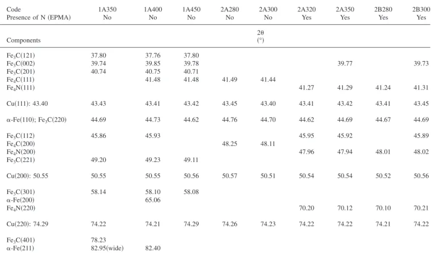
Table II. Carbon and nitrogen content and identified phases of the films, determined by EPMA and XRD, respectively (see text for sample code).
Code
Tdeposition
共°C兲 共atom %兲C 共atom %兲N Identified phases Possible additional phases
1A350 350 24 0 Fe3C Fe 1A400 400 28 0 Fe, Fe3C, Fe4C — 1A450 450 33 0 Fe3C, Fe4C Fe 2A280 280 18 0 Fe4C Fe, Fe3C 2A300 300 18 0 Fe4C Fe, Fe3C 2A320 320 15 7 Fe3C, Fe4N Fe 2A350 350 17 7 Fe3C, Fe4N Fe 2B280 280 12 9 Fe4N Fe, Fe3C 2B300 300 19 7 Fe3C, Fe4N Fe
phases identified by GIXRD 共see next paragraph兲. In this and the following tables, sample code shows the precursor 共1 or 2兲, the reactor共A or B兲, and the temperature of deposition in degrees Cel-sius. The average thickness of films was approximately 250–300 nm. The oxygen content was below the EPMA detection limit. XPS was performed on as-processed films. From the decomposition of XPS Fe 2p and C 1s peaks and from literature data for iron-containing films,30 the films contained iron oxide 共Fe 2p3/2 at
⬃712 eV兲 and graphitic and organic carbon as minority compo-nents. Iron oxides are considered as surface contaminants because they were most probably formed when the samples were exposed to ambient atmosphere. Depth profile analyses revealed uniform com-position in the films共to the extent of the zones sputtered with low energy Ar ions兲 except surface contaminants. From GIXRD and XPS 共vide infra兲, the main iron-based deposited species are iron carbides共Fe3C, Fe4C兲, iron nitride Fe4N, and metallic iron. TableII
shows that nitrogen was detected in four films grown from precursor 2 at low H/P ratio at 320 and 350°C, and at high H/P ratio at 280 and 300°C.
XRD.— GIXRD patterns for films prepared from compounds 1 and 2 are presented in Fig. 4 and 5, respectively. Table III is a synoptic of the 2 angles calculated for copper 共a = 3.6078 Å, F-type lattice兲 and measured on the X-ray patterns up to 80°. There is a strong fit between the calculated and observed 2 values for the diffraction lines共111兲, 共200兲, and 共220兲 from the copper substrate, and this allows using it as an internal 2 standard. Neither iron nor copper oxides were detected. The patterns contain lines attributable to ␣-Fe 共JCPDS file no. 6-696兲 and Fe3C 共JCPDS file no. 34-1兲. They also contain lines attributable to Fe4C or Fe4N depending on
the sample. Fe4C has two allotropic forms.3,31,32The observed form
is isostructural with ␥
⬘
-Fe4N 共JCPDS file no. 6-0627兲: primitiveTable III. Peak positions in GIXRD patterns of deposited films.
Code 1A350 1A400 1A450 2A280 2A300 2A320 2A350 2B280 2B300
Presence of N共EPMA兲 No No No No No Yes Yes Yes Yes
Components 2 共°兲 Fe3C共121兲 37.80 37.76 37.80 Fe3C共002兲 39.74 39.85 39.78 39.77 39.73 Fe3C共201兲 40.74 40.75 40.71 Fe4C共111兲 41.48 41.48 41.49 41.44 Fe4N共111兲 41.27 41.29 41.24 41.31 Cu共111兲: 43.40 43.43 43.41 43.42 43.45 43.40 43.41 43.42 43.41 43.45 ␣-Fe共110兲; Fe3C共220兲 44.69 44.73 44.62 44.76 44.70 44.62 44.69 44.67 44.69 Fe3C共112兲 45.86 45.93 45.95 45.92 45.89 Fe4C共200兲 48.25 48.11 Fe4N共200兲 47.96 47.94 48.01 48.02 Fe3C共221兲 49.20 49.23 49.11 Cu共200兲: 50.55 50.55 50.55 50.56 50.57 50.51 50.54 50.54 50.52 50.56 Fe3C共301兲 58.14 58.10 58.08 ␣-Fe共200兲 65.06 Fe4N共220兲 70.20 70.12 70.10 70.21 Cu共220兲: 74.29 74.22 74.21 74.29 74.26 74.23 74.22 74.22 74.21 74.22 Fe3C共401兲 78.23 ␣-Fe共211兲 82.95共wide兲 82.40
Table IV. Decomposition of the Fe 2p3Õ2and C 1s XPS peaks of films prepared from compound 2: BE and energy drifts are in eV. Energy drifts
are measured from peak Fe1 for Fe peaks and peak C2 for C peaks.
Peak code
Fe1vFe + Fe nitrides Fe2vFe carbides Fe3vFe oxides C1vC carbides C2 = graphitic C C3 = organic C 2p3/2BE
atom % Fe1/Fetotal
2p3/2BE共E drift兲 atom % Fe2/Fetotal
2p3/2BE共E drift兲 atom % Fe3/Fetotal
1s BE共E drift兲 atom % C1/Ctotal 1s BE atom % C2/Ctotal 1s BE共E drift兲 atom % C3/Ctotal Sample 2A260 706.6 708.3共1.7兲 710.6共4.0兲 — — — 46 32 22 2A280 706.5 708.3共1.8兲 710.7共4.2兲 282.5共⫺1.5兲 284.0 285.9共1.9兲 43 38 19 50 36 14 2A300 706.6 708.3共1.7兲 710.8共4.2兲 283.1共⫺1.9兲 285.0 287.6共2.6兲 42 45 13 71 17 12 2A320 707.6 709.3共1.7兲 711.2共3.6兲 283.9共⫺1.9兲 285.8 289.1共3.3兲 43 32 25 52 32 16 2A350 707.7 709.6共1.9兲 711.7共4.0兲 283.3共⫺1.4兲 284.7 No peak 36 39 25 37 63
cubic lattice, with a = 3.790 Å for Fe4N 33 and a = 3.678 Å for Fe4C.3,31There is no recorded X-ray diffraction 共XRD兲 pattern for
Fe4C in the JCPDS database. The calculated Fe4C diffraction pattern
can be deduced from Fe4N by considering the difference in the cell constant. Using the copper substrate as an internal 2 standard, the lines at 41.25⫾ 0.02 and 47.99 ⫾ 0.02° were indexed as Fe4N共111兲 and Fe4N共200兲 reflections and those observed at 41.45⫾ 0.02 and 48.19 ⫾ 0.04° as Fe4C共111兲 and Fe4C共200兲 re-flections共Table III兲. The systematic discrepancy of 0.2° between
corresponding diffraction angles is significantly larger than the dif-ferences between the calculated and observed copper angles共0.05° at most兲. Therefore, the distinction between Fe4C and Fe4N
be-comes unambiguous.
There is an ambiguity in the determination of metallic iron be-cause the␣-Fe strongest reflection 共110兲 at 44.67° and Fe3C strong
reflection共220兲 at 44.59° almost overlap. Therefore, the reflection observed at ca. 44.6–44.7° in every pattern can be attributed to either Fe and Fe3C. Moreover, the Fe3C strongest reflections at 43.77 and 42.90° may be hidden by the Cu共111兲 reflection at 43.40°. From the GIXRD patterns shown in Fig.4and the data extracted from them and analyzed in TableIII, the films processed from com-pound 1 systematically contain Fe3C. For the film deposited at 400°C共1A400兲, two weak reflections at 2 = 65.06 and 82.40° can be attributed to␣-Fe共200兲 and ␣-Fe共211兲, respectively. For the film deposited at 350°C共1A350兲, reflection 共200兲 does not show, and reflection共211兲 may be included in the wide reflections observed at 82.95°. For the film deposited at 450°C共1A450兲, there is no iron reflection except for the one that is also attributable to Fe3C. Finally,
for the films deposited at 400 and 450°C, there is a reflection at 41.48° that matches the Fe4C strongest reflection共111兲.
Despite the narrow temperature range investigated, the films de-posited from compound 2 present noticeable differences 共Fig. 5, TableIII兲. The possible presence of metallic iron can only be
de-duced from the line ca. 44.7°, which may also belong to Fe3C. Lines
at 39.7 and 45.9° indicate the presence of Fe3C in the films prepared
at 320 and 350°C at low H/P, and at 300°C at high H/P ratio. The patterns of the films prepared at 280 and 300°C at low H/P ratio show lines from Fe4C, while the other four patterns for the films
prepared both at high and low H/P ratios show lines from Fe4N. From the intensity of reflection共111兲, Fe4N appears as the main component and is markedly共111兲-oriented. The films showing the X-ray pattern of Fe4N are those in which nitrogen was evidenced by
EPMA共TableII兲.
The weak intensity of most reflections and the overlap among some of them preclude any attempt to use the XRD patterns to quantitatively or even semiquantitatively analyze the three-phase mixture in the films.
XPS analysis.— TableIVshows the decomposition of Fe 2p3/2
peaks for five films prepared from compound 2 at low H/P values in the temperature range 260–350°C. The Fe peak was decomposed into four peaks. The first one共Fe1兲 at ca. 707–708 eV is attributed to metallic iron and Fe4N because it has been reported that the Fe 2p3/2binding energy共BE兲 in iron nitrides is too close to that of the metal to be used to distinguish a nitride from␣-Fe.34This point has been confirmed from the XPS analyses of amorphous␥
⬘
-Fe4N thin films by Fehlner et al.35and from the investigation of the elec-tronic structure of ultrathin␥⬘
-Fe4N共100兲 films by Navio et al.36,37The second peak 共Fe2兲 at ca. 708–709 eV was attributed to the carbides FenC共n = 3, 4兲. The other two peaks at ca. 710–712 and
713–714 eV were attributed to iron oxides共Fe3兲 and to the shake-up satellite, respectively. The C 1s peak was decomposed in three peaks 共TableIV兲, namely carbides 共C1兲, graphitic carbon 共C2兲, and other,
e.g., organic carbon共C3兲.
The atomic ratios Fe1/Fetotal, Fe2/Fetotal, Fe3/Fetotal, C1/Ctotal,
C2/Ctotal, and C3/Ctotal, where Fetotaland Ctotalstand for total iron
and carbon contents, respectively, were deduced from their respec-tive peak surface areas. They are reported in TableIV. The surface-generated iron oxide covers the other iron species. Therefore, the percentage of iron oxides共Fe3/Fetotal兲 is most likely overestimated
with regard to other iron species共Fe1/Fetotaland Fe2/Fetotal兲 due to
the relatively weak information depth of XPS.
From the XRD, the films deposited at 260, 280, and 300°C do not contain Fe4N. The peak observed at ca. 707.0 eV ascertains the presence of metallic iron. The ratio Fe2/Fetotalincreases with
depo-sition temperature. The films deposited at 320 and 350°C do contain Fe4N from the XRD. The presence of nitrogen in as-deposited films was proved by EPMA共TableII兲. However, no N 1s XPS peak was
observed, probably because Fe4N was decomposed upon etching the
surface of the films. The XPS peak at ca.707 eV may thus be attrib-uted to metallic iron present before the etching and to metallic iron formed upon etching. TableIVshows that the formation of Fe4N at
320°C is marked by the decrease in the atomic ratios Fe2/Fetotaland
C1/Ctotalfrom 0.45 to 0.32 and from 0.71 to 0.52, respectively.
Film morphology.— The films deposited on well-polished cop-per present a gray, mirrorlike metallic surface. This morphology is more pronounced for the films processed from precursor 2. Figure6
shows surface SEM micrographs of the films deposited from precur-sor 1, at 350°C共Fig.6a兲 and at 400°C 共Fig.6b兲. Figure7shows the micrographs for the films deposited from precursor 2, at 280°C共Fig.
7a兲 and at 350°C 共Fig.7b兲. When deposited at a temperature below
300°C, the films are made of densely packed nanocrystallites 共size ⬍ 100 nm兲, independently of the precursor. This nanostruc-ture results in films with a remarkably smooth surface. A compari-son between the films deposited at 350°C from precursors 1 and 2 共Fig.6aand7b, respectively兲 reveals different microstructures. The film deposited from precursor 1 shows poorer crystallinity than the one deposited from precursor 2. The former mainly contains Fe3C,
30 40 50 60 70 80 90 100 1A450 1A400 1A350 2 θ Fe3C Fe ↓↓ ↓↓ ↓↓ ↓↓ ↓↓ 30 40 50 60 70 80 90 100 1A450 1A400 1A350 2 θ Fe3C Fe ↓↓ ↓↓ ↓↓ ↓↓ ↓↓
Figure 4. 共Color online兲 XRD analysis of the films deposited from com-pound 1 on copper共 ↓ 兲 substrates.
30 40 50 60 70 80 90 100 Fe3C ↓ ↓ ↓ ↓ ↓ Fe Fe4N 2A280 2A300 2A320 2A350 2B280 2B300 2θ 30 40 50 60 70 80 90 100 Fe3C ↓ ↓ ↓ ↓ ↓ Fe Fe4N 2A280 2A300 2A320 2A350 2B280 2B300 2θ
Figure 5. XRD analysis of the films deposited from compound 2 on copper 共 ↓ 兲 substrates.
while the film prepared from precursor 2 at 350°C共Fig.7b兲 is well
crystallized and shows the具111典 texture of Fe4N evidenced by the XRD pattern共Fig.5兲. The use of different deposition temperatures
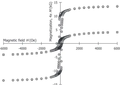
and of two precursors results in striking differences among the mi-crostructures of the processed films. This observation is correlated with the change in the composition of the films as discussed below. Magnetic properties.— Figure 8 shows 4M-H loops for the 1A400 and 2A320 films. For the 1A400 film which contains Fe3C and␣-Fe as a presumably additional phase, saturation magnetization 共4Ms= 4.1 kG兲 and coercive field 共Hc= 180 Oe兲 values are
similar to those recently reported for Fe3C/␣-Fe powders obtained by reaction milling.38 The magnetization curve recorded for the 具111典-textured ␥
⬘
-Fe4N film共2A320兲 exhibits a saturationmagneti-zation of 4Ms= 13.6 kG and a coercive field of Hc= 130 Oe.
The saturation magnetization value is lower than that of the bulk value for pure␥
⬘
-Fe4N共18–21 kG兲.39This difference may beattrib-uted to size effects, because at room temperature, the 4Msdrops with particle size.40It may also be due to the presence of free carbon in the film. The decrease in the saturation magnetization due to the presence of free carbon has already been demonstrated for the MOCVD processed Ni films.41The presently reported Hcvalue共130
Oe兲 is much higher than that for the ␥
⬘
-Fe4N共001兲-oriented films grown on MgO共001兲 or MgO共111兲 substrates 共in the 35–45 Oe range兲.42This difference can be assigned to the morphology of thefilms. Oriented films on MgO共001兲 or MgO共111兲 exhibit large grains in which spins are easily arranged. The MOCVD processed films containing ␥
⬘
-Fe4N exhibit small crystallites for which domain walls are probably harder to move.1 µm
(a) 1 µm 1 µm 1 µm 1 µm (b)Figure 6. SEM-FEG surface micrographs of films deposited from compound 1 at共a兲 350 and 共b兲 400°C.
(a)
(b)
Figure 7. SEM-FEG surface micrographs of films deposited from compound 2 at共a兲 280 and 共b兲 350°C.
Magnetic fieldH(Oe)
-6000 -4000 -2000 0 2000 4000 6000 Magnet izat ion , 4π M (k G ) -15 -10 -5 0 5 10 15
Figure 8. Magnetization 共4M兲 and magnetic field 共H兲 loops of films 1A400共squares兲 and 2A320 共circles兲.
Discussion
The films deposited from compound 2 contain less carbon-containing species than those processed from compound 1. More-over, compound 2 gives a lower onset deposition temperature and higher growth rate共detailed results on growth rates from the two precursors were published in Ref. 43兲. For these reasons,
Fe共tBu-MeAMD兲2appears as a more interesting precursor for
Fe-containing films than Fe2共iPr-MeAMD兲4. The affinity of Fe to C is responsible for the formation of Fe3C in most investigated
condi-tions. There exist, however, processing conditions for which either metallic Fe or Fe4N and Fe4C are also formed. Fe4N and Fe4C are
isostructural compounds. Their crystal structure is a primitive cubic lattice with four Fe atoms and one N共C兲 atom per cell, in a semi-antiperovskite-type structure共FeXFe3with X = N or C兲. The unit cell constants differ by ca. 3% only. Therefore, their identification by means of XRD is not straightforward. In this study, the use of X-ray reflections from the copper substrate as Bragg angles internal standard removed this difficulty.
This is a report on CVD of Fe4C while, as mentioned in the Introduction, there are but a few papers on CVD of Fe4N. Both
Funakubo et al.27and Takahashi et al.26operated at high temperature and atmospheric pressure conditions with complex gas phases in-volving separate precursors for Fe and N. The process reported in the present work operates in significantly simpler conditions.
The formation of Fe4N in the film is compatible with the analysis
of the mass spectrometric data on gas-phase composition upon ther-mal decomposition of compound 2. Based on these data, Fig. 9
resumes the following mechanism which is proposed for the decom-position of compound 2共all conversions take place on the surface兲: 共i兲 migration of H from one ligand to another, dissociation of the Fe–N bond, and release of free ligand HL into the gas phase;共ii兲 decomposition of remaining关Fe共L–H兲兴 with 共a兲 release of the radi-cal HNCH共CH3兲2共m/z = 58兲 in the gas phase, formation of carbon
and of the surface intermediate关Fe–C共CH3兲 = NR兴, and 共b兲 release of methylpropene共CH3兲2CvCH3共m/z = 56兲 in the gas-phase and
formation of the surface intermediate关Fe–NvC共CH3兲NR兴; and 共iii兲
decomposition of the surface intermediates with the release of ac-etonitrile CH3CN 共m/z = 41兲 and tert-butyl radical R 共m/z = 57兲 and formation of共a兲 Fe–N and 共b兲 Fe and C on the surface. Migra-tion of H from one ligand to another after chelate-ring opening is the typical process for metal–chelate complexes with organic ligands.28 The formation of organic products with an m/z lower than for the ligand indicates that a pure reduction of the compound by hydrogen does not take place. This is also supported by recent literature data on the decomposition of copper amidinates on Ni surface under high vacuum conditions.44
Conclusion
This reported study of iron amidinates tentatively used as precur-sors for the MOCVD of iron and iron nitrides. Iron amidinates were
chosen because they contain no oxygen atoms and no Fe–C bonds. Between the two alkylacetamidinates retained, the共1兲 isopropyl de-rivative is dinuclear in the solid state and the共2兲 tert-butyl deriva-tive is mononuclear. Mass spectrometry showed them to be mono-nuclear in the gas phase. Compound 1 proved to provide more carbon-based species than compound 2.
Fe and Fe3C were present in the films. The films also contained
either Fe4C or Fe4N depending on the temperature and the hydrogen
to precursor concentrations in the input gas.
This work may be considered as a screening approach for the use of iron amidinates as precursors for preparing iron-based materials by MOCVD. The determination of the appropriate processing win-dow for the deposition of either metallic Fe or Fe4N, or even iron carbides, requires further investigation of the influence of reactive atmospheres, of surface chemistry, and possibly of appropriate post-deposition treatments. More precisely, a prerequisite for the stabili-zation of pure Fe should be good venting conditions at the growing surface. Such conditions are ultimately illustrated by the ALD pro-cess and should involve a reducing gas such as hydrogen, preferably in the atomic state.
Acknowledgments
We are indebted to Yannick Thébault and Djar Oquab, Institut National Polytechnique, Toulouse for the SEM studies, and to Sophie Gouy and Philippe de Parseval, Observatoire Midi-Pyrénées, Toulouse for the EPMA analyses. This work was supported by the EC under contract no. NMP3-CT-2005-500140 and no. MC-IIF-39728, by the French Agence Nationale de la Recherche 共ANR兲 under contract no. NT05-3_41834, and by CNRS through a grant awarded to V.K.
Nikolaev Institute of Inorganic Chemistry SB RAS assisted in meeting the publication costs of this article.
References
1. F. Senocq, F. D. Duminica, F. Maury, T. Delsol, and C. Vahlas, J. Electrochem.
Soc., 153, G1025共2006兲.
2. S. I. Roberson, D. Finello, A. D. Banks, and R. F. Davis, Thin Solid Films, 326, 47 共1998兲.
3. M. Deng, C.-F. Huo, L.-L. Bao, X.-R. Shi, Y.-W. Li, J. Wang, and H. Jiao, Chem.
Phys. Lett., 448, 83共2007兲.
4. M. L. Hitchman and K. F. Jensen, Chemical Vapor Deposition: Principles and
Applications, Academic, London共1993兲.
5. J. M. Dubois, Useful Quasicrystals, World Scientific, River Edge, NJ共2005兲. 6. U. Patil, R. Thomas, A. Milanov, R. Bhakta, P. Ehrhart, R. Waser, R. Becker,
H.-W. Becker, M. Winter, K. Merz, et al., Chem. Vap. Deposition, 12, 172共2006兲. 7. R. Thomas, P. Ehrhart, M. Roeckerath, S. van Elshocht, E. Rije, M. Luysberg, M. Boese, J. Schubert, M. Caymax, and R. Waser, J. Electrochem. Soc., 154, G147 共2007兲.
8. G. J. M. Dormans, J. Cryst. Growth, 108, 806共1991兲.
9. G. T. Stauf, D. C. Driscoll, P. A. Dowben, S. Barfuss, and M. Grade, Thin Solid
Films, 153, 421共1987兲.
10. H. J. Haugan, B. D. McCombe, and P. G. Mattocks, J. Magn. Magn. Mater., 247, 296共2002兲.
11. P. A. Lane and P. J. Wright, J. Cryst. Growth, 204, 298共1999兲.
12. P. A. Lane, P. J. Wright, P. E. Oliver, C. L. Reeves, A. D. Pitt, and J. M. Keen,
R = (CH3)3C, L = RNC(CH3)NR N C C H3 N C C H3 C H3 CH3 C C H3 C H3 CH2 Fe Fe N C C H3 N C C H3 C H3 CH3 C C H3 C H3 C H H - HLgas N C CH3 N C CH3 CH3 C H3 C CH3 CH3 C H3 N C C H3 N C C H3 C H3 CH3 C C H3 C H3 CH2 H Fe N C C H3 N C C H3 C H3 CH3 Fe - (CH3)2C=CH2 gas (m/z 170) (m/z 56) - Rgas(m/z 57)
- CH3CNgas(m/z 41) {Fe---N}surf
- (CH3)2CHNHgas (m/z 58) {Fe, C}surf C C H3 N C C H3 C H3 CH3 Fe Ñ * * *
* - assumed surface intermediate
Figure 9. Proposed decomposition scheme on the growing surface for precur-sor 2.
Chem. Vap. Deposition, 3, 97共1997兲.
13. P. J. Walsh and N. Bottka, J. Electrochem. Soc., 131, 444共1984兲. 14. R. Kaplan and N. Bottka, Appl. Phys. Lett., 41, 972共1982兲.
15. R. Feurer, M. Larhrafi, R. Morancho, and R. Calsou, Thin Solid Films, 167, 195 共1988兲.
16. W. Luithardt and C. Benndorf, Thin Solid Films, 290–291, 200共1996兲. 17. K. Michkova, A. Schneider, H. Gerhard, N. Popovska, I. Jipa, M. Hofmann, and U.
Zenneck, Appl. Catal., A, 315, 83共2006兲.
18. D. V. Baxter, M. H. Chisholm, G. J. Gama, A. L. Hector, and I. P. Parking, Chem.
Vap. Deposition, 1, 49共1995兲.
19. S. Park, S. Lim, and H. Choi, Chem. Mater., 18, 5150共2006兲.
20. B. S. Lim, A. Rahtu, J.-S. Park, and R. G. Gordon, Inorg. Chem., 42, 7951共2003兲. 21. B. S. Lim, A. Rahtu, and R. Gordon, Nat. Mater., 2, 749共2003兲.
22. V. Krisuyk, L. Aloui, N. Prud’homme, B. Sarapata, F. Senocq, D. Samélor and C. Vahlas, ECS Trans., 25共8兲, 581 共2009兲.
23. D. Ecija, E. Jimenez, J. Camarero, J. M. Gallego, J. Vogel, N. Mikuszeit, N. Sacristan, and R. Miranda, J. Magn. Magn. Mater., 316, 321共2007兲.
24. L. L. Wang, W. T. Wang, W. T. Zheng, N. Ma, H. B. Li, Q. F. Guan, D. H. Jin, and Z. G. Zong, J. Alloys Compd., 443, 43共2007兲.
25. T. Takahashi, N. Takahashi, T. Nakamura, T. Kato, K. Furukawa, M. G. Smith, and C. P. Riedi, Solid State Sci., 6, 97共2004兲.
26. T. Takahashi, N. Takahashi, N. Tamura, T. Nakamura, M. Yoshioda, W. Inami, and Y. Kawata, J. Mater. Chem., 11, 3154共2001兲.
27. M. Funakubo, N. Kieda, M. Kato, and N. Mizutani, J. Mater. Sci., 25, 5303共1990兲. 28. A. E. Turgambaeva, V. V. Krisyuk, P. A. Stabnikov, and I. K. Igumenov, J.
Orga-nomet. Chem., 692, 5001共2007兲.
29. T. C. Xenidou, A. G. Boudouvis, N. C. Markatos, D. Samélor, F. Senocq, A. N. Gleizes, N. Prud’homme, and C. Vahlas, Surf. Coat. Technol., 201, 8868共2007兲. 30. C. D. Wagner, A. V. Naumkin, A. Kraut-Vass, J. W. Allison, C. J. Powell and J. R.
Rumble, Jr., NIST X-ray Photoelectron Spectroscopy Database, NIST Standard Reference Database 20, Version 3.5共2003兲.
31. L. Peltzer y Biancá, J. Desimoni, and N. E. Christensen, Physica B, 354, 341 共2004兲.
32. P. Villars, L. D. Calvert, and W. B. Pearson, Pearson’s Handbook of
Crystallo-graphic Data for Intermetallic Phases, ASM International, Materials Park, OH
共1991兲.
33. H. Jacobs, D. Rechenbach, and U. Zachwieja, J. Alloys Compd., 227, 10共1995兲. 34. D. C. Kothari, M. R. Nair, A. A. Rangwala, K. B. Lal, P. D. Parbhawalkar, and P.
M. Hole, Nucl. Instrum. Methods Phys. Res. B, 7–8, 235共1985兲.
35. T. P. Fehlner, M. M. Amini, W. F. Stickle, O. A. Pringle, G. J. Long, and F. P. Fehlner, Chem. Mater., 2, 263共1990兲.
36. C. Navio, J. Alvarez, M. J. Capitan, F. Yndurain, and R. Miranda, Phys. Rev. B, 78, 155417共2008兲.
37. C. Navio, J. Alvarez, M. J. Capitan, D. Ecija, J. M. Gallejo, F. Yndurain, and R. Miranda, Phys. Rev. B, 75, 125422共2007兲.
38. D. Chaira, B. K. Mishra, and S. Sangal, J. Alloys Compd., 474, 396共2009兲. 39. H. Naganuma, R. Nakatani, Y. Endo, Y. Kawamura, and M. Yamamoto, Sci.
Tech-nol. Adv. Mater., 5, 101共2004兲.
40. W. H. Zhong, B. K. Tay, S. P. Lau, X. W. Sun, S. Li, and C. Q. Sun, Thin Solid
Films, 478, 61共2005兲.
41. L. Brissonneau, D. deCaro, D. Boursier, R. Madar, and C. Vahlas, Chem. Vap.
Deposition, 5, 143共1999兲.
42. K. Higashi and K. Oda, Trans. Mater. Res. Soc. Jpn., 29, 3103共2004兲. 43. A. N. Gleizes, V. V. Krisyuk, L. Aloui, A. E. Turgambaeva, B. Sarapata N.
Prud’Homme, F. Senocq, D. Samélor, A. Zielinska-Lipiec, F. Dumestre, et al., ECS
Trans., 25共8兲, 181 共2009兲.