THÈSE
THÈSE
En vue de l’obtention du
DOCTORAT DE L’UNIVERSITÉ DE TOULOUSE
Délivré par : l’Université Toulouse 3 Paul Sabatier (UT3 Paul Sabatier)Présentée et soutenue le 25/10/2019 par :
Kevin DESORMEAUX
Temporal models of motions and forces for Human-Robot Interactive manipulation.
JURY
Rachid ALAMI Directeur de recherche,
LAAS-CNRS
Président du Jury Philippe FRAISSE Professeur à l’Université de
Montpellier, LIRMM
Rapporteur
Youcef MEZOUAR Professeur à SIGMA
Clermont, Institut Pascal
Rapporteur Aurélie CLODIC Ingénieur de Recherche,
LAAS-CNRS
Examinatrice Christophe GUETTIER Docteur, Safran Electronics
& Defense
Examinateur
Daniel SIDOBRE Maître de conférence à
l’Université Paul Sabatier, LAAS-CNRS
Directeur de Thèse
École doctorale et spécialité :
EDSYS : Robotique 4200046
Double mention :
EDSYS : Informatique 4200018
Unité de Recherche :
Laboratoire d’analyse et d’architecture des systèmes
Directeur de Thèse :
Daniel SIDOBRE
Rapporteurs :
Je tiens tout d’abord à remercier l’ensemble des membres du jury, à commencer par Philippe Fraisse et Youcef Mezouar pour avoir accepté d’être mes rapporteurs ainsi que pour l’attention qu’ils ont portée à ce manuscrit et la qualité de leurs critiques. Je remercie également Christophe Guettier de Safran Electronics & Defense, Aurélie Clodic et Rachid Alami pour leur participation au jury en tant qu’examinateurs. Merci encore à Rachid, président du jury, mais aussi directeur de l’équipe Robotique et InteractionS pour m’avoir accepté dans son équipe.
Les travaux réalisés dans le cadre de cette thèse ont été effectués au sein du Lab-oratoire d’Analyse et d’Architecture des Systèmes du CNRS, à Toulouse. J’exprime toute ma reconnaissance à Daniel Sidobre, mon directeur de thèse, pour m’avoir offert cette opportunité. Je mesure la chance que j’ai eu d’avoir eu un encadrant capable d’autant de patience et disposant d’une grande qualité d’écoute. Les nom-breuses heures qu’il a pu me consacrer, et la qualité de ses conseils, ont été le facteur déterminant dans la réussite de cette thèse.
Je tiens également à remercier tous les membres de l’équipe RIS qui ont grande-ment contribué à construire un environnegrande-ment de travail agréable et je mesure de manière plus générale la chance que j’ai eu de pouvoir évoluer dans ce laboratoire. On sait tous qu’être doctorant c’est être confronté à beaucoup de stress et de pres-sion, et travailler ici a de manière certaine contribué à alléger ce fardeau. N’étant pas du genre à étaler publiquement mes sentiments, je préfère remercier ici encore une fois toutes les personnes avec qui j’ai eu la chance d’évoluer sans les nommer.
Il convient toutefois d’apporter toute ma reconnaissance à nos ingénieurs Matthieu Herrb et Anthony Mallet, dont on ne louera jamais assez leur im-portance. Sans eux je serai toujours coincé avec des problèmes de code et de software sans aucun espoir de m’en sortir. Merci également à Xavier Dollat de l’atelier mécanique qui a pu confectionné de nombreuses pièces pour la réalisation de mes expérience, ainsi que pour les conseils liés à l’impression 3D, qui m’ont d’ailleurs aidé à franchir le pas, étant désormais l’heureux détenteur d’une de ces imprimantes. Remerciements également à Liviu Nicu, directeur du LAAS au cours de ces dernières années, pour tout son travail à la tête du laboratoire.
Pour terminer merci à mes amis et à ma famille. Je dédie cette thèse à ma mère que je n’oublie pas.
Introduction 7
0.1 Context . . . 7
0.2 Contributions . . . 8
0.3 Publications . . . 9
0.4 Manuscript organization . . . 9
1 State of the art in motion generation 11 1.1 Context . . . 11
1.1.1 What’s a robot? . . . 11
1.1.2 State of Robotic . . . 13
1.1.3 Towards the future of Industry . . . 13
1.2 Human-Robot Interaction . . . 16
1.2.1 Motivations . . . 16
1.2.2 Cobots . . . 19
1.2.3 Safety during Human-Robot Interaction . . . 21
1.2.4 Interaction Ergonomics . . . 25
1.3 Motion generation for Human-Robot Interaction . . . 29
1.3.1 Architecture for autonomous robots . . . 29
1.3.2 Motion of a body . . . 29
1.3.3 Trajectory Generation for Human-Robot Interaction . . . 33
1.4 Conclusion . . . 38
2 Trajectory generation 41 2.1 Introduction . . . 41
2.1.1 Contributions . . . 43
2.1.2 Organization of the chapter . . . 43
2.2 Smooth Cubic Polynomial Trajectories . . . 43
2.2.1 Time-optimal cubic polynomial trajectories . . . 43
2.2.2 Duration of the trajectories according to the length . . . 49
2.2.3 The time-optimal trajectories . . . 52
2.2.4 Solving the reduced problem . . . 58
2.2.5 Solving the quartic polynomial equation . . . 61
2.2.6 Discussion . . . 63
2.3 Multi-dimensional Trajectories . . . 65
2.3.1 Notations . . . 66
2.3.2 Phase synchronized trajectories . . . 66
2.3.3 Time synchronized trajectories . . . 67
3 Reactive Trajectory Control 71
3.1 Introduction . . . 71
3.1.1 Contributions . . . 73
3.1.2 Organization of the chapter . . . 73
3.2 Trajectory Generation From Inadmissible State . . . 74
3.2.1 Notations . . . 74
3.2.2 Problem description . . . 74
3.2.3 Non-constant motion constraints . . . 75
3.2.4 Transgressed motion state . . . 77
3.2.5 Discussion . . . 84
3.2.6 Performances . . . 87
3.3 Reactive Trajectory Control . . . 87
3.3.1 Notations . . . 87
3.3.2 Reactive Control Architecture . . . 88
3.3.3 Current state estimation . . . 90
3.3.4 Junction Trajectory . . . 91
3.3.5 Three jerk segment trajectory . . . 93
3.3.6 Construction of Tj . . . 93
3.3.7 Closed Loop Reactive Trajectory Controller . . . 94
3.4 Experimental Evaluation . . . 94
3.4.1 Experimental setup . . . 94
3.4.2 Non constant motion constraints . . . 94
3.4.3 Visual servoing evaluation . . . 98
3.5 Conclusion . . . 105
4 Experiments 109 4.1 User study : Ergonomic Properties of Motions . . . 109
4.1.1 Context . . . 109 4.1.2 Methodology . . . 110 4.1.3 Evaluation . . . 113 4.1.4 Task Description . . . 113 4.1.5 Objectives . . . 114 4.1.6 Results . . . 115 4.1.7 Conclusion . . . 118 4.2 Autonomous door-opening . . . 119 4.2.1 Introduction . . . 119
4.2.2 The robotic platform Jido . . . 119
4.2.3 Jido’s software architecture . . . 119
4.2.4 Localization . . . 120
4.2.5 Task decomposition . . . 120
4.2.6 Arm-Base synchronisation . . . 122
4.2.7 Conclusion . . . 124
A Analytic expression of the parametric curve C(xf(tn), tf(tn)) 129
B Derivative of the cubic polynomial functions 131 C User study : Ergonomic Properties of Motions 135
D Autonomous door-opening 139
1 Unimate, the grandfather of industrial robots. . . 8
1.1 Examples of popular robots. . . 12
1.2 Classification of robots by IEEE. . . 14
1.3 Evolution and components of the Industry 4.0. . . 15
1.4 Illustration of an assembly process where robots are confined in cages. 17 1.5 Human-Robot complementary skills. . . 17
1.6 Comparison between classical industrial robots and cobots. . . 18
1.7 Illustration of cobots. . . 19
1.8 Advantages of cobots by Universal. . . 20
1.9 Pepper, a well known social robot. . . 22
1.10 A classification of safety standards. . . 23
1.11 Consideration of behavioral ergonomics by robots. . . 26
1.12 Illustration of experiments on the formation of arm motions. . . 27
1.13 Architecture for autonomous robots. . . 30
1.14 Rigid body localization in R3. . . 31
1.15 Path planning: Interpolation vs Approximation. . . 32
1.16 A common classification among trajectories. . . 34
2.1 The phase diagram. . . 45
2.2 Evolution of a trajectory by varying the length of the motion. . . 47
2.3 Illustration of shorcut trajectories. . . 48
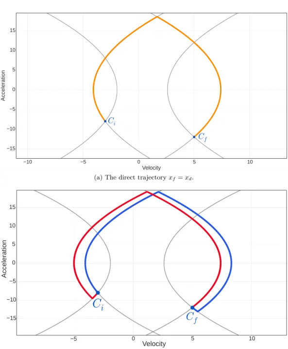
2.4 A direct trajectory. . . 49
2.5 Extension of the direct trajectory. . . 50
2.6 Negative extension of the direct trajectory. . . 50
2.7 Plot of optimal solutions time vs the length of the motion. . . 51
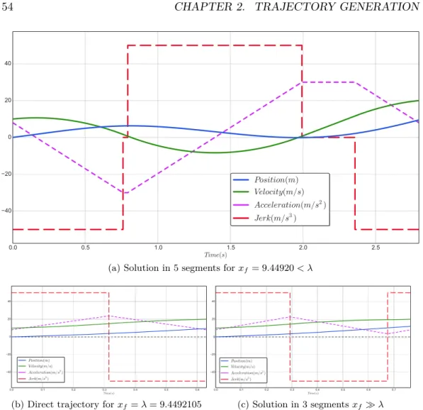
2.8 Introduction of discontinuities in the time-optimal function. . . 53
2.9 Effect of the discontinuities in the time-optimal function on the shape of the trajectory. . . 54
2.10 Shortcut trajectories introduce discontinuities in the time-optimal curve. . . 55
2.11 Discontinuities are reflected in the phase diagram with shortcut tra-jectories. . . 56
2.12 Discontinuities are reflected in the phase diagram with shortcut tra-jectories. . . 57
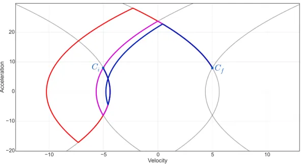
2.13 Illustration of the existence of five optimal solutions for a certain length of motion. . . 58
2.14 Use of symmetries on the shape of the trajectory to simplify the problem. . . 62
2.15 Illustration of a situation where the algorithm can fail. . . 64
3.1 An architecture for Reactive Trajectory Control. . . 72
3.2 The extended phase diagram. . . 75
3.3 Example of trajectories for each zone of the extended phase diagram. 76 3.4 A compromise between a trajectory duration and the time to reach the admissible domain. . . 77
3.5 An optimization of the extended phase diagram. . . 80
3.6 Comparaison of trajectories in the extended phase diagram and its in optimized version. . . 84
3.7 Comparaison of trajectories in the extended phase diagram and its in optimized version. . . 85
3.8 Comparison of our method with similar works. . . 86
3.9 A functional layer architecture for Reactive Trajectory Control. . . . 89
3.10 Single Dimensional Kalman Filter to estimate the robot’s kinematics. 91 3.11 Illustration of the control strategy to smooth the junction between two trajectories. . . 92
3.12 A KuKa LWR4 robotic arm used for our experiments. . . 95
3.13 The different vision systems used during our experiments. . . 96
3.14 Illustration of motion constraints abrupt switch on a KUKA-LWR4 joint axis. . . 97
3.15 Illustration of motion constraints abrupt switch on a KUKA-LWR4 joint axis. . . 98
3.16 Illustration of motion constraints abrupt switch on a KUKA-LWR4 joint axis and its depiction in the phase diagram. . . 99
3.17 Illustration of motion constraints abrupt switch on a KUKA-LWR4 joint axis and its depiction in the phase diagram. . . 100
3.18 Illustration of an experiment in an HRI context that validates the previous work. . . 101
3.19 Setup of a visual servoing experiment. . . 102
3.20 Plots of the angular trajectories during the experiment. . . 103
3.21 Plots of the angular trajectories during the experiment. . . 104
3.22 Plots of the angular trajectories during the experiment. . . 105
4.1 Screenshot of the IHM used by the partipicants of our study. . . 111
4.2 Picture of the experimental setup for the study. . . 112
4.3 Choice of the favourite imposed test. . . 116
4.4 Cross tabulation showing the subjects favourite motions. . . 117
4.5 Paramaters classified according to their impact on the subjects. . . . 117
4.6 Jido, a mobile robotic platform of LAAS-CNRS. . . 120
4.7 A simplified version of the Jido’s software architecture. . . 121
4.8 Description of frames used for the opening of a door. . . 123
C.1 Histograms depicting the values chosen by the subjects for their favourite motion. . . 136
C.3 Reasons motivating the choice of the favourite motion. . . 138 D.1 Illustration of the different frames for the localization process. . . 140 D.2 Figure summarizing the localization process of the door opening
2.1 A classification of the main trajectory planning algorithms in HRI context. . . 42 2.2 Comparison of the computational times according to the length of
the motion. . . 63 3.1 Illustration of the benefits of our algorithm for the time-optimality
of the trajectory. . . 81 3.2 Computation times. . . 86 3.3 Experiment settings. . . 102
[video-1] Online Trajectory Generation: Reactive Control With Return Inside an Admissible Kinematic Domain. https://youtu.be/7L-y168fg9g. (cited on pages 95 and 101).
[video-2] Reactive Trajectory Control: Online Trajectory Switching. https://youtu.be/0fuZNY1N5Q8. (cited on pages 98 and 102). [video-3] Fully Autonomous Door Opening at LAAS-CNRS. https://youtu.be/_mOtfrssyuY. (cited on page 119).
Contents 0.1 Context . . . . 7 0.2 Contributions . . . . 8 0.3 Publications . . . . 9 0.4 Manuscript organization . . . . 9
0.1
Context
The first robot was invented in the 1950s by George Devol who founded together with Joseph Engelberger the world’s first robot manufacturing company, Unimation. This robot, called Unimate, was sold to General Motors and replaced workers in dangerous tasks (Fig. 1).
It was in the 70s when the interest for robotics really emerged. It was barely half a century ago, and since then robots have been replacing humans in the industry. They are mainly use in tasks that are repetitive or considered too dangerous for humans. Robotics significantly increased the production capacities of industries while significantly reduced the costs related to human workers. The widespread use of industrial robots in the manufacturing world marked the beginning of an era of industrial automation. In 2015, more than 1.64 million industrial robots were in operation worldwide according to International Federation of Robotics (IFR).
However, this era of industrial automation is recently undergoing changes. In the industry of the past decades robots were confined in cages with prohibited access to humans. These robots were not capable of dealing with the safety risks related to the human presence. With the recent advances made in the field of Artificial Intelligence (AI), sensors, computer sciences and more, the collaboration between humans and robots is becoming possible. The close cooperation of humans and machines is motivated by the increased need for flexibility, adaptability and reusability of assembly systems. The main motivation being to get the best of both worlds, which is allowing humans and robots to combine their respective strengths. Industry is not the only domain that benefits from the growth of robotics. Another kind of robots called social robots is making its appearance.
In both cases these robots will have to adapt to human presence. They will have to ensure the physical safety of humans but also their psychological safety by providing interactions with sufficient ergonomics.
In the context of this thesis, whose main objective is Online Trajectory Gen-eration (OTG) for Human-Robot Interactions (HRI), we will have to find models of motion that satisfy the needs for efficient and flexible robots while ensuring the physical and psychological safety of humans.
Figure 1: Unimate, the grandfather of industrial robots.
0.2
Contributions
The work presented in this manuscript is focused on trajectory generation, mainly for Human-Robot Interactions.
The main contribution of this thesis is the extension of the softMotion library, a library for trajectory generation. The algorithm behind this library builds smooth cubic polynomial trajectories adapted for the context of Human-Robot Interactions. To our knowledge, it is the first complete algorithm that satisfies simultaneously all the following criteria to generate safe, efficient, adaptable and human-friendly motions:
• Real-time capable.
• General initial and end conditions for both velocity and acceleration. • General bounded jerk, acceleration and velocity.
• Asymmetric bounds. • Time optimal.
A second contribution is the extension of the previous algorithm to cope with non-admissible initial configurations, opening the way to trajectory generation un-der non-constant motion constraints. This feature is essential in the context of physical Human-Robot Interactions, as the robot must adapt its behavior in real time to preserve both the physical and psychological safety of humans. We have
also developed an architecture for robot control, based on reactive trajectory con-trol, which has been designed and demonstrated for real-world applications. Finally we investigated the role of kinematics in the definition of ergonomics properties of motions. This work is intended to determine the input parameters of the previous controllers in order to take into account the ergonomic constraints associated to the human’s presence.
This thesis was an opportunity for us to validate our software within a research contract in collaboration with the Safran group. The door opening demonstration presented in chapter 4 reproduces elements of this project.
0.3
Publications
Some of the contributions of this thesis have been published in a journal and in an international conference:
• Kevin Desormeaux, Daniel Sidobre. Online Trajectory Generation: Reactive Control With Return Inside an Admissible Kinematic Domain. IEEE/RSJ International Conference on Intelligent Robots and Systems (IROS), Macau, China, 4-8 nov. 2019. (Accepted)
• Daniel Sidobre, Kevin Desormeaux. Smooth Cubic Polynomial Trajectories for Human-Robot Interactions. Journal of Intelligent & Robotic Systems, vol. 95, no. 3, pages 851–869, September 2019. https://doi.org/10.1007/s10846-018-0936-z.
Other publications:
• Kevin Desormeaux, Daniel Sidobre. Smooth Cubic Polynomial Trajectories for Human-Robot Interactions. Journée des Jeunes Chercheurs en Robotique (JJCR), 07 november 2017.
• Kevin Desormeaux, Daniel Sidobre. Modèles temporels du mouvement et des forces d’interaction pour la manipulation interactive avec un robot. Con-grès des doctorants EDSYS 2017.
0.4
Manuscript organization
The manuscript outline is detailed hereafter:
Chapter 1 presents an analysis on the context of tomorrow’s robotics. We reuse this state of the art to replace our work on trajectory generation inside this context.
Chapter 2 introduces a complete mono-dimensional trajectory generation algo-rithm that build trajectories from arbitrary initial and final conditions, subject to general asymmetric bounds on jerk, acceleration and velocity. We identify and ad-dress the problem the time-optimal curve regarding the length of the motion, which can be non-linear and exhibit discontinuities. The extension of this algorithm to the multi-dimensional case is presented at the end of the chapter.
Chapter 3 completes the algorithm presented in the previous chapter so that it can cope with inadmissible initial configurations. This extension opens the way towards trajectory generation with non-constant motion constraints, an essential feature for physical Human-Robot Interactions. In a second part we present how to build an efficient control architecture as well as a strategy for Reactive Trajectory Control. The chapter is concluded by experimental results.
Chapter 4 introduces briefly some experimental work, notably a user study which purpose is to investigate the impact of kinematics on the ergonomic properties of motion. This work aims towards better Human-Robot Interactions and is in adequacy with the research presented in the previous chapters.
Chapter 5 concludes the work accomplished during this thesis, and opens some perspectives.
State of the art in motion
generation
Contents 1.1 Context . . . . 11 1.1.1 What’s a robot? . . . 11 1.1.2 State of Robotic . . . 131.1.3 Towards the future of Industry . . . 13
1.2 Human-Robot Interaction . . . . 16
1.2.1 Motivations . . . 16
1.2.2 Cobots . . . 19
1.2.3 Safety during Human-Robot Interaction . . . 21
1.2.4 Interaction Ergonomics . . . 25
1.3 Motion generation for Human-Robot Interaction . . . . 29
1.3.1 Architecture for autonomous robots . . . 29
1.3.2 Motion of a body . . . 29
1.3.3 Trajectory Generation for Human-Robot Interaction . . . 33
1.4 Conclusion . . . . 38
1.1
Context
1.1.1 What’s a robot?
So what’s a robot? Even if the answer might appears obvious, it is not. Robots are very diverse in regards to size, capacities, and design. There is no definition on which there is consensus, and there are still debates among the robotic community. So first lets take a general definition that is widely accepted: "A robot is an autonomous machine capable of sensing its environment, carrying out computations to make decisions, and performing actions in the real world1."
Now using this definition it is easy to find out why it is still subject to debate. When a person is asked to think of a robot, chances are she remembers the last viral YouTube video of the latest Boston Dynamic robot, such as Atlas (Fig. 1.1b).
1
(a) The famous Nao robot of SoftBank Robotics.
(b) Atlas of Boston Dynam-ics.
(c) A robotic arm of Univer-sal.
Figure 1.1: Examples of popular robots. Nao is one of the most sold robot world-wide. Atlas is famous for being one of the most advanced humanoid robot. Universal is a recognized brand producing robotic arms.
Or maybe an industrial assembly line with many robotic arms. It is also true that our representation of a robot is largely influenced by science fiction. Now if you ask this person if a smoke detector can be considered as a robot, she will probably laugh, and this question might appear absurd to the majority. However a smoke detector is a robot if we use the previous definition. It can sense the presence of smoke and produces an alarm alerting humans in the vicinity. If it is acceptable to label a smoke detector, a rice-cooker, or a thermostat as simple robots this idea is disturbing. When asked to define a robot, robotics pioneer Joseph Engelberger once said, “I don’t know how to define one, but I know one when I see one!”.
What a Humanoid legged robot, a robotic arm or an autonomous vacuum have in common that differentiates them from a dishwasher, or a thermostat? It can be the level of sophistication. However this could be difficult to evaluate. A more visible marker is the ability to affect the world by moving in it or by manipulat-ing thmanipulat-ings. Acceptmanipulat-ing this, we propose an updated definition: "A robot is an au-tonomous machine capable of sensing its environment, carrying out computations to make decisions, and performing actions altering the real world by producing motions." This definition is in line with the one proposed by the International Stan-dard of Organization, which defines a robot as a reprogrammable, multifunctional manipulator designed to move material, parts, tools or specialized devices through variable programmed motions for performance of a variety of tasks.
This definition introduces the subject of this thesis: motion generation for robots. More precisely we are interested in motion generation for robots capable of interacting with humans. In the continuation of this state of the art, we explore the state of robotics, the expectations towards the future generation of robots and
the issues related to HRI. Finally we will see how the field of motion generation can contribute to the emergence of more sophisticated generations of robots, suitable for Human-Robot Interactions.
1.1.2 State of Robotic
Robotics is an amalgamation of several disciplines, from mathematics and com-puter science to electronics, comcom-puter vision, sensors and many more. As a result, its evolution depends on the progresses made in each of these disciplines. The constant developments made in those fields lead to the emergence of new genera-tions of robots that are always more sophisticated. Robots are becoming cheaper, more efficient, robust, flexible and easy to use. From an era of heavy intimidating automatic machines, we are shifting towards safer and more friendly mechatronic systems. Robotics is no longer part of a distant future, and robots such as the educational Cozmo (Fig. 1.2e), or dust cleaners (Fig. 1.2b) are already popular (Fig. 1.2). Industrial automation is nothing new. The farming community already benefits from the addition of robots. Advanced robots are used to complete tasks which otherwise would put Humans lives at risk such as exploration in hostile envi-ronments. Nevertheless we are not yet able to see advanced robots in our everyday life, and the possibilities to interact with such robots are limited. The reality is that there remain huge challenges ahead for robotics, and practical home robots are still many years away.
So the question is : what are the difficulties restraining the development of robotics? It is nothing new actually. Robotics components are still costly. Robotics is still in its early days, and its arrival raises questions. Some are legitimate, such as the fear of job destruction. There are also the ethical questions behind the use made of these advances in robotics. Will we see one day killer robots? Fact is that society is not yet fully prepared to accept the major changes coming with the robotic revolution, but acceptance is on the way.
However these are not the only reasons slowing down the growth of robotics. A more practical reason that kept robots limited to factories and research labs remains today : it is the addition of the Human presence. This addition can simply be the result of humans and robots evolving in common places. Sometimes it will be the need for humans and robots to collaborate.
1.1.3 Towards the future of Industry
Two decades ago, the idea was suggested that the sequence of technological revolu-tions was not over, leading to a new universal technological revolution. The Second Machine Age is a term adopted by [Brynjolfsson 2014]. However the more popular term of Industry 4.0 was adopted after Germany began promoting its industrial development plan. The phrase fourth industrial revolution was first introduced by [Schwab 2016] at the 2015 World Economic Forum. In 2019, at the World Economic Forum meeting in Davos, Japan promoted another round of advancements called
(a) Aerospace (b) Consumer (c) Disaster Response (d) Drones
(e) Education (f) Entertainment (g) Exoskeletons (h) Humanoids
(i) Industrial (j) Medical (k) Military (l) Research
(m) Autonomous cars (n) Telepresence (o) Underwater
(a) Evolution of the industry.
(b) Components of the Industry 4.0.
Society 5.0.
So it is admitted that we are on the verge of a new industrial era, shifting from the third one to a fourth one (see Fig. 1.3a). In this new era, industries are often referred as smart factories. Machines are augmented with web connectivity and monitored by a system that can visualize the entire production chain and make decisions on its own. The trend is towards automation and data exchange in manufacturing technologies.
Some emerging fields are robotics, artificial intelligence (AI), nanotechnol-ogy, quantum computing, biotechnolnanotechnol-ogy, the (Industrial) Internet of Things, fifth-generation wireless technologies (5G), additive manufacturing, fully autonomous vehicles and more (Fig. 1.3b). Thanks to its multidisciplinary aspect, robotics will benefit from emerging technologies it is sure that robotics will be a major compo-nent of that industrial revolution. Now these are the questions we have to answer: What is expected from those future generations of robots? What will be their role? What are the scientific challenges to be addressed?
1.2
Human-Robot Interaction
1.2.1 Motivations
1.2.1.1 Robotics in Smart Factories
In the industry of the last decades or Industry 3.0 (Fig. 1.3a), and still to this day, industrial robots are usually confined in cages with prohibited access to Humans (Fig. 1.4). They accomplish repetitive tasks in a perfectly controlled environment. They cannot adapt to changes that would require an external intervention from a Human to reprogram them. Most of the time they are only composed of a robotic arm, and have a limited workspace. They are imposing, hard to manoeuvre, and not versatile. Reprogramming them requires expertise and is extremely time-consuming (Fig. 1.7). They are often used in assembly lines, and the car industry offer good examples of such environment (Fig. 1.4). These robots are vastly used in the indus-try because we can control their environment and remove or avoid most difficulties. This model for robots becomes obsolete as soon as the environment cannot be con-trolled. In the IEEE classification of robots, figuring fifteen categories (Fig. 1.2), the latter industrial model is obsolete in most of them. It is notably the case for the robotic of service and social robots due to the presence of Humans.
A trend of the industry of the future will be interconnected systems and au-tomation. Thanks to the progress made in AI, Industrial Internet of Things and many other, machines will be provided with more autonomy. At the same time, a second trend is making its appearance, that is Human-Robot Collaboration (HRC). The close cooperation of humans and machines in hybrid assembly is motivated by the increased need for flexibility, adaptability and reusability of assembly sys-tems. Future production systems will be characterized by individualized products under the conditions of a highly flexible mass production. Thus, new solutions for
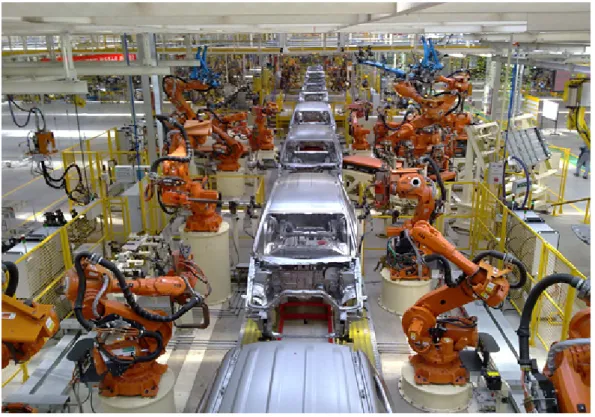
Figure 1.4: A typical assembly line composed of robotic arms confined in cages.
Figure 1.5: Human-Robot Cooperation combines the respective strength of the Human and the robot.
increased flexibility and inter-operability, such as flexible robotic equipment and intelligent decision making software platforms, must be investigated. To this end,
Figure 1.6: Comparison between classical industrial robots and future production assistants from [Bischoff ].
robots should be quickly and intuitively operated by humans, while guaranteeing a safe close interaction [Villani 2018].
In that regard, previous generations of robots will become obsolete in many situations. The industry of the future, often mentioned as industry 4.0, will see robots and humans cooperate in order to combine their respective strengths. The main reason behind the emergence of cobots is to get the best of both worlds (see Fig. 1.5). HRC allows to combine human’s cognitive abilities and adaptability with the accuracy, repeatability and strength of robots. In these new forms of cooperation robots are designated as cobots for collaborative or cooperative robots. Cobots are smaller, more flexible, and often cheaper to deploy. Focus is made on a easy to use aspect. With these qualities small and medium-sized enterprises should benefit from this new form of automation. The cobot market is expected to know a rapid growth. In a paper dedicated to the Kuka Light Weight Robot (LWR), [Bischoff ] offer a similar comparison between the classical industrial robots and the cobots (see Fig. 1.6).
In a study on safety for pHRI, [Bicchi 2008] reviews the advantages presented by such cooperation: "Humans have poor open-loop accuracy, tire easily, and are subject to repetitive stress injuries. In contrast robots have minimal sensing, not for lack of sensors but for their inability to interpret sensory input. However robots have high accuracy and speed and work indefinitely. Even with increasing sen-sorization, robots are not about to match a human’s literally millions of sensory receptors". Indeed tasks that are easy for us Humans, can be very challenging or
(a) A universal cobot used in car assembly production line.
(b) LBR iiwa of KUKA cooperating with BMW employee in Dingolfing’s factory.
Figure 1.7: Illustrations of cobots. The industry of the future?
yet impossible for automated systems. For example in [Russakovsky 2015], Humans inputs are used to extract information from pictures. [Michalos 2014] promotes a hybrid solution that combines the respective strengths of Humans and automated systems. The simulation experiments are promising, as they indicate significant savings in terms of productivity and operator’s working conditions. A survey on human-machine cooperation in assembly is proposed in [Krüger 2009]. The authors study the forms of cooperation between a human and a robot that can be used in assembly processes as well as the organizational and economical aspects. They de-scribe the advantages of combining the respective strengths of a human and a robot, and advocate in favour of these new kinds of cooperation, even compared to fully automated systems. These robots will have to be adaptable, flexible, and reusable. [Villani 2018] proposes an in depth review of industrial HRC. The authors offer a comparison between fully automated systems and hybrid human-robot solution. Challenges inherent to human-robot collaboration are addressed, such as safety and intuitive ways to program and interact with robots. In place of considering safety as a requirement that limits performance, they propose to inspect performance oriented solutions, meaning that performances should be optimized sub-ject to the constraint of safety. The paper reviews the different applications where collaborative robots have been used and sort out the advantages presented.
1.2.2 Cobots
The term of cobot was first introduced in [Colgate 1996]. A cobot is a robotic device, which manipulates objects in collaboration with a human operator. In its original definition a cobot’s task was to offer guidance to the human’s motion. This guidance was provided by using virtual surfaces to constrain the motion. To ensure safety the cobot did not provide motive power, which was given by the human. Since then its meaning has evolved to become a robot that physically interacts with Humans in a shared workspace and in a safe manner. They can also provide motive
Figure 1.8: Advantages of cobots illustrated by universal.
power. The latter definition includes a large panel of robots. From medical robots and exoskeletons, to social robots, through collaborative industrial robots that are able to work in cooperation with humans. However we will mainly focus on two types of cobots: industrial and social cobots.
1.2.2.1 Industrial Cobots
Industrial cobots have varying degrees of autonomy, diverse designs and can fulfil a wide variety of tasks.
We list here the main expectations towards a cobot: • Act safely,
• Pleasant to work with,
• Reduce effort and stress on Human operator, • Flexible,
As they have to share workspace with humans safety is the main requirement. Naturally a lot of works have been conducted in that regard (Sec.1.2.3). Their design is an example as they are smaller, lighter, and with rounded shape (Fig. 1.7a).
They mainly fulfil two objectives. The first one is to give more flexibility to in-dustries, and to compensate the weakness of fully automated systems by integrating humans in the loop (Sec.1.2.1.1). The second one is to reduce arduousness at work. To accomplish these objectives it is also necessary to make these cobots easy to use. They have to be easy to reprogram and that should be done by non-experts. They can be provided with more sophisticated interfaces (Fig. 1.8). This is also the subject of entire fields of robotics such as programming by demonstration ([Restrepo 2018]).
Another concern raised by the close cooperation between humans and robots is ergonomics (Sec.1.2.4). Often disregarded in favour of safety, or only considered for social robots (Sec.1.2.2.2), this aspect of the cooperation deserve more attention.
1.2.2.2 Social Robots
Often confused, service and social robots refer to two different types of robots. Again no official definition exists. The International Organization for Standardiza-tion (ISO) defines a service robot as a robot performing useful tasks for humans excluding industrial applications. These tasks are typically ungrateful and repeti-tive for humans. Vacuum robots like the Roomba (Fig. 1.2b) are a perfect example to illustrate this category.
Social robots are autonomous robots designed to interact and communicate with humans. Unlike service robots, social robots must behave according to social rules and behavior. This is a fairly new branch of robotics requiring a multidisciplinary approach by integrating the advances made in AI, psychology, neuroscience, hu-man factors and hu-many more. Unlike most robots, social robots are designed to be human-like. They have heads, eyes, screens that can take the form of touch pad to communicate with humans. They interact with people in a natural human-like manner in diverse applications such as education, entertainment, communication. Notable works on social works are [Breazeal 2003, Breazeal 2016, Fong 2003].
1.2.3 Safety during Human-Robot Interaction
As mentioned earlier, Human presence has been a restraining factor to the growth of robotics. With the apparition of the first cobot in 1996 finding solutions enabling Humans and robots to share common workspaces has been a major concern. It ap-pears that two main challenges have to be addressed: safety and ergonomics. Safety is the most obvious requirement and during the last years many advances have been made. Many studies on the matter have been published and the pro-gresses made in HRI safety partly come from technological propro-gresses made in control, vision, materials and many more.
Figure 1.9: Pepper, a well known social robot.
In the following we present the main safety standards as well as some literature on safety for human-robot interaction.
1.2.3.1 ISO standards
We give here a brief explanation of the main safety standards. A more in depth analysis can be found in [Villani 2018] (Fig. 1.10). The International Organiza-tion for StandardizaOrganiza-tion (ISO) proposes three standards which specify the security requirements for industrial robots : ISO-10218, ISO-15066, ISO-13482.
[ISO-10218-1 2011, ISO-10218-2 2011, ISO-15066 2016] applies to industrial robot systems, although the safety principles presented can be useful to other areas of robotics. [ISO-13482 2014] applies to personal care robots.
ISO-10218 is considered the central safety standard for industrial robots. It is composed of two parts: [ISO-10218-1 2011] describes the safety requirements for robot manufacturers. [ISO-10218-2 2011] contains safety requirements for the robotic integrator.
Figure 1.10: A classification of safety standards as provided in [Villani 2018]. The specifications of Type C category have priority.
ISO-15066 supplements the requirements and guidance on collaborative indus-trial robot operation given in ISO-10218. [ISO-15066 2016] idea is to allow contact between Humans and Robots, thus enabling them to share workspaces. If there were to be any incidental contact between human and machine, it shall not result in pain or injury. Thus ISO/TS 15066 provides guidelines for the design and im-plementation of a collaborative workspace that reduces risks to people. It specifies:
• Definitions,
• Important characteristics of safety control systems,
• Factors to be considered in the design of collaborative robot systems, • Built-in safety-related systems and their effective use,
• Guidance on implementing the following collaborative techniques: safety-rated monitored stop; hand guiding; speed and separation monitoring; power and force limiting.
This standard wants to be considered as a first step towards the development of pHRI and plans to evolute as applications are deployed and technology develops.
ISO-13482 specifies requirements and guidelines for the inherently safe design, protective measures, and information for use of personal care robots, in particular the following three types of personal care robots:
• mobile servant robot, • physical assistant robot, • person carrier robot.
[ISO-13482 2014] describes hazards associated with the use of these robots, and provides requirements to eliminate, or reduce, the risks associated with these haz-ards to an acceptable level. ISO-13482 covers human-robot physical contact appli-cations. The scope of ISO ISO-13482 is limited primarily to human care related hazards but, where appropriate, it includes domestic animals or property. Nev-ertheless this standard is limited. It doesn’t apply to earthbound robots, robots travelling faster than 20 km/h, robot toys, robots as medical devices and much more. Attention is drawn to the fact that for hazards related to impact (e.g. due to a collision) no exhaustive and internationally recognized data (e.g. pain or injury limits) exist at the time of publication (2014).
We have to keep in mind that these standards are yet very limited, and do not cover all scenarios. They evolute in reaction of robotics applications, thus are always behind and might not cover the latest applications or technologies.
1.2.3.2 Literature on HRI safety
A robot may not injure a human being or, through inaction, allow a human being to come to harm.
— Asimov, First law of robotics
Under no circumstances should a robot cause harm to people. Since safety is the main requirement to allow humans to evolve near robotic systems, there is already quantity of work on the matter. Numerous papers cover the theme of safety via the analysis of injury mechanisms. [Haddadin 2009] present an evaluation and classification of possible injuries during physical Human–Robot Interaction (pHRI). The impact’s velocity is demonstrated to be the dominant factor in the injury severity, since above a certain mass, potential injury would only depend on the impact’s velocity. A critic of the standard ISO10218 is made. For the authors the standard defines truly conservative safety requirements. Indeed the intention of the standard is to keep velocity very low, without compromise, and thus at the expense of efficiency. [Haddadin 2012] formulate the relation between robot mass, velocity, impact geometry and resulting injuries qualified in medical terms. The results are then used to generate motions with safe velocity bounds that explicitly consider the dynamic properties of the manipulator and human’s injuries.
The design of robots plays an important part in the making of safe interactions, and the Kuka LWR is a perfect example [Bischoff ]. This design implicates rather small and light-weight robots with rounded edges. These robots are equipped of torque sensors to detect collisions, and are capable of mechanical compliance. The design of intrinsically safe robots is studied in [Bicchi 2008]. It is noted that nature comes as a source of inspiration, for example the human arm. Humans can vary the compliance of their arm for different tasks, and even during different phases of a task. This variable compliance can be very useful in the making of safe and fast motions. The human arm is typically controlled to move slowly when it is stiff, and to be compliant while moving fast.
This example can directly be applied on some robotics systems. [Tonietti 2005] present a Variable Stiffness Actuator (VAC) along with a control approach. It allows controlling joint position and stiffness independently at the same time. The control approach consider stiffness similarly as a kinematic bound: by maximizing stiffness under a safe maximum stiffness bound. Hence accuracy is maximized under safety constraints. This illustrates how mechanical means and control strategies can be applied together to obtain safety-performance trade-off.
Not the least, safety comes mainly from planning, decision-making and reac-tive control. The works on collision detection/reaction and obstacle avoidance are numerous [Haddadin 2008, Kulić 2006, Kulić 2005, Kulić 2007].
Finally an in-depth study of methods for safe HRI can be found in [Lasota 2017]. This study also considers an important aspect of safety that is often neglected: psychological safety. It is in fact essential that the human perceives interaction with the robot as safe, and that interaction does not lead to any psychological discomfort or stress as a result of the robot’s motion, appearance, conduct or any other attribute. The interaction should not only assure physical safety, but also psychological safety through ergonomics properties.
1.2.4 Interaction Ergonomics
Stress at work is a major preoccupation for our societies and this phenomenon is not bound to a particular field. [Danna 1999, Ganster 2013] proposes multidisciplinary reviews on work stress and well-being at work. A review based on cost of work-related stress is presented in [Hassard 2018]. The cost of this social phenomenon is hard to estimate according to the authors. For [Rosch 2001], the health costs related to job stress is about $300 billion a year for American companies alone.
The origins of job related stress are multiple. In this work we are interested by the stress caused by robots. While safety remains the main criterion to enable humans and robots to share the same workspace, others emerge such as the level of stress and discomfort the human can feel in the vicinity of the robot. In this context, a robot should not cause excessive stress and discomfort to the human for extended periods of time. Some works have been conducted to evaluate the impact of cooperation with cobots on the mental safety of human’s beings. [Butler 2001] explores the interactions between humans and mobile personal robots. This paper
(a) (b)
Figure 1.11: Figure illustrating the notion of safety grid presented in [Sisbot 2007]. The robot takes into account that a human feels more threatened when he is sitting rather than standing.
describes the level of comfort the robot causes human subjects according to a variety of behaviors. These behaviors are defined by the robot’s speed, distance, design and more. In [Arai 2010], experiments are conducted to study the factors causing stress on a human operator working with a robot in a production assembly system. These factors can be the distance from a swinging robot to an operator, speed at robot’s movement towards an operator and so on. Similarly [Fujita 2010] studies the mental strains exerted by a robot hand over motion on a human operator.
In order to guarantee a certain level of comfort and safety for humans working near the robot, we can act mainly on two aspects of the interaction. The first aspect is based on the robot’s behavior and social considerations. The second one is based on the robot’s motion characteristics. A similar classification is made in [Lasota 2017]. In the following we present some of these works treating these two aspects of the interaction.
1.2.4.1 Behavioral ergonomics
The understanding of human social behavior constitutes an important field of study for roboticians. They attempt to extract the implicit rules and codes that define humans interactions in order to anthropomorphize a class of robots referred as so-cial robots (Sec.1.2.2.2). Such an approach can be used for the robot to anticipate Humans actions as a Human will be more efficient and more satisfied of the inter-action if the robot can anticipate his inter-actions [Hoffman 2007]. It can also be used for a robot to communicate its intents. A user will feel more comfortable knowing the goal of the robot early in its movements [Dragan 2013b, Dragan 2013a].
The study conducted in [Lasota 2015] shows that human-aware robots increase the level of safety and comfort of the participants, while increasing their perfor-mances. The authors demonstrate that maintaining physical safety by simply pre-venting collisions, as they are about to occur can lead to low levels of perceived
Figure 1.12: A depiction of several similar studies ([Abend 1982, Morasso 1981, Bizzi 1984, Flash 1985]). The formation of humans or monkeys arm motions un-constrained in the horizontal plane is investigated.
safety and comfort among humans.
[Sisbot 2007] presents a human aware motion planner to generate not only safe and effective paths, but also socially acceptable paths. The planner takes into ac-count humans by reasoning about their posture and field of vision. For example a human will feel more comfortable if the robot operate in its field of vision rather than in its back. Similarly a human will feels less threatened when standing in relation to when he is sitting (See Fig 1.11). An extension of this work is presented in [Sisbot 2010] that takes into account the task constraints as well as human kine-matics.
These work are usually integrated at a decision level. It is also possible to design more acceptable motions by looking at their properties.
1.2.4.2 Motion ergonomics
Human societal behavior is being studied and mimicked to provide robots with social skills. The same can be applied to human’s gesture and movement. In the first instance the resulting works are integrated at the highest layers of planning. The robot movement can be adapted to respect implicit social rules (Fig. 1.11).
But it makes sense only if the motion has been designed beforehand at a lower level to satisfy ergonomics properties.
Since we are used to velocity profiles and trajectories similar to our own by interacting with other individuals throughout our lives, it is reasonable to think we are going to feel more comfortable when interacting with a robot reproducing human-like movements. Thus, as for the behavioral ergonomics, the research of motions with good ergonomics properties will use the human model as a source of inspiration.
Among the works covering this field, the model described by [Hogan 1984] is very popular. Referred as minimum-jerk model, its intent is to be an organizing principle for a class of voluntary movements. It implements the result obtained in a previous study on primates where the objective was to find a general principle for motion control ([Hogan 1982]). At the same time similar studies (Fig. 1.12) were conducted on primates and humans [Abend 1982, Morasso 1981, Bizzi 1984]. It was found that humans generate roughly straight paths with single peaked bell shaped velocity profile for point-to-point motions. This generalization is mainly true if the movement is expressed in Cartesian space, or task space. It is less generalizable in joint space. According to the authors of [Hogan 1984], the previous observations suggest that the underlying goal behind these voluntary movements was to make the motion as smooth and graceful as possible. To verify this theory they used dynamic optimization with an objective function that minimizes the square of the jerk over the duration of the movement, since maximizing the smoothness implies minimizing the jerk. The model’s outputs were relatively close to the experimental results and it was assumed that the minimum-jerk model provides a good general description of voluntary arm movements. For [Hogan 1984], the main quality of this model is to be an organizing principle, hence it can be generalized to most voluntary motion and provides superior predictive capabilities. In [Flash 1985] this model is extended to cope with multi-axis. It must also be mentioned that despite the quality of these studies, there were conducted on little panels of subjects.
The minimum-jerk model was built around the hypothesis that the human be-havior could be derived from a single organizing principle, which provides a simple generalizable model. However with this assumption comes a trade-off that is a lack of flexibility and adaptability. Yet flexibility and adaptability are some of the most researched feature for future generations of robots (Sec. 1.2.2.1). The model was also simplified to assume symmetrical velocity and acceleration profiles. However the observed results showed that the acceleration phase of a point-to-point movement is often shorter than the deceleration phase [Abend 1982, Morasso 1981, Bizzi 1984]. Different works confirmed that velocity and acceleration curves are asymmetric for a large variety of motions [Beggs 1972, Ostry 1987, Nagasaki 1989], especially for skilled motions. [Flanagan 1990] demonstrates that human movements cannot be generalized by bell-shaped and symmetrical velocity profiles. Similar results are presented in [Shin 2015] showing that human-like movements cannot be reduced to bell-shaped velocity profiles, but depend on the characteristics and the purposes of given tasks. It is also known that the minimum-jerk model fail to achieve its
ob-jective of reproducing human-like motions for curved paths. [Huber 2009] proposes the "decoupled minimum-jerk" model in order to enhance the ergonomic properties of the original model.
To resume human-like motion tends to be smooth, thus with constrained jerk. It cannot be generalized and its characteristics depend on its purpose. Furthermore it is assumed that robots with human-like movements will be optimal for human-robot interactions. The majority of research works hence focus on mimicking humans. Yet the pertinence of robots with their own motion properties can still be investigated. In order to generate suitable motions for HRI a part of my work during this thesis was dedicated to the research of motions possessing satisfying ergonomic properties.
1.3
Motion generation for Human-Robot Interaction
1.3.1 Architecture for autonomous robots
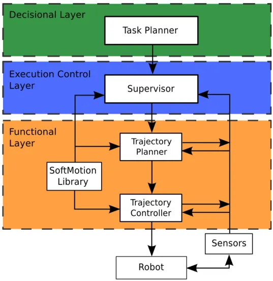
An autonomous robot architecture can be a very complex system. Its complexity and number of components is directly linked to the nature of the robot, and the complexity of the task itself. The figure 1.13 illustrates an architecture based on the works of [Alami 1998]. Three different layers are depicted: the decisional layer, the execution control layer, and the functional layer. The components placed inside these layers are related to our work that is mainly part of the functional layer. This architecture can be seen as a generic architecture for autonomous robots.
• The decision layer produces the task plan and supervises its execution. • The execution control layer that generally takes the role of the supervisor,
hence it controls the execution of the tasks emitted by the decisional layer, and the validity of those requests.
• The functional layer executes the tasks given by the above layers. This layer communicates with the robots to either send commands to the motors or to retrieve informations such as the axis angular positions. It can also re-trieves informations from other sensors that are needed for the task, treat those informations and then transmit them to the execution control layer in a understandable way. In the architecture that is specific to our work in this thesis, the functional layer is subdivided in two components: the trajectory planner and the trajectory controller. The role of each of these components is explained in more details in Sec.3.3.2.
1.3.2 Motion of a body
Kinematics is a branch of classical mechanics that describes the motion of bodies without considering the forces that cause them to move. It differs then from the field of kinetics or dynamics that is concerned with the relationship between motion
Figure 1.13: Our work in this thesis is mainly part of the functional layer.
and its causes, specifically, forces and torques. Simply put, kinematics describe the evolution of a body according to time by studying its position and its derivatives such as velocity and acceleration. During this thesis we focused our work on the study of kinematics.
1.3.2.1 Kinematics representation of a body
We first consider the localisation of a body B in a 3D space (See Fig. 1.14). The ref-erence frame FW is defined by an origin, OW, and an orthogonal basis (xW, yW, zW).
To B is associated the frame FB
To define the translation between two frames, three kinds of coordinates systems are commonly used:
• The Cartesian coordinates system • Spherical coordinates system
Figure 1.14: Rigid body localization in R3. • Cylindrical coordinate system
For the orientation several choices are available: • 3 angles (Euler angles or Bryant angles) • Rotation matrix
• Quaternion • Axis-angle
The homogeneous transformation matrix is often used to represent the trans-formation between two frames. The homogeneous transtrans-formation matrix between the frame FB and the frame FW is written like so:
T h[W,B]= R P 0 0 0 1 (1.1)
where R is a rotation matrix 3×3 and P a 3×1 matrix for the position of OB
expressed in FW. Given a point b which is localized in the frame FB by:
bB= [xb, yb, zb, 1]T
Figure 1.15: Differences between interpolation and approximation.
bW = T h[W,B]∗ bB
Now given a third frame FD associated to a body D, and given the transforma-tion T h[B,D] between FB and FD we obtain the transformation between FD and FW:
T h[W,D]= T h[W,B]∗ T h[B,D]
In this thesis various representations where used such as axis-angle, quaternion and transformation matrices. In this manuscript we will only use the last one. Readers can refer to [Siciliano 2016] for more details on the different representations and their relations.
1.3.2.2 Paths
A path between an initial configuration xiand a final configuration xf is a geometric
representation of a body movement that does not consider time. It can be defined in the configuration space (joint space), or in the task space (Cartesian space). In this thesis the task space is R3. Paths defined by a series of points define two types of problems: interpolation and approximation. Interpolation consists in generating a path that goes through all points. With approximation the path must be defined close to the points (See Fig. 1.15).
Notable works covering path planning are [Latombe 1990, LaValle 2006, Kavraki 2008].
1.3.2.3 Trajectories
Trajectories are continuous and derivable functions of time, defining the evolution of the position of the robot. They can be defined in task space or joint space. A trajectory can also be seen as the combination of a path with a law of temporal evolution.
Trajectories can be planned in joint space or Cartesian space. Trajectories planned in joint space present several advantages:
• They can be used directly to control actuators without need to compute in-verse kinematics.
• No need to deal with the redundant joints or singularities of multi-DOF ma-nipulators.
• The kinematic constraints can be considered while generating the trajectories. On the contrary, these constraints should be tested after inverse kinematics for Cartesian space trajectories
Trajectories can be classified in different categories. Figure 1.16 presents an example of classification. We can also differentiate online and offline trajectory generation. Online Trajectory Generation (OTG) regroups the solutions to gen-erate trajectories in real-time, typically under 1ms. In this manuscript we will not consider the multi-points type of trajectories, also called via-points trajecto-ries. The softMotion library already dispose of the faculty to generate via-points trajectories, either interpolated or approximated, after previous works presented in [Broquere 2010, Zhao 2014].
A summary of trajectory generation in an industrial context can be found in [Biagiotti 2008], while [Khalil 2004, Dombre 2007] offer the same for robotic ma-nipulators.
1.3.3 Trajectory Generation for Human-Robot Interaction 1.3.3.1 Objectives and requirements
The aim of this thesis is to improve Human-Robot Interactions by working on robots motions. More specifically this thesis is focused on trajectory generation and control.
Why trajectories? From the previous bibliography we can extract the key fea-tures the future generations of robots must present:
•
Efficiency (Sec.1.2.1).•
Adaptability and flexibility (Sec.1.2.1).•
Safety (Sec.1.2.3).Figure 1.16: A common classification among trajectories [Biagiotti 2008].
•
Ergonomics (Sec.1.2.4).Paths, which are pure geometric representation, have been the most widely used approach to describe movements. Paths are usually generated by a slow task planner, high in the architecture presented in Sec.1.3.1. Time consuming algorithms are used so they can be optimized and avoid obstacles. Hence they are planned offline and are used as inputs for a trajectory planner. Since the work we present is part of the functional layer (Fig. 1.13) we need efficient models with real-time capabilities. We also need to produce efficient motions, generally optimal in time, while considering the human safety and ergonomics properties.
Since paths do not possess a description of the time evolution they cannot be used in this context. Using trajectories instead of paths provides significant advantages [Sidobre 2012]:
• Not only the position can be planned and controlled, but also the velocity, the acceleration, the jerk and eventually higher derivative, allowing to define the smoothness properties.
• The travel time can be optimized taking into account kinematic constraints. • The movement is more precisely described allowing a better control.
From the state of the art we presented, and more precisely from Sec.1.2.3 and Sec.1.2.4, these properties are necessary to guarantee safe motions from a physical and psychological point of view, as well as efficient motions.
Nonetheless, the question of the choice of a trajectory model among the multiple models available is important to satisfy the requirements of future robots.
In order to produce efficient and safe motions, the model must be time-optimal under kinematic constraints that define safety, both physical and psychological.
This model have to be simple enough for real-time constraints that are linked to safety. It should also be capable to generate human-friendly movements to satisfy ergonomics constraints for a large variety of applications. Smooth trajectories ap-pear as excellent candidates since they possesses the advantages necessary to ensure safety, ergonomics, efficiency and adaptability required in the making of collabora-tive motions.
1.3.3.2 Smooth trajectories
Smooth trajectories were first introduced by [Hogan 1984], which was intro-duced in Sec.1.2.4.2. The first objective was to reduce wear on systems and improve path tracking [Craig 1986, Kyriakopoulos 1988]. These qualities make smooth trajectories particularly interesting for machining. For instance the study [Rivera-Guillen 2010] shows that tool-life can be improved up to 60%. One can resume the advantages of working with smooth trajectories as follow:
• Improve accuracy, thus moves can be executed more rapidly and accurately. • Extend the life span of the manipulators as vibrations are reduced thereby
preventing actuators to be damaged and reducing wear of the robot joints. • Reduce stress and discomfort of human co-worker.
Because of their qualities, smooth trajectories can be used in many contexts and can be employed in the making of more efficient and flexible robots. The smoothness of a trajectory can be defined by the number of derivative of the position and the extreme values of these derivatives. It is generally accepted that a smooth trajectory has at least continuous speed and acceleration, hence a bounded jerk. Considering a constant jerk during a period of time and its triple integral with respect to time, the obtained trajectory is defined by a cubic polynomial function of time. As these cubic functions are simple and their properties well known, they are easy to manipulate, and thus are widely used.
However higher order polynomials, especially quintics, are often used in the lit-erature to obtain smooth trajectories. The main reason being the need to compute trajectories with the possibility to specify position, velocity and acceleration at both ends, so that the robot is able to react quickly to unforeseen events, an imperative in HRI context to ensure safety [Kroger 2010]. One quintic is enough to compute a trajectory that meet these criteria, hence justifying their use [Craig 1986]. Un-fortunately, quintics generate more computational burden than cubics and their behavior between the way-points is more unpredictable and less faithful to the expected trajectory. This is explained by the tendency to oscillate of the quin-tics and generally higher order trajectories [Macfarlane 2003]. A solution is to use more than one quintic, but doing so they loose all interest, as simpler solutions exist. More recently, sequences of cubic polynomial functions have been used to define a smooth trajectory joining arbitrary positions, velocities and accelerations [Broquere 2010, Zhao 2014].
A well-known model of smooth trajectory is the minimum-jerk model. Minimum-jerk trajectories and smooth trajectories were actually introduced to-gether in the works of Hogan. This model was aimed to reproduce human motions to provide ergonomics properties. We discuss this model more in the following.
1.3.3.3 Minimum-jerk model
In order to generate suitable movements for a Human-Robot interaction, human motion appears naturally as a source of inspiration. Among the numerous works that have covered this field, the model described by [Hogan 1982] is very popular. This mathematical model describes the organization of a class of voluntary arm movements. We have introduced this model in details in Sec.1.2.4.2. This model present some flaws as it aims to provide an organizing principle for voluntary arm motions, while human movements cannot be generalized so easily.
Still minimum-jerk model has been popular and used in order to obtain co-ordinated and natural human-like motion. [Kyriakopoulos 1988] used a mini-max approach to minimize the mini-maximum jerk. This work was later extended by [Piazzi 1997, Piazzi 2000] where interval analysis is used to globally minimizes the absolute maximum value of the jerk along a trajectory. This global minimization avoids a flaw present in minimum-jerk works, generally subjects to get stuck in local minima. In [Amirabdollahian 2002], fifth order polynomials for minimum-jerk control are used with symmetric or asymmetric jerk bounds.
In most of the different approaches listed above kinematic constraints are not considered and the time has to be set a priori. Some studies have con-sidered minimizing a mixed criterion such as [Gasparetto 2008, Zanotto 2011]. [Gasparetto 2008] adopts a trade-off between a short execution time and smooth-ness of the motion by using a mixed criterion minimizing both the jerk and time. Kinematic constraints are taken as inputs, avoiding setting the time a priori.
This approach tries to overcome a major drawback of the model that is a lack of flexibility and efficiency. Another approach is the one proposed in [Villani 2018]. In place of considering safety as a requirement that limits performance, perfor-mance oriented solutions should be considered, meaning that perforperfor-mances should be optimized subject to the constraint of safety. In term of trajectory generation this means that we should look for the time-optimal trajectory under some kine-matic constraints that have been chose accordingly to the context. This approach satisfies all the requirements of efficiency, flexibility, and safety (physical and psy-chological). Our work in trajectory generation follows this approach that can be named constrained-jerk model.
1.3.3.4 Constrained-jerk model
In this approach, a suitable application dependent maximum jerk Jmax is
estab-lished through experiments or information provided by the manufacturer. This threshold is determined according to certain criteria related to the nature of the
task. Once the maximum jerk is defined the problem left is that of a classic time’s optimization. This is done by maximizing the jerk under the constraint J < Jmax. It provides time-optimal trajectories under task dependent constraints defined by the user. This approach can also be extended to acceleration, velocity and other derivatives. The main limitation of this model is that kinematic constraints must be specified by the user. However, unlike the previous ap-proach, it provides qualities that are essential to build the future generations of col-laborative robots that we expect to be efficient, adaptable and reusable (Sec.1.2.1). [Liu 2002] proposes a real-time algorithm to generate smooth trajectories from current velocity under constraints on jerk, acceleration and velocity. Optimal in most cases, this paper points the difficulty of managing non-null initials and fi-nals conditions. In the calculation steps for the maximum reachable speed, if the motion is too short to reach the maximum speed or acceleration, it becomes very difficult to compute an analytical solution online. A suboptimal strategy is then adopted by keeping the initial speed for a certain period. A similar approach is presented in [Haschke 2008] to generate third order time-optimal trajectories. The main contribution concerns the ability to handle arbitrary initial conditions, while end conditions must stay at rest. Nonetheless this work encounters numerical prob-lems and produces infinite jerk for short displacements. In that case, second order trajectories are employed as a fallback solution. Similar results can be found in [Kroger 2006], except it is for quadratic trajectories and hence not smooth, since the jerk is not bounded. [Kroger 2010] introduced a general Online Trajectory Gen-eration algorithm and an instance of it using third order polynomials. It brings a manipulator from an arbitrary initial state to an arbitrary final state except for the final acceleration, which is always null. This work as been extended in [Kroger 2012] such that time-variant kinematic motion constraints are considered.
Third order polynomial trajectories offer a simple solution to generate jerk bounded trajectories as they are easy to manipulate, keep the jerk bounded and can be generated online. They also avoid some major drawbacks of higher de-gree polynomials such as the tendency to oscillate, and are better for approxi-mation [Macfarlane 2003]. Moreover it has been demonstrated that a concatena-tion of at most seven cubic is enough to represent any time-optimal trajectory [Broquere 2008]. [Herrera-Aguilar 2006] proposes seven cubic equations to obtain Soft Motions for robot service applications. It was extended later in [Broquere 2008] to compute online time-optimal trajectories given any initial and final conditions, under bounded jerk, acceleration and velocity, for any number of independently act-ing axis. A solution for time-imposed trajectories is presented in [Broquere 2010] which leads to a simpler axis-synchronization for multi-axis systems. Yet, this so-lution had drawbacks, since it was not possible to both impose the time and keep the jerk bounded. An improvement was proposed in [Zhao 2014], which allows to have an imposed time and bounded jerk for sufficient large motions. For a point to point movement in an N-dimensional space, the time optimum straight-line motion is obtained by projecting the constraints on the line [Sidobre 2012].

![Figure 1.6: Comparison between classical industrial robots and future production assistants from [Bischoff ].](https://thumb-eu.123doks.com/thumbv2/123doknet/2225796.15443/26.892.224.642.166.544/figure-comparison-classical-industrial-robots-production-assistants-bischoff.webp)
![Figure 1.10: A classification of safety standards as provided in [Villani 2018]. The specifications of Type C category have priority.](https://thumb-eu.123doks.com/thumbv2/123doknet/2225796.15443/31.892.164.752.167.585/figure-classification-standards-provided-villani-specifications-category-priority.webp)
![Table 2.1: Classification of main trajectory planning algorithms in HRI context. The references are: [1]: [Liu 2002], [2]: [Macfarlane 2003], [3]: [Lambrechts 2005], [4]: [Kroger 2006], [5]: [Nguyen 2008], [6]: [Broquere 2008], [7]: [Haschke 2008], [8]: [Kroger 2010], [9]: [Ezair 2014], Ours: [Sidobre 2019]](https://thumb-eu.123doks.com/thumbv2/123doknet/2225796.15443/50.892.147.728.178.510/classification-trajectory-algorithms-references-macfarlane-lambrechts-broquere-haschke.webp)