Science Arts & Métiers (SAM)
is an open access repository that collects the work of Arts et Métiers Institute of Technology researchers and makes it freely available over the web where possible.
This is an author-deposited version published in: https://sam.ensam.eu Handle ID: .http://hdl.handle.net/10985/10236
To cite this version :
Walid NAJJAR, Cédric PUPIN, Xavier LEGRAND, Serge BOUDE, Damien SOULAT, Philippe DAL SANTO - Analysis of frictional behaviour of carbon dry woven reinforcement - Journal of Reinforced Plastics and Composites - Vol. 33, n°11, p.1037-1047 - 2014
Any correspondence concerning this service should be sent to the repository Administrator : [email protected]
Journal of Reinforced Plastics and Composites June 2014 vol. 33 no. 11 1037-1047
Analysis of frictional behaviour of carbon dry woven reinforcement
W. Najjar ab1, C. Pupin a, X. Legrand b, S. Boude a, D. Soulat b ,P. Dal Santo a
a. LAMPA, Arts et Métier ParisTech Angers, 2, Bd du Ronceray, 49035 Angers Cedex 01 b. GEMTEX, Ecole Nationale des Arts et Industries Textiles, Lille University North of France
Abstract:
During the preforming stage of woven reinforcement, in the first step of the RTM process, frictional phenomenon occurring at the tool/reinforcement interfaces and the reinforcement/reinforcement interfaces is one of the key parameters of the forming process. This behaviour must be correctly taken into account when modelling the process and a better understanding of the contact and friction phenomena occurring during the woven fabric preforming process is necessary for realistic simulation of the preforming process.
Although some existing studies concerning friction of reinforcement have been published, the complex frictional behaviour of fabrics is still not completely clear.
The experimental characterization of the frictional behaviour of a specific carbon woven reinforcement (G1151) used for aeronautical applications, is the aim of this paper, and three interfaces have been studied (G1151/G1151, G1151/Plexiglas, G1151/Aluminium). The Coulomb coefficients of friction occurring during contact between two layers of fabric and between the fabric and other materials have been determined. The effect of the variation of the normal pressure and the temperature on the frictional behaviour of this reinforcement has also been analysed. Comparisons between several frictional models, described in the literature, are also conducted, associated with these experimental results.
This study highlights a significant tribological anisotropy of the G1151 reinforcement and a dependence of the frictional characteristics on the applied pressure and the temperature
Keywords: Friction, Woven fabric, composite forming, Friction measurements
1 Corresponding authors Tel.: +33 2 41 20 73 35; fax: +332 41 20 73 20. E-mail addresses: [email protected], [email protected]
Introduction
In the aircraft industry, structural integrity (fatigue resistance, stiffness…) and weight saving are of primary importance. A possible way to achieve both of these goals is the use of composite materials with textile reinforcement as an alternative to metallic materials for structural components.
The manufacturing of composite parts requires the preforming of the textile structure. In the case of Resin Transfer Moulding, which is one of the most used manufacturing processes [1, 2], this step is performed on dry fabrics and is coupled to a resin impregnation phase, realized by injection or infusion. For thermoplastic composites, this performing step is performed at a temperature close to or higher than the melting temperature of the resin in order to make deformation of the textile prepreg possible [3]. The mechanical behaviour of textiles is a multi-scale problem. The macroscopic behavior depends on the interaction of yarns at the scale of the woven unit cell and at the level of the fibres constituting the yarns [4-6]. Associated with this multi-scale aspect, the textile reinforcement is subjected to large local and global deformations, during the preforming step, especially for complex shapes [7]. These complex deformations modify the fibre orientation, the fibre volume fraction, and can lead to defects such as wrinkles, buckles, or yarn misalignment [8-15]. For thermoset composites all these defects have a strong influence on the resin flow impregnation because they modify the pore space and geometry within the fabric and therefore the in-plane and through-the-thickness permeability components [16-19]. They consequently impact the performance of the composite part [20, 21]. To predict and control these defects, experimental analyse [10-13, 21-28] and numerical simulation models of the preforming step are simultaneously developed.
Numerical strategies are most commonly performed at the macroscopic scale using the finite element method [3, 6-7, 23, 26-36] which can take into account the mechanical behavior of fabrics (either dry or prepreg) and other process parameters, such as the blank-holder force, or specific punch shapes. Friction phenomena occur between the forming tools (i.e. punch, die and blankholder) and the fabric, and also between fabric layers for multilayered preforming. This phenomenon affects sliding of the reinforcement and has a consequent influence on the final shape of the preform (especially in the area between the blank-holder and die), on the punch load and on the deformation in the fabric. During thermoforming the presence of resin can also play the role of a lubrificant layer between the bodies involved in contact (tools-fabric or fabric-fabric).
It is therefore important to better understand and quantify this phenomenon to correctly take it into account for numerical modelling.
For the dry preforming step of single (or multilayer) fabrics the well-known Coulomb friction model is the most used for simulations. In this model the frictional force 𝐹𝑡 is considered to be proportional to an applied normal load, 𝐹𝑛, where the coefficient of proportionality is the friction coefficient 𝜇 [37] (eq.1)
𝐹𝑡= 𝜇𝐹𝑛 Eq (1)
A lot of numerical work existing in the literature uses this concept with a constant value for the coefficient of friction [10-11, 25-28, 35-36]. The chosen values for either tool-fabric or fabric-fabric interfaces are not generally justified. A recent numerical investigation showed that there is a significant effect of the choice of these values during the preforming stage of a plain woven fabric on the shear angle distribution and the evolution of the forming force [33]. A recent study used an anisotropic Coulomb law for the friction in NCF preforming simulations [38]. Several studies [36, 38, 40-43] have showed that the coefficient of friction varies with the applied normal load. Hence, Howell’s equation [39] can then be used (eq.2) instead of the Coulomb law:
Where 𝐾 is an experimentally determined proportionality constant and the exponent 𝑚 is a fitting parameter related to the deformation mechanism. In these studies, the influence of the relative positioning of the fabric and orientation of the yarns is not taken into account. However recent studies [44, 45] have shown an effect of these parameters on the frictional behavior.
It should also be noted that for thermoforming processes of composite structures the previous models can be replaced by lubricated friction models [3] described by the generalized Stribeck curves [43, 46-50], or by viscous models [41].
This paper concerns the experimental identification of the frictional behavior of a specific carbon fibre thin interlock (G1152). This reinforcement is presented in the following section of the paper. The second section describes the experimental apparatus used in this study, and presents the results in term of friction coefficient between this fabric and other material used during the preforming step. The influence of parameters such as the applied pressure and the temperature is then analyzed.
Presentation of the carbon reinforcement
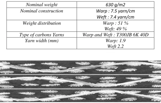
The G1151 woven fabric is a carbon thin interlock reinforcement (three yarn layers linked by the weaving) produced by Hexcel [51], the characteristics of this reinforcement are shown in table 1. The reinforcement is epoxy powdered on both sides (2.5% per side).
Table 1. Specifications of the reinforcement
Nominal weight 630 g/m2
Nominal construction Warp : 7.5 yarn/cm Weft : 7.4 yarn/cm Weight distribution Warp : 51 %
Weft: 49 %
Type of carbons Yarns Warp and Weft : T300JB 6K 40D
Yarn width (mm) Warp: 1.9
Weft 2.2
Fig.1: Three layers of the G1151 within warp yarn planes [52]
This reinforcement, often used for aeronautical applications, has been experimentally investigated in several studies. Tensile, in plane shear and bending characteristics have been published [53-57], its permeability [58] and its dry forming behaviour [7, 55, 56] have also been analyzed. The complex architecture has been also studied using tomographical analyse [52].
A few studies on the frictional behaviour of this fabric have been recently published [44] and report on the inter-laminar frictional phenomenon at the scale of the fabric taking into account the orientation of the yarns.
In this paper an experimental study is presented to characterize the static frictional behavior of this carbon fabric with several materials which can be used for tools during the preforming step. Associated to the definition given in literature [39] the term of static implies that the frictional behavior is studied regardless of the sliding. The fabric-fabric frictional behaviour will be also determined for multilayer analysis. The influence of parameters such as the applied pressure and temperature on the friction coefficient value is investigated. The originality of this study is that it involves the following material couples: aluminium / reinforcement (warp direction), aluminium / reinforcement (weft direction), Plexiglas / reinforcement (warp direction), Plexiglas / reinforcement (weft direction), reinforcement (warp direction)/ reinforcement (weft direction).
Experimental test bench developed for the frictional behavior analysis.
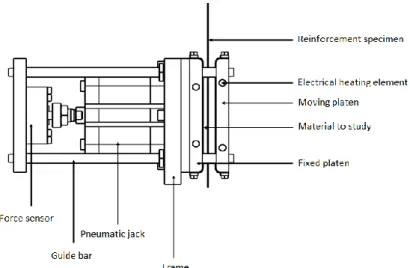
In order to undertake these tests, an experimental test bench has been developed (Figure 2) at the Arts et Metiers, LAMPA, Laboratory. The concept of this device is based on the classic principle of the contact area method consisting of two planar surfaces sliding against each other [45, 49]. To ensure a full plane/plane contact, a uniform normal force is applied. The advantage of this apparatus is that it allows tests to be carried out at elevated temperatures. In this case, the specimen and the plates are heated by conduction and not by infrared [40].
Fig 2 : Experimental test bench detailed scheme
The principal parts of the device are:
- A fixed and a moving plates which are both equipped with electrical heating components - A pneumatic actuator which applies the normal force.
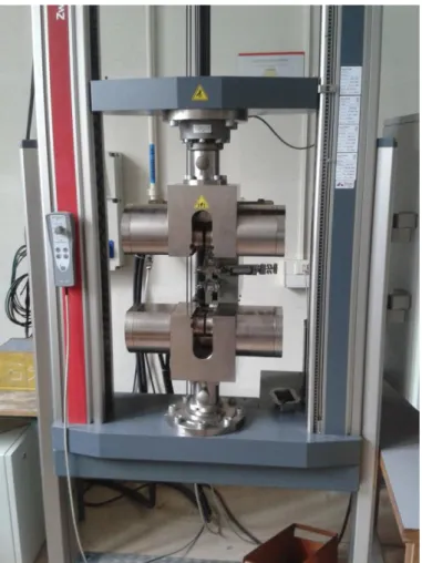
- A frame which allows the whole device to be integrated in a standard tensile testing machine. To perform the tests the device has been integrated in a Zwick tensile machine equipped with a 100 kN load cell (Figures 3-4)
Figure 3 : The tensile machine used
Figure 4 : Experimental test bench developed for friction tests integrated in the tensile machine
The fabric reinforcement specimen, of which the dimensions are indicated in figure 5, is attached to the mobile grip of the tensile machine via a clamping device. It is also sandwiched between the two plates which are coated with the second material of the friction couple to be tested (i.e. Plexiglas, aluminium or reinforcement). The contact area dimensions are 130mm×90 mm, where 130 mm is the plate length and 90mm is the specimen width. The used velocity was 1mm/s, and the total displacement distance was determined was 10 mm. Each performed test has been repeated 3 times and the average value is reported.
Figure 5 : G1151 reinforcement specimen used for the friction tests and the clamping device
In this section the classical Coulomb model is investigated. Using this model the tensile force on the specimen 𝐹𝑡 is considered to be proportional to the applied normal load 𝐹𝑛 (i.e. pressure force on the external plates). The coefficient of friction 𝜇 is then calculated as the ratio between 𝐹𝑡 and 𝐹𝑛 as presented in the following equation.
𝜇 = 𝐹𝑡
2𝐹𝑛 Eq(3)
Analysis of the frictional behaviour of fabric with different tool materials
Within the framework of this research and in order to analyse the reinforcement behavior during the preforming step, an experimental stamping machine (Figure 6) has been developed at the Gemtex laboratory [56, 59, 60]. The blank holder and opened die of this machine are made from Plexiglas (Figure 6) in order to observe the in-situ deformation, however the punch is made of aluminium. Consequently, the frictional behavior of the reinforcement is studied for these two materials.
(a)
(b)
Plexiglas-to-fabric friction
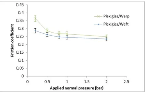
The first tests focused on the frictional behavior of the interface between Plexiglas and the reinforcement. The tests were performed at ambient temperature with different values of normal pressure in the range of [0.2 to 2] bar. The reinforcement was tested in its two main directions; the warp and the weft directions (Figure 8). Figure 7 shows the evolution of the coefficient of friction as a function of the applied normal pressure.
Figure 7 : evolution of the coefficient of friction versus pressure for the Plexiglas/Reinforcement couple
These curves show, in accordance with previous studies [62, 63], that the coefficient of friction decreases when the applied normal pressure increases. These curves also illustrate a difference between the coefficient of friction in the two different directions: warp and weft. Moreover, this frictional anisotropy is more significant for low pressures. The frictional anisotropy can be explained by figure 8 which shows the surface of the reinforcement. Indeed, although the reinforcement is materially quasi-balanced (approximately 7.4 yarns/cm for both directions), a difference in the weaving structure between the warp direction and the weft direction can clearly be observed. Indeed, the visible waviness in the weft is larger than in the warp. The length (x) of the visible waviness of the yarn constituting the weft is approximately twice that of the length of the visible waviness of the warp (0.46x).
Figure 8 : Surface of the G1151 reinforcement
The difference between the coefficient of friction in the warp direction and the weft direction can be then explained as follows: A yarn or a part of a yarn (a waviness for instance) in contact with an external body has greater resistance to relative motion, if this motion is not in its own direction. This effect is maximized when the motion is perpendicular to the yarn direction. For friction tests for the warp/Plexiglas combination, the motion is constrained by relatively long weft waviness. However, for a friction test with the weft / Plexiglas combination, the motion is constrained by the periodic warp waviness which is shorter. Moreover, this difference reduces when the pressure increases. Indeed, significant pressure decreases the crimp amplitude, the fabric surface becomes then topographically more flat and homogeneous [64] the frictional anisotropy mentioned previously becomes less pronounced.
Aluminium-to-fabric friction
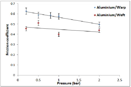
The second experimental study concerned the frictional behavior between the reinforcement and aluminium. Figure 9 reports the results of the friction tests at ambient temperature, for the material combination fabric/aluminium, for the two main directions (the warp and weft). The global trends observed in this figure confirm the results discussed in the previous section: (a) tribological anisotropy of the surface of the reinforcement (the coefficient in the direction of the warp is different from that in the direction of the weft), (b) the friction coefficient is inversely proportional to the pressure, (c) the difference between 𝜇𝑤𝑎𝑟𝑝 and 𝜇𝑤𝑒𝑓𝑡 is attenuated with a pressure rise. The analysis and explanations proposed in the previous section are also valid for this case.
Figure 9: Evolution of the coefficient of friction versus pressure for the couple Aluminium/Reinforcement
Moreover, it should be noted that the coefficients obtained in this case are significantly higher than those obtained using Plexiglas.
Fabric-to-fabric friction
In this section the tribological behaviour of a fabric/fabric interface is studied.
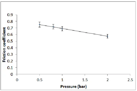
Depending on the orientation of the layers there are many possible configurations which can be investigated (warp/ weft, warp/warp, weft/ weft, weft /bias direction, warp /bias direction ...). In this study it has been chosen to analyse the frictional behaviour for a warp/weft combination which corresponds to a draping orientation of (0°/90°). Figure 10 shows the evolution of the coefficient of friction at ambient temperature as a function of the applied pressure for a fabric to fabric contact (warp/weft).
As observed in the previous cases, the coefficient of friction decreases proportionally with the applied pressure. It varies between 0.6 and 0.7 as shown in Figure 10. These values are within the range of those reported in recent studies [44], where the effect of several orientations on the friction coefficient has been studied, but for constant applied normal load. It should be noted, that in agreement with previous work [64] the fabric-to-fabric friction is higher than the fabric-to-metal one. This is due to the fact that two fabrics which are in contact may interact structurally; this contributes to a higher friction value compared to those obtained for contact with smoother surfaces.
Figure 10 : Evolution of the coefficient of friction at ambient temperature versus pressure for the material pair (Warp and Weft)
Investigation of the effect of temperature
Due to the presence of epoxy powder on the 2 sides of the reinforcement (described in Section 2), the frictional behavior is not the same at ambient and high temperature. Three temperature levels (20°C, 60°C and 120°C) are used to investigate the effect of temperature on the tribological behavior. Due to the sensitivity of Plexiglas to the temperature, this material is not included in these tests.
For elevated temperatures, the fabric layers were maintained between the heated platens for a period of time before starting the test to ensure a homogeneous temperature distribution within the specimen and the other material (either aluminium or reinforcement).
Fabric-to-fabric friction
A previous study [64], showed that the relationship between 𝐹𝑡 (contact tangential force) and 𝐹𝑛 (contact normal load) for a fabric/fabric friction case (polyester/cotton and polyester/viscose for instance) is better described using Howell’s equation (Eq.2).
For the present investigation this power law can be written as: 𝐹𝑡 𝐴 = 2𝐾 ( 𝐹𝑛 𝐴) 𝑚 Eq(4)
Where, 𝐴 is the contact surface, K is the friction parameter and 𝑚 is the friction exponent.
In order to verify the validity of this friction model, for a powdered G1151 reinforcement (warp/weft contact) at elevated temperature, and to investigate its applicability, it is compared to a linear model (Eq.5): 𝐹𝑡 𝐴 = 𝑎 + 2𝑏 𝐹𝑛 𝐴 Eq (5)
The results for the three different temperatures (20°C, 60°C and 120°C) and for both models are shown in figures 11, 12 and 13:
Figure 11:Fabric to fabric fiction (Warp/Weft 20°) Figure 12 : Fabric to fabric fiction (Warp/Weft 60°)
Figure 13 : Fabric to fabric fiction (Warp/Weft 120°)
The following table gives the coefficient of the power law and the linear models determined using a regression analysis (𝑅2) for each temperature.
Table 2. Model and regression coefficients
Power law fit Linear fit
K 𝑚 𝑅2 a b 𝑅2
T=20° 0.6295 1.261 0.994 -1.25e-02 0.44 0.979 T=60° 0.9625 1.458 0.992 -2.52E-02 0.50 0.961 T=120° 2.05 1.782 0.974 -8.57e-02 0.775 0.995
These figures and the associated table show that both models are globally able to describe the experimental results.
However, in conformity with [64], it seems that the power law model describes the frictional behaviour for low temperatures slightly better.
On the other hand, the linear model seems to better fit the experimental data for elevated temperatures. In the following, and in order to study the effect of the temperature on the tribology, the linear coulomb friction model (Eq 1) will be used.
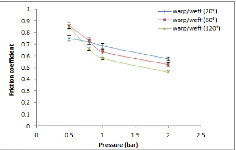
Figure 14 shows the evolution of the coefficient of friction, between one layer of the reinforcement in the warp direction and another one in the weft direction for three different temperatures.
It can be observed that the temperature and pressure effects are coupled. Except for at low pressure (0.5 bar) it can be seen that an increase in temperature induces the decrease of the coefficient of friction. In accordance with previous results, these curves show that the friction coefficient decreases when the normal pressure increases. It should be noted that these two phenomena have been already reported for thermoplastic reinforcement [43].
Figure 14 : Evolution of the coefficient of friction at different temperatures
This behavior can be explained by the effect of the epoxy powder and its viscosity decrease at higher temperatures. For low pressures and at ambient temperature (20 °C), the epoxy powder particles do not modify sliding between layers. For the same pressure (0.5 bar), a temperature rise from 60°C to 120°C, results in the polymerization of the powder particles which increases the roughness of the contact interface and creates a sticky surface. For higher pressures and temperatures (60 °C and 120 °C), the viscosity of the powder decreases. The epoxy acts as a lubricant which facilitates smooth relative motion between bodies in contact and reduced the frictional characteristics.
It is important to note that the friction coefficient presented in this study is the classical Coulomb friction coefficient. There is not dissociation between the local yarn contact phenomenon [44, 45] and the global apparent friction of the surface.
Aluminium-to-fabric friction
Figure 15 shows the evolution of the coefficient of friction as a function of the normal pressure for the aluminium/reinforcement material combination in the warp direction for the three temperatures mentioned previously. Even if a local discontinuity can be observed for the temperature of 120 °C and a pressure of 1 bar, where the friction coefficient slightly increases, the curves of figure 15 show essentially the same global evolution as in the previous section and the friction coefficient variation is more sensitive to the pressure at high temperature.
Figure 15: Evolution of the coefficient of friction versus the pressure for the Aluminium/Warp material combination for different temperatures
Conclusions
In this paper an experimental analysis of the tribology of the epoxy powdered G1151 reinforcement has been presented and is based on tests performed using a dedicated device developed at the LAMPA laboratory of Art et Métiers ParisTech. .
In continuity with certain investigation presented in the literature concerning this carbon reinforcement, this study gives additional experimental results on the frictional behaviour of G1151 with several materials which can be used as tools during the preforming stage. These results show a frictional anisotropy of this reinforcement due to the weaving architecture. This phenomenon has been also analyzed for fabric to fabric contact, using both a power law (Howell) and linear frictional model. This study also illustrates a dependence of the coefficient of friction on the pressure- temperature combination. Indeed, the interaction between these two parameters affects the the coefficient of friction due to the evolution of the contact conditions at the interfaces (fabric/fabric, fabric/tool). This work has been conducted at the scale of the reinforcement; future work will focus on the multi-scale behaviour of woven reinforcement especially at the scale of the yarns.
Acknowledgements
This work has been undertaken within the framework of the Défi composite project. The authors
would like to thank Oséo for its financial support, the project leader Airbus-France and other
partners (EADS IW and LoireTech) for the facilities provided.
References:
[1] Advani SG. Flow and rheology in polymeric composites manufacturing. Amsterdam: Elsevier; 1994. [2] Rudd CD, Long AC. Liquid molding technologies. Cambridge: Woodhead Pub. Lim; 1997.
[3] P. Wang, N. Hamila, P. Boisse. Thermoforming simualtion of multilayer composites with continuous fibres and thermoplastic matrix. Composites Part B: Engineering 2013 ;52: 127-136. [4 ]Boisse P, Gasser A, Hagege B, Billoet JL. Analysis of the mechanical behavior of woven fibrous material using virtual tests at the unit cell level. J Mater Sci 2005;40(22):5955–62.
[5] Lomov SV, Boisse P, Deluycker E, Morestin F, et al. Full-field strain measurements in textile deformability studies. Composites A 2008;39(8):1232–44.
[6] T. Gereke, O. Döbrich, M. Hübner, C. Cherif. Experimental and computational composite textile reinforcement forming: A review Composites: Part A (2013) 46 1–10.
[7] Allaoui S, Boisse P, Chatel S, N. Hamila, G. Hivet, D. Soulat, E. Vidal-Salle. Experimental and numerical analyses of textile reinforcement forming of a tetrahedral shape. Composites: Part A 2011;42(6):612–22.
[8]Potter K, Khan B, Wisnom M, Bell T, Stevens J. Variability, fibre waviness and misalignment in the determination of the properties of composite materials and structures. Composites: Part A 2008;39:1343–54.
[9]Bloom LD, Wang J, Potter KD. Damage progression and defect sensitivity: an experimental study of representative wrinkles in tension. Composites: Part B 2013;45:449–58.
[10] Lee J, Hong S, Yu W, Kang T. The effect of blank holder force on the stamp forming behavior of non-crimp fabric with a chain stitch. Compos Sci Technol 2007;67:357–66.
[11] Lin H, Wang L, Long AC, Clifford MJ, Harrison P. Predictive modelling for optimization of textile composite forming. Compos Sci Technol 2007;67:3242–52.
[12] Boisse P, Hamila N, Vidal-Sallé E, Dumont F. Simulation of wrinkling during textile composite reinforcement forming Influence of tensile, in-plane shear and bending stiffnesses. Compos Sci Technol 2011;71:683–92.
[13]P. Ouagne, D. Soulat, J. Moothoo, E. Capelle, S. Gueret. Complex shape forming of a flax woven fabric; analysis of the tow buckling and misalignment defect. Composites: Part A (2013);51;1–10 [14] Ouagne P, Soulat D, Hivet G, Allaoui S, Duriatti D. Analysis of defects during the preforming of a woven flax. Adv Compos Lett 2011;20:105–8.
[15] Prodromou AG, Chen J. On the relationship between shear angle and wrinkling of textile composite preforms. Composites: Part A 1997;28:491–503.
[16] Walther J, Simacek P, Advani SG. The effect of fabric and fiber tow shear on dual scale flow and fiber bundle saturation during liquid molding of textile composites. Int J Mater Form 2012;5:83–97. [17] Arbter R, Beraud JM, Binetruy C, Bizet L, Bréard J, Comas-Cardona S, et al. Experimental determination of the permeability of textiles: a benchmark exercise. Composites Part A 2011;42:1157– 68.
[18] Hou Y, Comas-Cardona S, Binetruy C, Drapier S. Gas transport in fibrous media: application to in-plane permeability measurement using transient flow. J Compos Mater 2012. http://dx.doi.org/10.1177/0021998312455676.
[19] Ouagne P, Bréard J. Continuous transverse permeability of fibrous media. Composites: Part A 2010;41:22–8.
[20] Lee SH, Han JH, Kim SY, Youn JR, Song YS. Compression and relaxation behavior of dry fiber preforms for resin transfer molding. J Compos Mater 2010;44:1801–20.
[21] Skordos AA, Aceves CM, Sutcliffe MPF. A simplified rate dependent model of forming and wrinkling of pre-impregnated woven composites. Composites: Part A 2007;38:1318–30.
[22] Dong L, Lekakou C, Bader MG. Processing of composites: Simulations of the draping of fabrics with updated material behaviour law. J Compos Mater 2001;35(2):138–63.
[23] Boisse P, Zouari B, Daniel J. Importance of in-plane shear rigidity in finite element analyses of woven fabric composite preforming. Composites: Part A 2006;37(12):2201–12.
[24] Li X, Bai S. Sheet forming of the multi-layered biaxial weft knitted fabric reinforcement. Part I: On hemispherical surfaces. Composites Part A 2009;40(6– 7):766–77.
[25]Vanclooster K, Lomov SV, Verpoest I. Experimental validation of forming simulations of fabric reinforced polymers using an unsymmetrical mould configuration. Composites Part A 2009;40(4):530– 9.
[26] Khan MA, Mabrouki T, Vidal-Sallé E, Boisse P. Numerical and experimental analyses of woven composite reinforcement forming using a hypoelastic behaviour. Application to the double dome benchmark. J Mater Process Technol 2010;210(2):378–88.
[27] Peng X, Rehman ZU. Textile composite double dome stamping simulation using a non-orthogonal constitutive model. Compos Sci Technol 2011;71(8):1075–81.
[28] S. Allaoui, G. Hivet, D. Soulat, A. Wendling, P. Ouagne, S. Chatel. Experimental preforming of highly double curved shapes with a case corner using an interlock reinforcement. International Journal of Material Forming. (accepted le 18/10/2012, under press). DOI: 10.1007/s12289-012-1116-5
[29] Hamila N, Boisse P. Simulations of textile composite reinforcement draping using a new semi-discrete three node finite element. Composites: Part B 2008;39:999–1010.
[30] Peng X, Rehman ZU. Textile composite double dome stamping simulation using a non-orthogonal constitutive model. Compos Sci Technol 2011;71:1075–81.
[31] Yu WR, Pourboghrat F, Chung K, Zampaloni M, Kang TJ. Non-orthogonal constitutive equation for woven fabric reinforced thermoplastic composites. Composites: Part A 2002;33:1095–105.
[32] Peng XQ, Cao J. A continuum mechanics-based non-orthogonal constitutive model for woven composite fabrics. Composites: Part A 2005;36:859–74.
[33] Peng X, Ding F. Validation of a non-orthogonal constitutive model for woven composite fabrics via hemispherical stamping simulation. Composites: Part A 2011;42:400–7.
[34] Charmetant A, Vidal-Sallé E, Boisse P. Hyperelastic modelling for mesoscopic analyses of composite reinforcements. Compos Sci Technol 2011;71:1623–31.
[35] R Tavana, S Shaikhzadeh Najar, M Tahaye Abadi, M Sedighi. Meso/macro-scale finite element model for forming process of woven fabric reinforcements. Journal of Composite Materials published online 20 July 2012; DOI: 10.1177/0021998312454034
[36] K. Vanclooster, S.V. Lomov , I. Verpoest. Simulation of multilayered composites forming. Int J Mater Form (2010) Vol. 3 Suppl 1:695– 698
[37] B. Cornelissen, B. Rietman, R. Akkerman. Frictional behaviour of high performance fibrous tows: Friction experiments. Composites: Part A (2013) ; 44 ;95–104.
[38] S. Bel, N. Hamila, P. Boisse, F. Dumont. Finite element model for NCF composite reinforcement preforming: Importance of inter-ply sliding. Composites: Part A (2012);43;2269–2277.
[39] Yuksekkaya ME. More about fibre friction and its measurements. Text Prog. 2009;41(3):141–93. [40] K. A. Fetfatsidis, J. A. Sherwood, J. Chen, D. Jauffres. Int J Mater Form (2009) Vol. 2 Suppl 1:165–168.
[41] K. Vanclooster, S. Van Goidsenhoven, S.V. Lomov , I. Verpoest. Optimizing the deepdrawing of multilayered woven fabric composites. Int J Mater Form (2009) Vol. 2 Suppl 1:153-156.
[42] WA Walbran, S Bickerton, PA Kelly. Evaluating the shear component of reinforcement compaction stress during liquid composite moulding processes. Journal of Composite Materials published online 3 May 2012. DOI: 10.1177/0021998312441811
[43] R.H.W. ten Thije, R. Akkerman, M. Ubbink, L. van der Meer. A lubrication approach to friction in thermoplastic composites forming processes. Composites: Part A 42 (2011) 950–960.
[44] Allaoui S, Hivet G, Wendling A, Ouagne P, Soulat D. Influence of the dry woven fabrics meso-structure on fabric/fabric contact behavior. J Compos Mater 2012;46 (6):627–39.
[45] Hivet G, Allaoui S, Cam BT, Ouagne P, Soulat D. Design and potentiality of an apparatus for measuring yarn/yarn and dry fabric/dry fabric friction. Exp Mech 2012, 52 (8): 1123-1136.
[46] J. L. Gorczyca-Cole, J. A. Sherwood, J. Chen. A friction model for thermostamping commingled glass–polypropylene woven fabrics. Composites: Part A 38 (2007) 393–406.
[47] J. L. Gorczyca, Sherwood J, Liu L, Chen J. Friction and shear in thermostamping of composites— Part I. J Compos Mater 2004;38(21):1911–30.
[48] L. Liu, J. Chen, J. L. Gorczyca, J.A. Sherwood .Modeling of Friction and Shear in Thermostamping of Composites – Part II. Journal of Composite Materials, Vol. 38, No. 21/2004
[49] K. A. Fetfatsidis, D. Jauffres, J. A. Sherwood, J. Chen, Characterization of the tool/fabric and fabric/fabric friction for woven-fabric composites during the thermostamping process. Int J Mater Form (2011) DOI 10.1007/s12289-011-1072-5.
[50] K. A. Fetfatsidis, L.M. Ganache, J.L. Goczyca, J. A. Sherwood, D. Jauffres, J. Chen. Design of an apparatus for measuring tool/fabric and fabric/ fabric friction of woven-fabric composites during the thermostamping process. Int J Mater Form (2011) DOI 10.1007/s12289-011-1058-3.
[51] Http://hexply.com/hexforce/database/web/front/main/index.php , accessed 21 june 2013.
[52] Badel P, Vidal-Salle E, Maire E, Boisse P. Simulation and tomography analysis of textile composite reinforcement deformation at the mesoscopic scale. Compos Sci Technol 2008;68(12):2433–40. [53] Lomov S, Boisse P, Deluycker E, Morestin F, Vanclooster K, Vandepitte D, et al. Full field strain measurements in textile deformability studies. Composites Part A 2008;39:1232–44.
[54] Launay J, Hivet G, Duong AV, Boisse P. Experimental analysis of the influence of tensions on in plane shear behaviour of woven composite reinforcements. Compos Sci Technol 2008;68(2):506–15. [55] Vu Duong Anh .Experimental study of the mechanical behaviour of woven fabric reinforcement during the preforming of non-developpable shapes. PhD Thesis, University of Orléans; France, 2008 [ in French]
[56] Najjar W.Contribution to the simulation of composite woven fabric reinforcements simulation. PhD Thesis, Art et Métiers Paristech CER Angers, France, 2012 [French]
[57] De Bilbao E, Soulat D, Hivet G, Gasser A. Experimental study of bending behaviour of reinforcements. Exp Mech 2010;50(3):333–51.
[58] Laine B, Boust F, Boisse P, Hivet G, Lomov SV, Fanget A. Perméabilité des renforts fibreux. Rev Compos Mater Avances 2005;15:385–400.(in French)
[59] Najjar W, Legrand X, Pupin C, DalSanto P and Boude S (2012). A simple discrete method for the simulation of the preforming of woven fabric reinforcement. Key Engineering Materials 2012;504-506; 213-218.
[60] W. Najjar, X. Legrand, P. Dalsanto, D. Soulat, S. Boude. Analysis of the blank holder force effect on the preforming process using a simple discrete approach. Key Engineering Materials 2013;554-557 441-446.
[62] Vanclooster K, Lomov SV and Verpoest I. Inter-ply and tool-ply friction measurement of woven reinforced thermoplastic composites at forming conditions. Proceeding TEXCOMP10, Lille,
France, 2010.
[63] Sachs U, Fetfatsidis KA, Schumacher J, Ziegmann G, Allaoui S, Hivet G, Vidal-Sallé E and Akkerman R (2012). A Friction-Test Benchmark with Twintex PP. Key Engineering Materials 2012 504-506 ; 307-312.
[64] Das A, Kothari AV and Vandana N. A study on frictional characteristics of woven fabrics. (2005) AUTEX Research Journal,2005; 5(3); 133-140