Science Arts & Métiers (SAM)
is an open access repository that collects the work of Arts et Métiers Institute of Technology researchers and makes it freely available over the web where possible.
This is an author-deposited version published in: https://sam.ensam.eu Handle ID: .http://hdl.handle.net/10985/6737
To cite this version :
Bassel ASLAN, Julien KORECKI, Thimoté VIGIER, Eric SEMAIL - Influence of Rotor Structure and Number of Phases on Torque and Flux Weakening Characteristics of V-shape Interior PM Electrical Machine - In: International Conference and Exhibition on Ecological Vehicles and Renewable Energies 2011., Monaco, 2011-03-31 - EV3 : Traction drives and generators - 2011
Any correspondence concerning this service should be sent to the repository Administrator : archiveouverte@ensam.eu
1
Influence of Rotor Structure and Number of Phases on Torque
and Flux Weakening Characteristics of V-shape Interior PM
Electrical Machine
Bassel Aslan, Julien Korecki, Thimoté Vigier, Eric Semail
École Nationale Supérieure d’Arts et Métiers, Boulevard LOUISXIV, LILLE, FRANCE
E-mail: bassel.aslan@yahoo.com
Copyright © 2011 MC2D & MITI
Abstract: This paper investigates the influence of the rotor structure on torque and Flux weakening
region of V-shape IPM machine from TOYOTA PRIUS type, more specifically, keeping always the same magnet volume, we study the effect of the open angle between the two magnet segments of each V-shape pole on the machine performance. Moreover, in order to examine the impact of phase number on the machine characteristics, PRIUS structure is transformed into 5-phase machine of the same type and dimensions. As well, an optimization procedure is carried out to determine the optimal open angle according to main characteristics. The previous investigation is done by using a free Finite Elements Methods (FEM) program coupled with another optimization program. Using this obtained methodology the study analyzes for 3-phase and 5-phase machine the average and pulsation of torque, cogging torque, phase back-EMF, constant power operating capability.
Keywords: V-shape magnet machine, straight-shape magnet machine, multi-phase machine, torque
ripples, flux weakening.
1. Introduction
Permanent magnet motor (PM) is one of the most attractive motors applied in compact electric propulsion system, due to its high efficiency, high reliability, and power density. The interior permanent magnet motor (IPM) adds a reluctant torque generated by rotor saliency to the original magnetic torque. Therefore this motor has higher torque density compared with surface mounted permanent magnet motors (SMPM). Also extended flux weakening region is one of the advantages of IPM motors, because of their reluctance effect and rigid rotor structure which permits to reach high speed [5].
On the other hand, the major drawback of IPM structure is high torque ripple because of the non-sinusoidal magnetic field distribution in the air gap, which implies harmonic components of the back-EMF, leading to torque ripple even in the case of sinusoidal current supply. As well, cogging and reluctance torque are other important sources of torque oscillation. The shape and configuration of permanent magnets in the
rotor is an essential factor to consider during IPM design, trying to create an optimum spatial flux linkage.
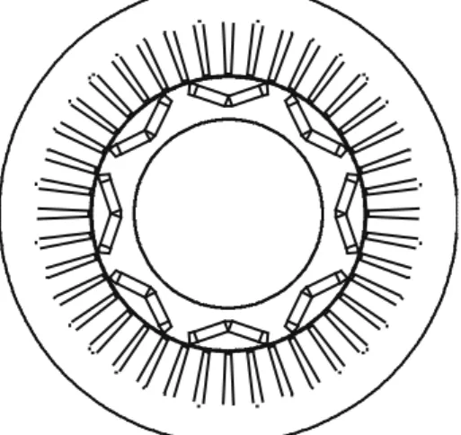
Nonlinear finite element program “femm” is used to study and optimize one of the rotor magnet configurations in V-shape electrical machine. The considered magnet configuration is the open angle of V-shape pole. The angle is optimized according to the machine general performances (average torque, torque ripple, flux weakening region). Later on in this paper we will refer to the pole open angle α with the value of h (the distance between the middle point of each magnet pole and the outer circumference of the rotor) see figure1.
This paper studies two machines which have the same type and dimensions of TOYOTA PRIUS machine [6], but they differ in the phase number (3 and 5). Comparisons are done to find out the optimum pole open angle in both machines, hopping to benefit from the advantages of 5-phase machine over the classic 3-phase structure: better fault tolerance, lower pulsating torque, splitting the power across more inverter legs, and lastly additional degrees of freedom can be used for
2 different purposes [8]. In order to have a fair comparison, the total volume of permanent magnets is kept constant in both machines.
Figure 1. Permanent magnet configurations.
2. Three-phase TOYOTA PRIUS type machine
A 3-phases, 8 poles, 48 slots IPM motor is considered in this study. This motor has a distribution winding with q=2 (number of slots per pole and per phase). The motor has the same structure and dimensions as the machine Prius THS II 2004 [6]. The rotor configuration is also the same type of V-shape magnets, but with different pole open angle. This paragraph studies and compares the variation of the machine performance with this angle (h value), including the original PRIUS value (h=10.96), Fig .2 presents a cross section of this machine. The motor is supplied with three sinusoidal shifted currents of amplitude 212 A. Average torque is the first to be studied, and different sources of torque oscillation are examined (cogging and reluctant torque), then torque-speed characteristic is determined (flux weakening region).
A. The average torque Taverage
Instead of searching the static torque [10], this paper uses FEM program “femm” to calculate the average torque of the machine according to the electrical angle ψe (Phase difference
between current and back-EMF), considering different values of the pole open angle, always without changing the volume neither the shape of magnets.
Figure 2. Cross section in 3-phase TOYOTA PRIUS type machine.
B. The average torque Taverage
Instead of searching the static torque [10], this paper uses FEM program “femm” to calculate the average torque of the machine according to the electrical angle ψe (Phase difference
between current and back-EMF), considering different values of the pole open angle, always without changing the volume neither the shape of magnets.
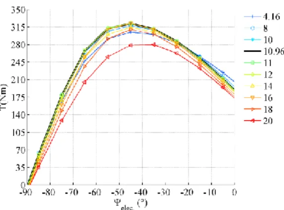
Fig. 3 shows the curves of average torques which correspond to different h values. It can be noted that curves of average torque do not vary so much with the value of h (magnet open angle). However it sappearsthat PRIUS structure with h=10.96 produces the highest torque among all the other configurations at ψe=-45
o
. This is due to the added reluctant torque which is likely more affected by the value of h than the electromagnetic one, simply because changing the magnet open angle h affects the paths of flux paths resulting in inductance variation (Ld, Lq).
Figure 3. Average torque versus electrical shift angle.
Fig.4 shows the no-load Back-EMF frequency spectrums for 10 different values of h,as it can be noted, no big difference in the amplitude of the first harmonic between examined
3 configurations, which proves that pole open angle does not have remarkable effects on the average electromagnetic torque.
Figure 4. No load Back-EMF frequency spectrums for h = [4.16mm ; 20mm]. C. The cogging torque
Torque oscillation is one of the important characteristic in traction application; therefore this paper investigates the effect of magnet open angle on the torque ripple. First of all, the cogging torque sensibility to h is studied using a methodology consisting in a coupling between an optimization program in Matlab and the FEM “femm”. This methodology helps to find the optimal magnet open angle hoptimum which
generates the minimum cogging torque [2]. The chosen criteria for this optimization is minimizing the RMS value of cogging torque, and the result is hoptimum = 11.515 mm, while
value of h in original PRIUS machine is h = 10.96 mm. Fig.5 shows the cogging torque for different magnet open angles.
Figure 5. Cogging torque for 3-phase PRIUS type machine
D. Torque ripples
To continue with torque oscillation phenomena, this paper studies the effect of pole open angle on the torque ripple while the machine is operating with different electrical angle ψe . In order to have comparable values,
relative amplitude of oscillation is considered ΔT/Taverage (ψe, h).
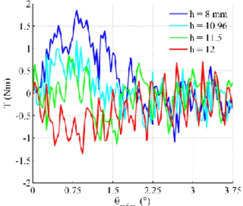
Fig. 6 shows the curves of relative torque oscillation, where each curve represents the torque oscillation of one configuration (h) according to the electrical angle ψe. If we
observe the curves close to ψe =0, we find that
the configuration with h=18mm has the lowest relative oscillation in torque (down to 8%). This result corresponds to the Back-EMF frequency spectrums (Fig 4) where the seventh harmonic which can disturb the torque (with the fifth one) is almost null in this configuration (h=18mm).
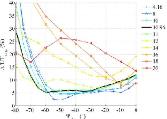
Nevertheless, as the motor must work in a wide range of torque, it can be considered that a more global comparison is necessary. So the average value of torque relative oscillation is calculated along the flux weakening region ψe [-80°,-45°]. Fig. 7 presents this average according to h, where it can be noted that the structure with h=8mm has the lowest average of torque relative oscillation (about 19%) all over the flux weakening region starting from maximum torque point at base speed (1200 rpm) up to the maximum speed of 7000 RPM (corresponding to ψe close to -80°).
Figure 6. Torque ripple in 3-phase PRIUS type machine (Ip = 212 A).
Figure 7. The average of relative torque ripples over the flux weakening region.
E. Magnetic flux density in the air gap
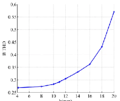
In this study also the THD (total harmonic distortion) of magnetic flux density is calculated for different configurations as an
4 alternative index of the iron loss reduction. The optimum h which minimizes the THD of the flux density distribution in the air gap is searched [7]. Fig. 8 shows the THD value for different pole open angle, and simply we can notice that straight-shape magnets structure with h=4.16mm has the lowest THD value.
Figure 8. THD of magnetic flux density in the air gap.
F. Flux weakening region
Power-speed and torque-speed characteristics and how flux weakening region is affected by the magnet open angle (h) are another important performances of the machine. First of all, Ld, Lq are calculated using FEM
software and in order to consider iron saturation this calculation is done for three different load currents (amplitude 212A, 150A, 99A). Figs. 9a and 9b present the calculated values of Ld, Lq according to the magnet open
angle. The value (Lq-Ld) which decides the
amount of added reluctant torque is also represented in Fig. 9c.
Figure 9. Ld and Lq calculated for 3-phase PRIUS
type machine.
The functionality region of the machine is limited by two main factors, maximum current due to thermal and magnetic constraints and maximum voltage imposed by the DC bus of the inverter [4] 2 max 2 2 2 max 2 2 2 max 2 2 )) ( ( ) ( V i L p i R i L p i R V v v I i i d d q s q q d s q d q d (1)
As we can see in the last two inequalities, the phase resistance RS, permanent magnet flux f,
and the two inductances Ld, Lq can directly
define the flux weakening capability and possible speed range.
The electromagnetic torque can be written as:
( . ( )) 2 3 q d q d f q i i L L i p C (2)
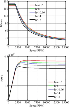
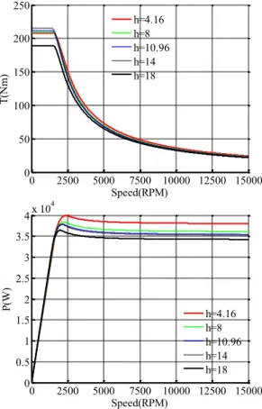
Of course the last calculation does not consider the inductance variation because of saturation, neither the iron loss in the machine. The machine PRIUS second generation THS II 2004 is supplied by an inverter working on 500 volt DC bus, and giving a maximum current amplitude of 230 A [10]. Considering those limits with the calculated parameters, and by applying a flux weakening strategy we can draw the curves torque-speed, and power-speed of the machine. Fig. 10shows the curves which present the torque/power-speed characteristics of the machine for 5 magnet configuration (5 values of h). Those curves are calculated depending on a strategy of flux weakening which minimizes the Joule losses at base speed, and then for each higher rotating speed it forces the machine to function with the maximum possible torque. Furthermore this strategy considers the reluctant torque while chasing the optimum point of functionality. It can be noted from figure 10 (power-speed) that all structures have a constant power operating capability, while the machine with straight-shape magnets (h=4.16 mm) has the best characteristics along the flux weakening region, due to the highest torque produced by this configuration up to reach high speeds. However the configurations PRIUS (h=10.96 mm) and (h=14 mm) are the best at basic speed region (before flux weakening) where they produce higher torque than the other structures.
In fact this result corresponds to the
inductances calculations (Ld, Lq) in figure 9
which shows that the structures close to PRIUS machine (h is close to 11 mm) benefit more from the reluctant effect than the others, owing to their
higher value Lq-Ld. Nevertheless this difference
5
can notice in figure 9 for a lower current of 99A. When low current is applied the reluctance
indication Lq-Ld varies much more with h than in
the case of higher currents, and that because the machine with lower currents is less saturated, and consequently the role of magnet structure (pole open angle) becomes more important.
0 2500 5000 7500 10000 12500 15000 0 50 100 150 200 250 300 Speed(RPM) T (N m ) h=4.16 h=8 h=10.96 h=14 h=18 0 2500 5000 7500 10000 12500 15000 0 1 2 3 4 5x 10 4 Speed(RPM) P( W ) h=4.16 h=8 h=10.96 h=14 h=18
Figure 10. Torque/Power – Speed characteristics for the 3-phase PRIUS type machine for Ip = 212A. Fig. 11 shows the torque-speed characteristics of the machine for the same five values of h but with lower current amplitude of 127A. Here we can easily classify the structure with (h=14) as the best choice at low speed application (more generated torque), while the straight-shape magnets structure stays the best choice for higher speeds along the flux weakening region owing to its high ratio: magnet flux / Ld. The author in [3] finds
similar results but with fractional slot winding machine.
In this study we keep always the same magnet volume, but it worth to mention that V-shape magnets allow installing bigger magnet segments which give more torque at low speed thanks to higher linkage, but in the same time bigger magnets lead to shorter flux weakening region due to the decrease in d-axis inductance [1]. 0 2500 5000 7500 10000 12500 15000 0 30 60 90 120 150 180 Speed(RPM) T (N m ) h=4.16 h=8 h=10.96 h=14 h=18 0 2500 5000 7500 10000 12500 15000 0 1.5 3 4.5x 10 4 Speed(RPM) P( W ) h=4.16 h=8 h=10.96 h=14 h=18
Figure 11. Torque/Power – Speed characteristic for the 3-phase PRIUS type machine for Ip = 127A.
3. Five-phase TOYOTA PRIUS machine type
The idea behind the comparison between PRIUS machine and a 5-phase machine is to examine the effects of the phase number on its performance, while keeping as possible the same rotor structure, dimensions, and winding type (integral slot winding). Therefore a little modification is done to allow PRIUS type machine to support 5-phase integral slot winding by reducing the slots number from 48 to 40, then as a result we get a winding of one slot per pole and per phase (q=1). Fig 12 presents a cross section of this machine. The motor is supplied with five sinusoidal shifted currents of amplitude 127A keeping the same linear current density as in the original PRIUS machine.
Like in the last paragraph, this one studies and compares the variation of the machine performance with the pole open angle (h value). The average torque is the first to be studied considering another degrees of freedom offered by this multiphase machine (other Back-EMF harmonics. Besides that, different sources of torque oscillation are examined (cogging torque, torque ripple), then torque-speed characteristic is determined (flux weakening region).
6 Figure 12. Cross section in 5-phase PRIUS type
machine.
A. Average torque T (considering the main back-EMF harmonic)
First of all the average torque of the machine supplied with five sinusoidal shifted currents is calculated using FEM program “femm”. Fig. 13 shows the curves of average torques which correspond to different h values. No big difference can be noted between this 5-phase machine and 3-phase PRIUS one. The curves of average torque do not vary so much with the value of h. However it appears that the machine with h=10.96 (PRIUS structure) produces also the highest torque among all the other configurations at ψe=-45
o
.
Fig. 14 shows the no-load Back-EMF frequency spectrums for 10 different values of h, where it can be seen that PRIUS structure (h=10.96) has a low main harmonic amplitude. This means that if the maximum average torque is obtained by PRIUS configuration in figure 13 it is due to its reluctant torque. Of course with this new winding, much more harmonic of electromotive force can be noticed. However it will be seen in next paragraph that these harmonics does not produce more torque pulsations in the 5-phase configuration.
Figure 13. Average torque for 5-phase PRIUS type machine.
Figure 14. No load Back-EMF frequency spectrums for h = [4.16mm ; 20mm]. B. Using another degree of freedom offered by the multiphase structure to decrease the current peak (considering the third Back-EMF harmonic)
A 5-phase machine can be divided into 2 two-phase fictitious machines which are mechanically coupled but magnetically independent. Moreover, each fictitious machine is characterized by a family of particular back-EMF harmonics, therefore the main fictitious machine is sensitive to the first current harmonic, while the other one (secondary machine) interacts mainly with the third current harmonic [11]. In a 5-phase machine the third, fifth and seven harmonics of back-EMF do not interact with the first harmonic of current.
Furthermore by observing the frequency spectrums of the back-EMF in figure 14, we can decide the torque generated by each fictitious machine for all configurations. For example the configuration corresponds to h=12 has no back-EMF third harmonic, consequently, whatever is the input current the average torque generated by the secondary fictitious machine will be null.
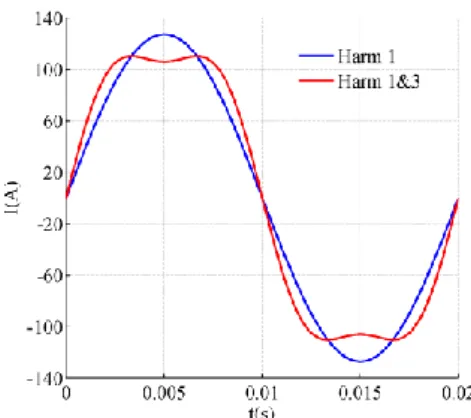
In this paper the previous property is used to reduce the current peak, in order to supply the machine with cheaper inverter or to protect the electronic components. It can be proved that adding a third harmonic current component to the first one can decrease the peak value of this current. Amaximum drop in this value (13.4%) is obtained when the added third harmonic component is 16.4% of the first one. Fig. 15 shows two generated torques in this 5-phase machine with h=12, the first one is produced by the main current harmonic, the other is the result after adding the third harmonic.
7 a. The 5-phase machine torque before and after adding the current 3rd harmonic component (16.4%
of fondamental).
b. The phase current before and after adding the 3rd harmonic component (16.4% of fondmaental). Figure 15. Machine torque with lower current
peak (h=12).
It can be noted that, according to theory of multiphase machine, the third harmonic current has no effect on the torque pulsations for this configuration (since the secondary machine is inactive).In the same time it helps to reduce the current peak by 13.4%. However this technic leads to 2.7% more Joule losses in the windings. This kind of injection could be used, during transient states (as acceleration), to maximize the use of current rating of the Voltage Source Inverter transistors.
C. The cogging torque
The cogging torque sensibility to h is also studied for this 5-phase machine using the same methodology consisting in a coupling between an optimization program in Matlab and the FEM “femm”. The result shows that straight-shape magnets configuration (h=4.16) has the lowest cogging torque. Since 8 slots (40 slots instead of 48) are deleted to adapt the stator to 5 phase winding, the cogging torque of this 5 phase machine is higher comparing with the original PRIUS. However, the level cogging torque is much less important than pulsation due to interaction between harmonic of back-EMF and current. Fig.16 shows the
cogging torque and its RMS value for different h.
a. The cogging torque for different magnet configurations.
b. RMS value of cogging torque for different magnet configurations.
Figure 16. Cogging torque for 5-phase PRIUS type machine.
D. Torque ripple
Lower pulsating torque is one of the interesting advantages of multi-phase machines [9], owing to the fact that the harmonics which interact to disturb the torque have higher ranks. For example in 5 phase machines the first disturbing harmonic for main fictitious machine is the 9th instead of the 5th in 3-phase classic machines [11].
Fig. 17 shows the curves of relative amplitude of torque oscillation, where each curve presents the relative torque oscillation of one configuration (h) according to electrical angle ψe, while the machine is supplied with 5
sinusoidal shifted currents (127A). After observing the curves until ψe =-60
o
, we find that the configurations with 4.16<h<12 have the lowest relative oscillation in torque (less than 10%). To analyze this result the back-EMF frequency spectrums presented in Fig. 14 is studied, it can be seen that the 9th harmonic is almost null in the configurations correspond to lower torque ripples (4.16<h<12), which proves the role of this harmonic in torque ripples. Besides, the results confirms that third, fifth and seven harmonics,
8 which are much more important than with the 3-phase configuration, have no impact of torque pulsation when sinusoidal currents are imposed.
Figure 17. Torque ripple in 3-phase PRIUS type machine (Ip = 127 A).
Figure 18. The average of relative torque ripples over the flux weakening region.
In order to compare torque ripple for different configurations, the average value of torque relative oscillation is calculated along the flux weakening region ψe [-80°,-45°]. Fig. 18 presents this average according to h, where it can be noted that the structure with h=10.96 (PRIUS structure) has also the lowest average of torque relative oscillation (about 8%) all over the flux weakening region. To conclude, despite the fact that a simple winding structure is applied in this 5 phase machine (only one slot per pole and per phase), it generates much less torque ripple through the whole flux weakening region and for all magnet configurations.
E. Flux weakening region
As in the last paragraph, Ld, Lq are calculated
for the main fictitious machine using FEM “femm”, and in order to consider iron saturation this calculation is done for three different load currents (amplitude 127A, 99A, 71A). Fig. 19 presents the calculated values of Ld, Lq according to the magnet open angle. The
value (Lq-Ld) which indicates the added
reluctance torque is presented also.
In order to study the flux weakening region of the 5-phase machine, the same limits as in original PRIUS machine are considered, 500 V Dc Bus, and maximum current amplitude of 127 A (keeping the same linear current density as for 3-phase machine with 212 A). Using the same flux weakening strategy in the last paragraph, and considering last limits, the curves torque-speed, and power-speed of the machine are drawn. Fig. 20 shows the curves which present the torque-speed, and power-speed characteristic of the machine for 5 magnet configurations (5 values of h).
Figure 19. Ld and Lq calculated for 5-phase PRIUS type machine.
As in 3-phase machine it can be noted that, straight-shape magnet configuration (h=4.16 mm) has the best characteristics torque-speed along the flux weakening region, while the configuration with h=14 seems to produce the maximum torque at basic speed.
Fig. 21 shows the torque/power-speed, characteristics of the machine for the same five values of h but with lower maximum current of 99A. Here the reluctance effect is clearer, where the configurations generate different torques at basic speed. The structure with h=14 is the best choice at low speed application (more generated torque), while the straight-shape magnet structure stays the best choice for higher speeds along the flux weakening region.
9 0 2500 5000 7500 10000 12500 15000 0 50 100 150 200 250 300 Speed(RPM) T (N m ) h=4.16 h=8 h=10.96 h=14 h=18 0 2500 5000 7500 10000 12500 15000 0 0.9 1.8 2.7 3.6 4.5x 10 4 Speed(RPM) P( W ) h=4.16 h=8 h=10.96 h=14 h=18
Figure 20. Torque/Power – Speed characteristic for the 5-phase PRIUS type machine for Ip = 127A.
4. Conclusion
This paper studies the effects of magnet pole open angle (h) on torque and flux weakening region of V-shape magnets PRIUS type machine. Moreover similar study is done for a 5-phase machine which has the same type and dimensions of PRIUS. It shows interest of the modification of the number of phases for the drive.
3-phasePRIUS machine structure with h=10.96 mm produces the highest average total torque, due to its high reluctant torque which makes 39% of total torque. Also 3-phase PRIUS structure appears to have very low cogging torque even if the lowest cogging torque is obtained with h=11.5 mm. On the other hand Torque ripples increase notably with magnet open angle, and the structure with (h=8) appears to have the minimum torque ripples all over the flux weakening region (19%) even if 3-phase PRIUS configuration is not so far (22%).
The inductance values Ld, Lq vary also with the
pole angle leading to different flux weakening regions, and this study shows that the structure with straight-shape magnets keeps the highest power through the flux weakening region, while PRIUS and the structure with h=14 mm produce the highest torque at basic speed (before flux weakening).
0 2500 5000 7500 10000 12500 15000 0 50 100 150 200 250 Speed(RPM) T (N m ) h=4.16 h=8 h=10.96 h=14 h=18 0 2500 5000 7500 10000 12500 15000 0 0.5 1 1.5 2 2.5 3 3.5 4x 10 4 Speed(RPM) P( W ) h=4.16 h=8 h=10.96 h=14 h=18
Figure 21. Torque/Power – Speed characteristic for the 5-phase PRIUS type machine for Ip = 99A. The modified machine with five phases and 40 slots produces the same average torque as in three phases case, beside that the 5-phase machine with PRIUS rotor structure (h=10.96 mm) still offers one of the highest average torques. Whereas the lower torque ripples is the most obvious advantage of this 5-phase machine, and PRIUS rotor structure with h=10.96 has the lowest average torque ripples all over the flux weakening region (8%) in comparison with 19% in 3-phase configuration.
The additional degree of freedom offered by the 5 phase is also used to generate the same torque but with 13.4% lower current peak. For the flux weakening the conclusion are the same as for 3-phase configuration. In future works, impact of concentrated windings allowing low torque ripples could also investigated with multiphase configurations.
References
[1] Z. Azar, L.J. Wu, D. Evans, Z.Q.Zhu, “Influence of rotor configuration on iron and magnet losses of fractional-slot IPM machines”, PEMD 2010, Power Electronics, Machines and Drives, April 2010.
[2] G. Cvetkovski, L. Petkavska, “Dynamic Simulation of PM Disc Motor Using
10 MATLAB/Simulink Coupled with Finite Element Method”, EPE 2009.
[3] D. Evans, Z. Azar, L.J. Wu, Z.Q. Zhu, “ Comparison of optimal design and performance of PM machines having non-overlapping windings and different rotor topologies”, Power Electronics, Machines and Drives (PEMD 2010), April 2010. [4] J.R. Figueroa Barnier, “Modélisation des
entrainements à grande plage de vitesse en vue de leur conception”, PhD thesis, University of Laval Quebec, 2008. [5] L. Guo, L, Parsa, “Effects of Magnet
Shape on Torque Characteristics of Interior Permanent Magnet Machines”, Electric Ship Technologies Symposium, ESTS 2009.
[6] J.S. Hsu, C.W. Ayers, C.L. Coomer, “Report on TOYOTA/PRIUS motor design and manufacturing assessment”, OAK Ridge National Laboratory,
www.ornl.gov, 2004.
[7] M. Kamiya, “Development of Traction Drive Motors for the Toyota Hybrid System”, IEEJ Transactions on Industry Applications, Vol. 126, No. 4, pp.473-479, 2006.
[8] E. Levi, “Multiphase Electric Machines for Variable-Speed Applications”, IEEE Transactions on Industrial Electronics, Vol. 55, No. 5, May 2008.
[9] F. Locment, E. Semail, F. Piriou, “Design and Study of a Multiphase Axial-Flux Machine”, IEEE Trans. Mag., Vol. 42, No. 4, April 2006.
[10] M. Olszewski, “Evaluation of 2004 TOYOTA PRIUS Hybrid electric drive system”, OAK Ridge National Laboratory, www.ornl.gov, 2006.
[11] F. Scuiller, J-F. Charpentier, E. Semail, S. Clénet, “Comparison of two 5-phase Permanent Magnet machine winding configurations. Application on naval propulsion specifications.”, IEMDC’07, IEEE Transactions on Inductry Applications, Vol. 1, pp. 34-39, May 2007.