Science Arts & Métiers (SAM)
is an open access repository that collects the work of Arts et Métiers Institute of
Technology researchers and makes it freely available over the web where possible.
This is an author-deposited version published in: https://sam.ensam.eu
Handle ID: .http://hdl.handle.net/10985/18599
To cite this version :
Dhanush VITTAL SHENOY, M. S. SHADLOO, Jorge PEIXINHO, Abdellah HADJADJ - Direct numerical simulations of laminar and transitional flows in diverging pipes - International Journal of Numerical Methods for Heat and Fluid Flow - Vol. 30, n°1, p.75-92 - 2019
Any correspondence concerning this service should be sent to the repository Administrator : [email protected]
Direct numerical simulations of
laminar and transitional flows
in diverging pipes
Dhanush Vittal Shenoy
and
Mostafa Safdari Shadloo
Complexe de Recherche Interprofessionnel en Aérothermochimie, Institut National des Sciences Appliquées, INSA Rouen Normandie,Saint Etienne du Rouvray, Haute-Normandie, France
Jorge Peixinho
LOMC, CNRS and Université Le Havre Normandie and Laboratoire PIMM, CNRS, Arts et Métiers, CNAM, HÉSAM Université, Paris, France, and
Abdellah Hadjadj
Complexe de Recherche Interprofessionnel en Aérothermochimie, Institut National des Sciences Appliquées, INSA Rouen Normandie,
Saint Etienne du Rouvray, Haute-Normandie, France
Abstract
Purpose –Fluid flows in pipes whose cross-sectional area are increasing in the stream-wise direction are prone to separation of the recirculation region. This paper aims to investigate such fluid flow in expansion pipe systems using direct numerical simulations. The flow in circular diverging pipes with different diverging half angles, namely, 45, 26, 14, 7.2 and 4.7 degrees, are considered. The flow is fed by a fully developed laminar parabolic velocity profile at its inlet and is connected to a long straight circular pipe at its downstream to characterise recirculation zone and skin friction coefficient in the laminar regime. The flow is considered linearly stable for Reynolds numbers sufficiently below natural transition. A perturbation is added to the inlet fully developed laminar velocity profile to test the flow response to finite amplitude disturbances and to characterise sub-critical transition.
Design/methodology/approach –Direct numerical simulations of the Navier–Stokes equations have been solved using a spectral element method.
Findings – It is found that the onset of disordered motion and the dynamics of the localised turbulence patch are controlled by the Reynolds number, the perturbation amplitude and the half angle of the pipe.
Originality/value –The authors clarify different stages of flow behaviour under the finite amplitude perturbations and shed more light to flow physics such as existence of Kelvin–Helmholtz instabilities as well as mechanism of turbulent puff shedding in diverging pipe flows.
Keywords Diverging pipe flows, Localized turbulence, Transitional flow, Direct numerical simulations
1. Introduction
The transition from laminar to turbulent flow in pipes with circular cross-section is a basic research problem that is of both fundamental and practical importance. The mechanisms that cause flow instabilities and the dramatic increase in mixing, heat transfer and drag friction coefficients are still poorly understood. The laminar expansion flow is characterised by a long thin recirculation region. A critical issue in this problem is related to separation-induced transition. Indeed, due to low-frequency unsteadiness in the separated region, a significant energy loss is incurred along the transition (Dupont et al., 2006;
Ganapathisubramani et al., 2007; Rodríguez et al., 2013). This phenomenon is critical in many industrial situations such as enclosed wind turbines, pipeline transports, thrust-vectoring nozzles, diffusers and turbo-machines.
The emergence of low-frequency oscillations of the laminar separation bubble is sometimes responsible for the fluctuating pressure in the global flow field (Nguyen et al., 2002; Sajben et al., 1984). At later stages of the transitional regime, laminar-turbulent patterns and properties of the localised turbulence have been studied in plane Poiseuille flow (Farano et al., 2015; Lemoult et al., 2012). However, there is a scarcity of the data for diverging pipe flows. For such geometries, when the flow at the inlet is turbulent, it may undergo relaminarisation downstream. If the inlet flow is laminar, for some range of subcritical Reynolds numbers, localised disordered patches are observed depending on the exact geometry of the expansion region. In the past decades, many studies have been performed for the flow in the case of two-dimensional abrupt expansion (Drikakis, 1997;
Fearn et al., 1990;Milos et al., 1987), which showed consistently that the axial length of the recirculation region increases linearly, from the expansion, with the Reynolds number. Here the Reynolds number, Re = Ud/!, where U is the bulk velocity, d, the inlet pipe diameter and ! is the kinematic viscosity of the fluid. The existence of breaking of symmetry at a critical Re confirmed the existence of a bifurcation. The experimental studies (Mullin et al., 2009;
Sreenivasan and Strykowski, 1983) revealed that the reattachment point oscillates by a complex interaction of flow oscillations and the re-establishment of the recirculation region downstream of the expansion region. The mean flow interacts with the recirculation region creating shear. Latornell et al. (Latornell and Pollard, 1986) observed experimentally the shear instability and proposed that the existence of unstable mode might be explained by instabilities arising due to the streamline curvature or centrifugal instability. Later, studies performed on the backward facing step byBeaudoin et al. (2004) further supported the detached flow is consistent with the centrifugal instability.
For sudden pipe 1:2 expansion, the global flow stability analysis (Cliffe et al., 2011;
Sanmiguel-Rojas et al., 2010) suggests the critical Re for linear instability is at least 5000. Moreover, a detailed study of transient growth stability was performed byCantwell et al. (2010), which showed that the sudden expansion can amplify the energy of infinitesimal perturbations up to six orders of magnitude before its decay. The difference between the critical Re in experiments and simulations may be explained by imperfections in the experiment. Therefore, the values of critical Re should be dependent both on the perturbation nature and its amplitude. Hence, numerical simulations with well-defined finite amplitude perturbation are required to better understand the underlying mechanism. Three-dimensional direct numerical simulations (DNS) have been carried out for sudden expansion pipe flows by several authors (Moallemi and Brinkerhoff, 2018;Sanmiguel-Rojas and Mullin, 2012;Selvam et al., 2015;Sparrow et al., 2009) with different perturbations:
! the transverse velocity component (tilt) perturbation at the inlet, via a uniform
cross-flow, added to the Hagen–Poiseuille flow (Sanmiguel-Rojas and Mullin, 2012;
The last vortex perturbation has been implemented to observe a less abrupt transition to localised disordered. It also reproduced the finite amplitude thresholds for transition experiments in the subcritical regime (Lebon et al., 2018) and the bursting or breathing mode often described also in experiments (Latornell and Pollard, 1986;Lebon et al., 2018).
For diverging flows, a general two-dimension stability problem, known as the Jefferey– Hamel problem, is known to have infinite number of solutions. Specifically,Haines et al. (2011)obtained sequences of nested neutral curves corresponding to steady flow solutions. Two-dimensional axisymmetric Navier–Stokes simulations also reported the effect of the diverging angle and Re on the onset of the laminar recirculations (Peixinho and Besnard, 2013). In diverging channel flow, Jobkar et al. (Jotkar and Govindarajan, 2019;Jotkar et al., 2015) further showed the effect of the angle and the expansion ratio. Small angles delay the onset of the critical Re and small expansion ratios also delay the critical Re. For diverging expansion pipe flow, the tilt perturbation has been tested (Selvam et al., 2015) for a diverging pipe, with diverging half angle u ^ 27° with expansion ratio 2, which showed the existence of hysteresis behaviour as a function of Re. In the related problem of stenotic flow, a common perturbation is the offsets of the stenosis throat (Samuelsson et al., 2015;Vétel et al., 2008). The present paper presents new simulation results for different diverging angles and Re numbers. The perturbation superimposed to the initial laminar flow creates an asymmetry in the recirculation region downstream, which oscillates due to the Kelvin– Helmholtz instability, similar to that of a wake behind axisymmetric bluff bodies (Bobinski et al., 2014;Le Clainche et al., 2016). At higher Re, the recirculation breaks to form a localised disordered patch.
The goal of the present investigation is to numerically model the diverging expansion pipe flow with a controlled localised vortex perturbation added at the inlet. In Section 2, the numerical method is presented. Next, in Section 3, the results for the thresholds and the spatio-temporal dynamics of the disordered patches are discussed. Finally, the conclusions are stated in Section 4.
2. Numerical method and problem setup
The simulations are performed by solving the unsteady incompressible three-dimensional Navier–Stokes equations for viscous Newtonian fluids in its non-dimensional form as:
r " u ¼ 0; (1)
@u
@t þ r " uuð Þ ¼ 'rp þ 1
Re r2u; (2)
where u = (ux, uy, uz) is the velocity vector, t is the time and p is the pressure. The equation is
made non-dimensional by the inlet diameter d, kinematic viscosity ! and the inlet bulk velocity U which will lead to the time scale of d/U. The pressure p is also scaled with dynamic pressure rU2, r being the fluid density.
The laminar Poiseuille flow through the inlet of the gradual expansion is characterised by the appearance of a recirculation region sketched onFigure 1, noted Lr, localised along
the wall near the expansion. The expansion region is characterised either by the expansion length L1or by its half-angle u . The following boundary conditions are imposed:
uz¼ 2U 1 ' 4rð 2Þ x 2 Inlet (3)
u ¼ 0 x 2 Wall (4)
p " n ' n " ru=Re ¼ 0 x 2 Outlet (5)
Equation (3)corresponds to fully developed Hagen–Poiseuille flow at the inlet,equation (4)
imposes no-slip boundary condition at the wall, andequation (5)enforces a weak Neumann boundary condition for the velocity at the outlet. The latter has been well documented and known to minimise the possibility of numerical oscillations and reflections of the outgoing waves, normal to the outlet and directed outside of the domain.
The linear growth of the recirculation length for gradually expansion pipe flows, with an expansion ratio of D/d = 2 for seven different diverging angles u are considered, where D is the diameter of the downstream pipe. Re is ranging from 20 to 3500.
The spatial discretisation ofequations (1)and(2)is done based on the spectral element method (Patera, 1984) solver, called NEK5000 (Fischer et al., 2008). Spectral element method is a subclass of Galerkin and the equations are reduced to their weak form and spatially approximated by Galerkin approximation. In each element, both velocity and pressure space are solved with same Nth order Legendre polynomial approximation, integrals are discretized with Gauss–Legendre quadrature on Gauss–Lobatto–Legendre points to obtain PN' PNsplitting-scheme formulation. The spectral mesh is created with NEK5000 having
different diverging lengths as shown in theTable I.
For the time integration, semi-implicit time stepping method with third-order accuracy is used, where viscous terms treated with implicit backward differentiation formula of third order and non-linear terms are approximated with explicit extrapolation scheme of third order (Fischer et al., 2008).
3. Results and discussion
The code used here, NEK5000 (Fischer et al., 2008), have been extensively validated in the literature and acknowledged in the turbulence community, several studies have been performed on transitional and separated flows (Ducoin et al., 2017;Méndez et al., 2018;
Mollicone et al., 2017). 3.1 Numerical convergence
The grid convergence is performed by keeping the total number of spectral elements constant and increasing the polynomial orders of N = 5 to 7. Two different criteria are validated: the recirculation length, Lr, and the average wall skin friction, Cz. While the
former is simply calculated by knowing the stream-wise location at the wall where the
Figure 1.
Schematic of the fluid domain 2d L0 = 150d L1 5d d Lr θ
stream-wise velocity changes its sign, the latter is calculated, in the cylindrical coordinate, from: Czð Þ ¼t ! 4pd2LU2 ðL z¼0 ð2p u¼0 @uz @r " # r¼drdu dz: (6)
The results of mesh convergence are presented inTable II. It is found that the polynomial order N = 5 is sufficient to resolve both the recirculation length, Lr, and the drag coefficient
Cz. The same is observed for the critical Re of transition with the less than 1 per cent
deviation. It is noted that each hexahedral element consists of P3 number of Gauss–
Legendre–Lobatto points which gives more than five solution points under yþ = 1.
Therefore, the mesh is suitable to capture the flow physics appearing from near wall to the centreline flows. Noted that the presented mesh is similar to the one used bySelvam et al. (2015)andNguyen et al. (2019).
The tests indicate that the downstream length, L0, have a small effect on Lr and a
significant influence on the drag coefficient. This is done for the diverging pipe with the diverging half angle of u = 458because it has the longest recirculation length for Re = 1000.
One shorter and one longer downstream pipe lengths, i.e. 125d and 175d, are investigated. Results showed no significant changes in the recirculation length confirming that the extent of the domain is sufficient to avoid the influence from outlet boundaries. However, the Cz
increased with increasing the pipe length. This is mainly because of extended surface length, which appears in the integrationequation (6)for larger domain length and increases the wall shear drag force.
3.2 Laminar flow
The laminar Poiseuille flow through a gradual expansion is characterised by the appearance of a recirculation region localised along the wall near the expansion, seeFigure 1. Here, the length of reattachment zones in downstream pipe, Lr, are calculated for all the geometries
and plotted as a function of L1at Re = 1000 and 2000 as shown in theFigure 3(a). It is seen
that the pipe with the diverging half angle of u = 458has the largest recirculation length,
Table I. Numerical setup and mesh resolution for different diverging pipes
Case L1/d u(radians) Elem. numb. Mesh (millions)
1 0.5 45.0 (0.25p) 74 640 9.33 2 1 26.56 (0.145p) 74 880 9.36 3 2 14.04 (0.078p) 75 360 9.42 4 4 7.181 (0.039p) 76 320 9.54 5 6 4.78 (0.026p) 77 280 9.66 Table II. Convergence results for L1= 0.5d (u= 45°) at Re = 1000
Case N L0/d Elem. num. Mesh (million) Lr/d Cz
1a 5 150 74 640 9.33 43.5 0.343 1b 6 150 74 640 16.1 43 0.354 1c 7 150 74 640 25.6 43.5 0.35 1d 5 125 62 640 7.83 43.5 0.184 1e 5 175 86 640 10.83 43.5 0.508
which is around Lr= 45d for Re = 1000 and Lr= 88d for Re = 2000. L1is decreasing with the
diverging length or the angle as well as Re. It is also found that for a given Reynolds number the recirculation length has a linear relationship with the diverging length or half angle. This relationship for two concerned Reynolds number is depicted inTable II.
The skin friction coefficient, Cz, for different diverging lengths L1or angle u at Reynolds
numbers of Re = 1000 and 2000 are also shown in Figure 3(b). It is noted that the recirculation bubble in the case of lower half diverging angles (for instance L1= 6d with the
half diverging angle of u = 78) are much thinner than of those with higher half diverging
angles (for instance for L1= 0.5d with the half diverging angle of u = 458), where the Cz
increases as L1increases. The reason for the differences in the mean flow is much closer to
the wall, and the shear inside the bubble is higher. Another reason is due to the fact that the recirculation length and as consequence, the negative component of shear is decreasing by decreasing the pipe diverging half angle. Once more a linear relationship is observed. Additionally, it can be seen that all of the skin friction coefficients are negative for the case of Re = 2000, which is due to their larger recirculation lengths and their counter flow Figure 2.
Spectral element mesh
Figure 3. Effect of the non-dimensional expansion length L1/d
as a function of (a) the non-dimensional recirculation length, Lg/d, (b) the skin friction coefficient, Cz (a) (b) 1,000 2,000
Note: The non-dimensional expansion length can also be expressed in terms of angle, θ,
participation in the skin friction coefficients. Similar to recirculation lengths, a linear behaviour for Czas a function of L1is found and is presented inTable III.
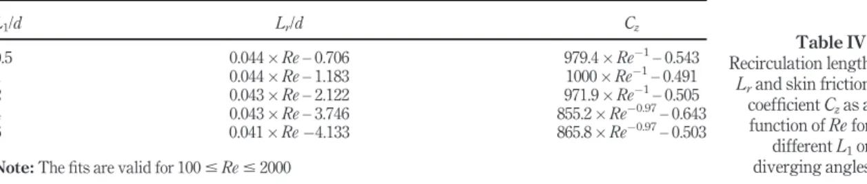
It is useful to know the effect of Re on the recirculation length, LRand skin friction
coefficient, Cz. The linear growth of the recirculation length for different gradually expanded
pipe flows as a function of Re (ranging from Re = 10 to 2000 based on the inlet diameter) are presented inFigure 4(a). The recirculation length increases linearly as a function of Re and the slope is almost independent of the diverging half angle (see alsoTable III). Additionally, the simulation results of u = 26.6° (L1= 1d) recovered a similar slope as in the work of
Peixinho and Besnard (Peixinho and Besnard, 2013) for diverging pipe with the expansion ratio of D/d = 7.3. Surprisingly, for the range of reported Re, the skin friction coefficient Cz
decreases monotonically with an increment in the Re as is illustrated inFigure 4(b). This is due to the fact that the recirculation length expands significantly in the outlet pipe.
Clearly, the recirculation cannot continue to grow linearly with Re. This raises the question of the flow naturally transitioning. Many studies such asFuruichi et al. (2003)have shown this behaviour for sudden expansion flows. However, there are many ambiguities for the critical Reynolds number. For instance, the numerical study on the global stability analysis by Sanmiguel–Rojas et al. (Sanmiguel-Rojas and Mullin, 2012) have shown the symmetry up to Re ( 3273, which are a comparatively much higher value than the experimental studies reported bySreenivasan and Strykowski (1983). In the current work, the Reynolds number is increased gradually and the changes in recirculation length and skin friction coefficient are monitored to pin point the natural transition Reynolds number.
Results for two extreme cases, i.e. L1= 0.5d and 6d, are presented inFigure 5. The critical
Re for natural transition in present cases are found to be around Re ( 3000 for all geometries, where, from this point on, the Lr and Cz start to decrease and increase,
respectively. The reason for decreasing the Lr is that the flow gains enough energy to
pushes the recirculation bubble back and to finally break it. On the other hand, it causes higher shear gradient at the wall and as a consequence an augmentation in the skin friction coefficient. It is noted that the results for different diverging angle pipe flow in laminar regimes indicate that the presence of a gradual diverging section has limited influence on the
Table III. Results of least-square fits of the simulations results for the relationship between L1versus Lr and Cz Re L1/d 1000 '0.71 ) Lrþ 31.21 1000 49.05 ) Czþ 10.85 2000 '0.59 ) Lrþ 52.77 2000 96.83 ) Czþ 10.85 Table IV. Recirculation length Lrand skin friction
coefficient Czas a function of Re for different L1or diverging angles L1/d Lr/d Cz 0.5 0.044 ) Re – 0.706 979.4 ) Re'1–0.543 1 0.044 ) Re – 1.183 1000 ) Re'1–0.491 2 0.043 ) Re – 2.122 971.9 ) Re'1–0.505 4 0.043 ) Re – 3.746 855.2 ) Re'0.97–0.643 6 0.041 ) Re '4.133 865.8 ) Re'0.97–0.503
recirculation length as well as critical naturally transiting Reynolds number. However, this necessarily provides the Re limit to study the induced sub-critical transition in the next section, where the fully developed laminar simulations will be used as the base flow (in another word as the initial condition) for the simulations with different perturbation amplitudes.
3.3 Sub-critical transition
The sub-critical transition is achieved by adding a vortex perturbation to the converged laminar solution. It takes around t = 500 s to reach steady state for the lowest studied Re. Therefore, results are reported at t = 1000 s where the initial unsteadiness are left the computational domain. Here, the time-step is kept constant at D t = 0.001 which yielded Courant’s number less than 0.3. Now, a vortex perturbation at the inlet as in previous simulations in sudden expansion flow (Nguyen et al., 2019;Selvam et al., 2016). It a radius of 0.25d and its centre is located at off-centre to break the symmetry of the flow and deflects the recirculation regions. The magnitude of the perturbation amplitude A can be varied from 0.01 to 1. In the present simulations, the perturbation of finite amplitude A is added to the base laminar flow calculated with A ¼ 0 at t = 900 s where the flow propagates through the pipe. Overall, more than 120 DNSs are performed for different A, 5 different diverging angles, L1or u and 6 values of Re. The simulation results are summarised inFigure 6. First,
Figure 4. (a) Non-dimensional length of the recirculation region as a function of Re for different diverging lengths, L1; (b) change in skin friction, Cz, as a function of Re for different diverging lengths, L1 Figure 5. The non-dimensional length of the recirculation, Lg/d,
and the drag, Cz, as a
function of Re for (a) L1= 0.5d and (b) L1=
at low Reynolds numbers, sharper diverging angles are more receptible to the inlet perturbation and flow becomes turbulent at lower A. However, this is inverse for larger Reynolds numbers, i.e. the flow becomes more receptible for more gentle angles. Second, the critical perturbation amplitude for the flow transition not only depends on the Reynolds number but also is sensitive to the angle of diverging pipe. Third, the critical perturbation amplitude can be fitted using a power-law scaling as a function of Reynolds number, i.e. A / Re'a, where a being a constant. These functions are illustrated inFigure 6and are
summarised inTable V. Noted that the results for the sudden expansion pipe flow (i.e. L1=
0) is taken fromNguyen et al. (2019).
Interestingly, the sudden expansion pipe flows show higher stability, i.e. larger negative coefficient for a. This is probably due to the fact that the recirculation bubble is attached to the expansion position unlike the cases of diverging pipes, here with L1= 0.5d for the sake of
Figure 6. Critical A as a function of Re for (a) L1= 0.5d, (b) L1= 1d,
(c) L1= 2d and
(d) L1= 6d
Table V. Results of the least-squares fit of the power-law exponent,
a, for the dependence of the critical amplitude A as a function of Re for different diverging pipe lengths: A / Re'a L1/d 0 0.5 1 2 6 a 2.8 2.1 3.6 4.6 4.6
comparison, which slips downstream, i. e. its beginning is somewhere between the start and the end of diverging area. However, the power law constant a increases, in its absolute sense with decreasing the pipe diverging half angle.
It is noted that both skin friction coefficient [equation (6)] and the space-time diagram are used to identify the state of flow. The flow is visualised using space time diagram which is computed by plotting axial velocity difference at the centre line between perturbed and base flow (calculated withA ¼ 0) as:
uz0ð0; 0; z; tÞ ¼ uzð0; 0; z; tÞ ' uz;bð0; 0; zÞ (7)
Here, 1,500 equidistant probes are used to record the centre-line velocity at particular interval depending on the resolution. The base flow, uz,b(0,0, z), is the closest laminar state
without any perturbation for a given Reynolds number. The skin friction coefficient is another criterion that shows a good indication of the turbulent state. Therefore, in all of presentations, the average skin friction coefficient is superimposed on the space time diagram in this section.
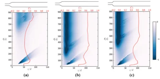
Examples of space-time diagrams for the L1= 1d case at Re = 1600 are shown inFigure 7
for three different perturbation amplitudes, where the colour is the indication that the flow at the centre line has been changed from its reference value, which can be used as an indication for the transitional and turbulent flows. InFigure 7(a)one can see dark blue colour at initial times that fades away downstream and by passing time. This is the signature of the initial perturbation which was for this case A ¼ 0:02. It can be seen that this signature leaves the computational domain at t = 500 s. At this time, the initial jump in the skin friction coefficient, caused by the initial perturbation, decreases and flow stays laminar (for the reported simulation time).
By increasing the perturbation amplitude to A ¼ 0:04, the finite amplitude perturbation is accumulated and amplified inside of the domain and breaks the flow symmetry long after the initial perturbation signature left the domain [Figure 7(b)]. This state is considered as a turbulent state as both space-time diagram and skin friction coefficient show strong velocity fluctuations and rise in value, respectively. It is noted that the states shown inFigure 6by ) sign are laminar in the reported period time (here is t = 900 s), but they finally they break the flow symmetry and make it turbulent if we wait long enough (here is t = 1500 s). Such
Figure 7. Space-time diagram for L1= 1d at Re = 1600 for different perturbation amplitude A at (a) A ¼ 0:02 (b) A ¼ 0:04 and (c) A ¼ 0:08
behaviour is also reported in detail for sudden expansion pipe flows in (Nguyen et al., 2019) by discussing the possibilities of hysteresis in such configuration and is not in the scope of current work.
Further increment in the perturbation amplitude to A ¼ 0:08 is shown inFigure 7(c). The perturbation amplitude is strong enough to break the flow symmetry and makes it turbulent even before leaving the computational domain. The intermittent behaviour is clearly observed for this case from the space-time diagram. If the amplitude of added perturbation is slightly higher than the critical value, the periodic breakdown can be observed for all the cases. It is noted that although such behaviour was reported before for sudden expansion pipe flows (Lebon et al., 2018;Lebon et al., 2018;Nguyen et al., 2019), to the authors’ best knowledge, it is the first time that is shown for the diverging pipe flows. This intermittency is not limited to the present case, i.e. L1= 1d, and it also presents for other diverging angles.
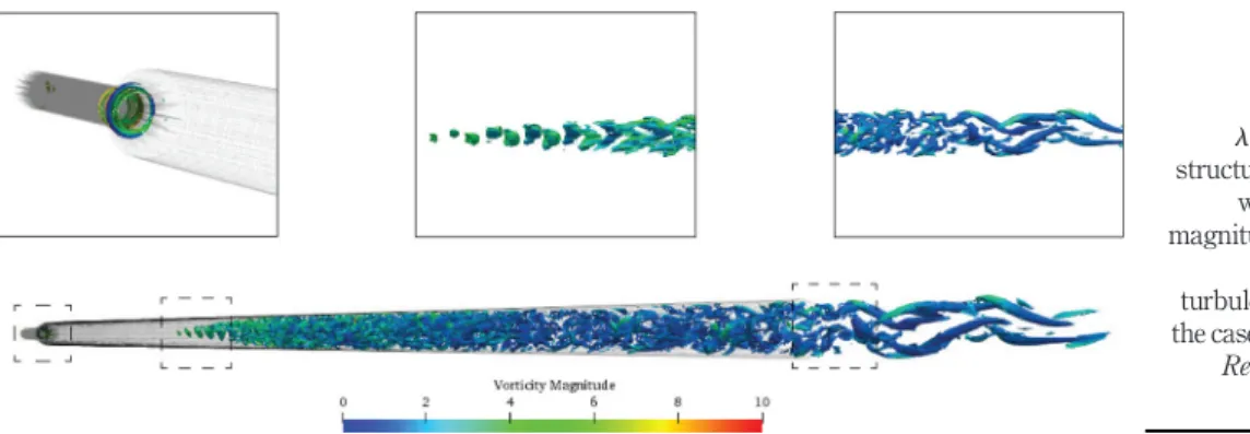
Coherent structures visualised using l2criteria coloured with the vorticity magnitude
for the Figure 8 are presented in Figure 10 to visualise the vortical structures. Three different regions correspond to:
(1) initial vortical perturbation structure;
(2) birth/growth of the perturbation disturbance; and (3) the decay of turbulent patch are highlighted in this figure.
The flow is energetic and the turbulent patch is long enough to cause substantial difference in its pressure field upstream and downstream, which interacts with the velocity field upstream repeatedly recovering the recirculation zone. This in return causes the periodic movement of the patch itself such as the one reported inFigure 7(c). The intermittent behaviour of the turbulent patch was studied experimentally and numerically in the case of sudden expansion pipe flows by Sreenivasan et al. (Sreenivasan and Strykowski, 1983) and more recently by
Nguyen et al. (2019), respectively. If the amplitude of perturbation is slightly higher than the critical, the flow exhibits periodic appearance as shown in theFigure 7(b). It is then followed by periodic movement of the turbulent patch. Further increase in the perturbation amplitude, will lead to stationary turbulent flow due to the nature of the added perturbation. It is noted that only one appearance of turbulent patch is reported inFigure 7(b). Similar behaviours were reported recently for sudden expansion pipe flows, where more details on such behaviour can be found inLebon et al. (2018)andNguyen et al. (2019).
Peculiar behaviour is found for the case of L1= 0.5d and to some extent for L1= 1d.
Surprisingly, for this case, the critical disturbance amplitude increased up from Re = 1200 to
Figure 8. l2iso-surface structures coloured with vorticity magnitude showing the localised turbulent patch for the case of L1¼ 1d,
Re = 1600 with A ¼ 0:08
2000 and then decreased, seeFigure 6. This is because, at this moderate ranges of Re, the flow behaves highly unstable for considerably small perturbation amplitudes and the instability creeps in if enough time is provided. This can be seen, for instance, in the space-time diagram ofFigure 9. This can be suspected to be due to the fact that although the flow has less energy, the streamline curvatures are higher close to the expansion zone when compared to higher Reynolds number flows (i.e. for Re > 2000); however, the flow is still possessing high enough energy to cause the instability. On the contrary, for flows with Re < 1200, although the curvature increases close to the expansion area, the flow possessing lesser energy to transit the flow. Therefore, higher values of perturbation amplitudes are needed. Finally, for more energetic flows, i.e. for Re > 2000, though the streamline curvature close to the expansion area are very small, a small perturbation can cause a turbulent state instantly after inserting the perturbation. Similar behaviour was observed in the case of sudden expansion pipes (Cantwell et al., 2010).
Figure 9(b) and (c) shows the space-time diagrams at the critical amplitudes of perturbation for a Reynolds number below this range, i.e. at Re = 1000, for the flow inside diverging pipes with the diverging length of L1= 1d and 0.5d, respectively. As
can be seen in these figures, flow needs a relatively large perturbation amplitude to break the flow symmetry. Noted that for higher Reynolds numbers, i.e. Re > 2000 and 1600 for L1= 0.5d and 1d, respectively, the turbulent signature in space-time diagrams
at critical amplitudes are the same asFigure 9(b)and(c); therefore, for brevity, they are not shown here.
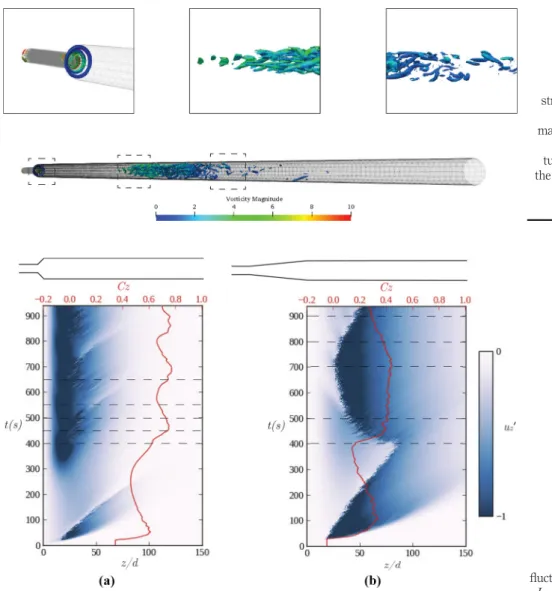
Coherent structures visualised using l2criteria coloured with the vorticity magnitude
correspond for this specific [i.e.Figure 9(b)]case is presented inFigure 10. Here, we choose the flow inside diverging pipe with the diverging length of L1= 0.5d at Re = 1200 for the
perturbation amplitude of A ¼ 0:025 as an example. In this case, the flow was laminar in the reported time, i.e. t = 900 s after adding the perturbation on the base flow; therefore, we waited till t = 1200 s to see the manifested turbulent patch.
Comparing with Figure 12, one can see that the birth and growth of coherent structures are almost similar in both cases, which are due to Kelvin–Helmholtz instabilities at the beginning of the patches. However, the turbulent patch is considerably smaller inFigure 8when compared to its counterpart inFigure 9(a). For
Figure 9. Space-time diagrams at critical amplitude of (a) A ¼ 0:04 for L1= 1d at Re = 1200, (b) A ¼ 0:175 for L1= 1d at Re = 1000 and (c) A ¼ 0:155 for L1= 0.5d at Re = 1000
the latter case, however, the flow possesses less energy and the patch is not sufficiently elongated to cause a strong pressure difference along it. Here, the active part of the turbulent patch is relatively short, and the flow has a behaviour very similar to the one presented inFigure 9(a).
Figure 11presents the time evolution of the centreline fluctuation velocity, uz0, for
diverging pipe of different u corresponding to L1= 0.5d (u = 458) and L1= 6d (u = 4.88)
Figure 11. Space-time of the axial velocity fluctuation, uz0, for (a)
L1= 0.5d, Re = 1000 with A ¼ 0:165 and (b) L1= 6d, Re = 2000, with A ¼ 0:165 Figure 10. l2iso-surface structures coloured with vorticity magnitude showing the localised turbulent patch for the case of L1= 0.5d,
Re = 1200 with A ¼ 0:025
at Reynolds number of Re = 1000 and 2000, respectively. In both cases, A ¼ 0:165 is above the threshold of the critical perturbation amplitude. Again, the early time of the perturbation evolution looks similar with a typical cusp shape that grows and decays and re-manifest again at Re = 1000 and remains before it leaves the domain and grows at Re = 2000.
The main difference between the case at Re = 1000 and 2000 is that the localised turbulence patch has smaller sweep length in stream-wise direction for Re = 1000. For this case, the begging of the turbulence patch moves back and forward around the z/d ^ 15. Whereas for Re = 2000, the localised turbulent patch moves axially upstream and downstream within the pipe with between the z/d ^ 25 to z/d ^ 80. The reason for this behaviour seems to be due to the perturbation amplitude level with respect to its critical amplitude for the given pipe geometry and at the given Reynolds number.
For Re = 1000, the effect of the perturbation of A ¼ 0:165 in the diverging pipe L1= 0.5d
is better observed using the vorticity field as depicted inFigure 12. The lower part of the recirculation region grows towards the centreline of the pipe and Kelvin–Helmholtz like waves appear downstream with a wavelength similar to the pipe diameter. They seem to be first symmetric at 400 s, then asymmetric at 450 s and they breakup into a localised turbulent patch at 500 s, which partially decays at 550 s. The process described above repeats with the period of t ( 250 s.
For the diverging pipe with L1= 6d, the axial position of the subcritical turbulent patch is
located further downstream than in the previous case and the case of sudden expansion pipe flows (Nguyen et al., 2019; Selvam et al., 2016). Figure 13 presents the vorticity field indicating that the same type of Kelvin–Helmholtz waves appear downstream. The active part of the turbulent patch is relatively short, typically 8 to 10d and its intermittent time period is almost twice as the previous case t ( 530 s. As can be seen, although many similar phenomena exist for different diverging pipe flows, the consequent subcritical turbulent patch topology and dynamics are strongly depend on the diverging half angle, Reynolds number and the perturbation amplitude with respect to the critical value.
Figure 13. Vorticity field of the turbulent patch for L1= 6d, Re = 2000
and A ¼ 0:025 at time 400, 500, 700, 800 and 900 s Figure 12. Vorticity maps of the turbulent patch for L1= 0.5d, Re = 1000,
and A ¼ 0:0165 at time 400, 450, 500, 550 and 650 s
Therefore, several detailed works are needed to characterise each of these factors. This is the subject of our future works.
4. Conclusion
In the current work, DNS of separated flows inside diverging pipes was investigated. Five diverging lengths of L1=0.5d, 1d, 2d, 4d and 6d corresponding to diverging half angles of
u = 45, 26.5, 14, 7.2 and 4.7°, respectively, were studied for Reynolds numbers ranging from
20 < Re < 3500. Several DNSs were performed for the laminar and transitional (both critical and sub-critical transitions) flows.
In the laminar regime, it was found that for a given Reynolds number both normalised recirculation length Lr/d and skin friction coefficient Czare linear functions of expansion
length L1/d. Noted that the slope of these linear functions are different at different Reynolds
numbers. Additionally, it was found that for a given diverging pipe, the normalised recirculation length Lr/d is linearly depends on Re, for Reynolds numbers ranging from 100
to 2000. Although, Lr/d increases with decreasing L1/d, the slope of proposed linear
correlations are the same regardless of pipes’ diverging half angle. It was also found that Cz
is monotonically decreasing with an increment in the Reynolds number with Cz! Re'1,
regardless of pipes’ diverging half angles.
By increasing the Reynolds number natural transition to turbulent appeared at Re ( 3000 in our system. This critical Reynolds number for natural transition was independent of pipes’ diverging half angle and was in close agreement with the previous finding of Sanmiguel–Rojas (Sanmiguel-Rojas and Mullin, 2012) and Nguyen et al. (Nguyen et al., 2019) for sudden expansion pipe flows.
Finite amplitude vortical perturbations were then added to the steady state laminar flow in order to disturb the flow and study the sub-critical transition in diverging pipes. Different states of flow were characterised, basically by space-time diagrams and skin friction coefficient magnitudes. It was found that the sub-critical Reynolds number of transition can be described by a power-law relation with the perturbation amplitude in the form of A / Re'a.
Additionally, different flow regimes were reported using two-dimensional vorticity maps as well as three-dimensional coherent structures using l2 criterion. Although, the
mechanism of the birth and growth of turbulent patches were look liked the same for different flow parameters, the size and the patches dynamics were quite different and were related to the diverging half angle, perturbation amplitude and Reynolds number. The later needs detailed investigation that is postponed to our future works.
References
Beaudoin, J.-F., Cadot, O., Aider, J.-L. and Wesfreid, J.E. (2004), “Three-dimensional stationary flow over a backward-facing step”, European Journal. Mech.-B/Fluids, Vol. 23 No. 1, pp. 147-155, available at:https://doi.org/10.1016/j.euromechflu.2003.09.010
Bobinski, T., Goujon-Durand, S. and Wesfreid, J.E. (2014), “Instabilities in the wake of a circular disk”, Physical Review. E, Statistical, Nonlinear, and Soft Matter Physics, Vol. 89 No. 5, p. 053021 available at:https://doi.org/10.1103/PhysRevE.89.053021
Cantwell, C.D., Barkley, D. and Blackburn, H.M. (2010), “Transient growth analysis of flow through a sudden expansion in a circular pipe”, Physics of Fluids, Vol. 22 No. 3, p. 034101 available at: https://doi.org/10.1063/1.3313931
Cliffe, K.A., Hall, E.J.C., Houston, P., Phipps, E.T. and Salinger, A.G. (2011), “Adaptivity and a posteriori error control for bifurcation problems II: incompressible fluid flow in open systems with Z2
symmetry”, Journal of Scientific Computing, Vol. 47 No. 3, pp. 389-418, available at:https://doi. org/10.1007/s10915-010-9453-3
Drikakis, D. (1997), “Bifurcation phenomena in incompressible sudden expansion flows”, Physics. Fluids, Vol. 9 No. 1, pp. 76-87, available at:https://doi. org/10.1063/1.869174
Ducoin, A., Shadloo, M.S. and Roy, S. (2017), “Direct numerical simulation of flow instabilities over savonius style wind turbine blades”, Renew. Energy, Vol. 105, pp. 374-385, available at:https:// doi.org/10.1016/j.renene.2016.12.072
Dupont, P., Haddad, C. and Debiéve, J.F. (2006), “Space and time organization in a shock-induced separated boundary layer”, Journal of Fluid Mechanics, Vol. 559, pp. 255-277, available at: https://doi. org/10.1017/S0022112006000267
Farano, M., Cherubini, S., Robinet, J.-C. and De Palma, P. (2015), “Hairpin-like optimal perturbations in plane poiseuille flow”, Journal of Fluid Mechanics, Vol. 775, p. R2, available at:https://doi.org/ 10.1017/jfm.2015.320
Fearn, M., Mullin, T. and Cliffe, A.K. (1990), “Nonlinear flow phenomena in a symmetric sudden expansion”, Journal of Fluid Mechanics, Vol. 211 No. 1, pp. 595-608, available at:https://doi. org/ 10.1017/S0022112090001707
Fischer, P.F., Lottes, J.W. and Kerkemeier, S.G. (2008), “Nek5000: Open source spectral element CFD solver”, available at:http://nek5000.mcs.anl.gov
Furuichi, N., Takeda, Y. and Kumada, M. (2003), “Spatial structure of the flow through an axisymmetric sudden expansion”, Experiments in Fluids, Vol. 34 No. 5, pp. 643-650, available at:https://doi. org/10.1007/s00348-003-0612-2
Ganapathisubramani, B., Clemens, N.T. and Dolling, D.S. (2007), “Effects of upstream boundary layer on the unsteadiness of shock-induced separation”, Journal of Fluid Mechanics, Vol. 585, pp. 369-394, available at:https://doi.org/10.1017/S0022112007006799
Haines, P.E., Hewitt, R.E. and Hazel, A.L. (2011), “The Jeffery–Hamel similarity solution and its relation to flow in a diverging channel”, Journal of Fluid Mechanics, Vol. 687, pp. 404-430, available at: https://doi. org/10.1017/jfm.2011.362
Jotkar, M. and Govindarajan, R. (2019), “Two-dimensional modal and non-modal instabilities in straight-diverging-straight channel flow”, Physics of Fluids, Vol. 31 No. 14102, available at: https://doi.org/10.1063/1.5055053
Jotkar, M., Pérez, J.M., Theofilis, V. and Govindarajan, R. (2015), “Instability mechanisms in straight-diverging-straight channels”, Procedia IUTAM, Vol. 14, pp. 236-245, available at:https://doi.org/ 10.1016/j.piutam.2015.03.046
Latornell, D.J. and Pollard, A. (1986), “Some observations on the evolution of shear layer instabilities in laminar flow through axisymmetric sudden expansions”, Physics of Fluids, Vol. 29 No. 9, pp. 2828-2835, available at:https://doi.org/10.1063/1.865481
Le Clainche, S., Rodríguez, D., Theofilis, V. and Soria, J. (2016), “Formation of three-dimensional structures in the hemisphere-cylinder”, AIAA Journal, Vol. 54 No. 12, pp. 3884-3894, available at: https://doi.org/10.2514/1.J055011
Lebon, B., Peixinho, J., Ishizaka, S. and Tasaka, Y. (2018), “Subcritical transition to turbulence in a sudden circular pipe expansion”, Journal of Fluid Mechanics, Vol. 849, pp. 340-354, available at: https://doi. org/10.1017/jfm.2018.421
Lebon, B., Nguyen, M.Q., Peixinho, J., Shadloo, M.S. and Hadjadj, A. (2018), “A new mechanism for periodic bursting of the recirculation region in the flow through a sudden expansion in a circular pipe”, Physics of Fluids, Vol. 30 No. 3, p. 031701, available at:https://doi.org/10.1063/ 1.5022872
Lemoult, G., Aider, J.-L. and Wesfreid, J.E. (2012), “Experimental scaling law for the subcritical transition to turbulence in plane poiseuille flow”, Physical Review E, Vol. 85, p. 025303, available at:https://doi.org/10.1103/PhysRevE.85.025303
Méndez, M., Shadloo, M.S., Hadjadj, A. and Ducoin, A. (2018), “Boundary layer transition over a concave surface caused by centrifugal instabilities”, Computers & Fluids, Vol. 171, pp. 135-153, available at:https://doi. org/10.1016/j.compfluid.2018.06.009
Milos, F.S., Acrivos, A. and Kim, J. (1987), “Steady flow past sudden expansions at large reynolds number. II. Navier–Stokes solutions for the cascade expansion”, Physics of Fluids, Vol. 30 No. 1, pp. 7-18, available at:https://doi. org/10.1063/1.866062
Moallemi, N. and Brinkerhoff, J.R. (2018), “Instability and localized turbulence associated with flow through an axisymmetric sudden expansion”, International Journal of Heat and Fluid Flow, Vol. 72, pp. 161-173, available at:https://doi.org/10.1016/j.ijheatfluidflow.2018.06.003
Mollicone, J.-P., Battista, F., Gualtieri, P. and Casciola, C.M. (2017), “Effect of geometry and Reynolds number on the turbulent separated flow behind a bulge in a channel”, Journal of Fluid Mechanics, Vol. 823, pp. 100-133, available at:https://doi. org/10.1017/jfm.2017.255
Mullin, T., Seddon, J.R.T., Mantle, M.D. and Sederman, A.J. (2009), “Bifurcation phenomena in the flow through a sudden expansion in a circular pipe”, Physics of fluids, Vol. 21 No. 1, pp. 014110, available at:https://doi.org/10.1063/1.3065482
Nguyen, A., Deniau, H., Girard, S. and Alziary de Roquefort, T. (2002), “Wall pressure fluctuations in an over-expanded rocket nozzle”, 38th AIAA/ASME/SAE/ASEE Joint Propulsion Conference and Exhibit, p. 4001, available at:https://doi.org/10.2514/6.2002-4001
Nguyen, M.Q., Lebon, B., Shadloo, M.S., Hadjadj, A. and Peixinho, J. (2019), “Perturbation threshold and hysteresis associated with the transition to turbulence in sudden expansion pipe flow”, International Journal of Heat and Fluid Flow, Vol. 76, pp. 187-196, available at:https://doi. org/ 10.1016/j.ijheatfluidflow.2019.01.018
Patera, A.T. (1984), “A spectral element method for fluid dynamics: laminar flow in a channel expansion”, Journal of computational Physics., Vol. 54 No. 3, pp. 468-488, available at:https://doi. org/10.1016/0021-9991(84)90128-1
Peixinho, J. and Besnard, H. (2013), “Transition to turbulence in slowly divergent pipe flow”, Physics of Fluids, Vol. 25 No. 11, p. 111702, available at:https://doi.org/10.1063/1.4833436
Rodríguez, D., Gennaro, E.M. and Juniper, M.P. (2013), “The two classes of primary modal instability in laminar separation bubbles”, Journal of Fluid Mechanics, Vol. 734, p. R4, available at:https://doi. org/10.1017/jfm.2013.504
Sajben, M., Bogar, T.J. and Kroutil, J.C. (1984), “Forced oscillation experiments in supercritical diffuser flows”, AIAA Journal 22, Vol. 22 No. 4, pp. 465-474, available at:https://doi. org/10.2514/3.8423 Samuelsson, J., Tammisola, O. and Juniper, M.P. (2015), “Breaking axi-symmetry in stenotic flow lowers
the critical transition Reynolds number”, Physics of Fluids, Vol. 27 No. 10, p. 104103, available at: https://doi.org/10.1063/1.4934530
Sanmiguel-Rojas, E. and Mullin, T. (2012), “Finite-amplitude solutions in the flow through a sudden expansion in a circular pipe”, Journal of Fluid Mechanics, Vol. 691, pp. 201-213, available at: https://doi. org/10.1017/jfm.2011.469
Sanmiguel-Rojas, E., del Pino, C. and Gutiérrez-Montes, C. (2010), “Global mode analysis of a pipe flow through a 1:2 axisymmetric sudden expansion”, Physics of Fluids, Vol. 22 No. 7, p. 071702, available at:http://doi.org/10.1063/1.3458889
Selvam, K., Peixinho, J. and Willis, A.P. (2015), “Localised turbulence in a circular pipe flow with gradual expansion”, Journal of Fluid Mechanics, Vol. 771, p. R2, available at:https://doi.org/ 10.1017/jfm.2015.207
Selvam, K., Peixinho, J. and Willis, A.P. (2016), “Flow in a circular expansion pipe flow: effect of a vortex perturbation on localised turbulence”, Fluid Dynamics Research, Vol. 48 No. 6, p. 061418, available at:https://doi.org/10.1088/0169-5983/48/6/061418
Sparrow, E.M., Abraham, J.P. and Minkowycz, W.J. (2009), “Flow separation in a diverging conical duct: effect of reynolds number and divergence angle”, International Journal of Heat and Mass
Transfer, Vol. 52 Nos 13/14, pp. 3079-3083, available at: https://doi. org/10.1016/j. ijheatmasstransfer.2009.02.010
Sreenivasan, K.R. and Strykowski, P.J. (1983), “An instability associated with a sudden expansion in a pipe flow”, Physics of Fluids, Vol. 26 No. 10, pp. 2766-2768, available at:https://doi. org/10.1063/ 1.864063
Vétel, J., Garon, A., Pelletier, D. and Farinas, M.-I. (2008), “Asymmetry and transition to turbulence in a smooth axisymmetric constriction”, Journal of Fluid Mechanics, Vol. 607, pp. 351-386, available at:https://doi. org/10.1017/S0022112008002188
Corresponding authors
Jorge Peixinho can be contacted at:[email protected] Mostafa Safdari Shadloo can be contacted at:[email protected]
View publication stats View publication stats