Science Arts & Métiers (SAM)
is an open access repository that collects the work of Arts et Métiers Institute of
Technology researchers and makes it freely available over the web where possible.
This is an author-deposited version published in: https://sam.ensam.eu
Handle ID: .http://hdl.handle.net/10985/13175
To cite this version :
Mohamed BEN BETTAIEB, Farid ABED-MERAIM, Xavier LEMOINE - Numerical investigation of the combined effects of curvature and normal stress on sheet metal formability - International Journal of Material Forming - Vol. 12, n°2, p.211-221 - 2019
Any correspondence concerning this service should be sent to the repository
Science Arts & Métiers (SAM)
is an open access repository that collects the work of Arts et Métiers ParisTech
researchers and makes it freely available over the web where possible.
This is an author-deposited version published in: http://sam.ensam.eu
Handle ID: .http://hdl.handle.net/null
To cite this version :
Mohamed BEN BETTAIEB, Farid ABED-MERAIM, Xavier LEMOINE - Numerical investigation of the combined effects of curvature and normal stress on sheet metal formability - International Journal of Material Forming p.1-11 - 2017
Any correspondence concerning this service should be sent to the repository Administrator : archiveouverte@ensam.eu
Numerical investigation of the combined effects of curvature
and normal stress on sheet metal formability
Mohamed Ben Bettaieb1,2 & Farid Abed-Meraim1,2 & Xavier Lemoine 1
Abstract A number of parts and components involved in the automotive industry are made of thin bent sheets, which are subjected to out-of-plane compressive stresses in addition to traditional in-plane stresses. Unfortunately, the classical pre- dictions based on the conventional concept of Forming Limit Diagram (FLD) are no longer relevant when the strain distri- bution is heterogonous over the sheet thickness. Therefore, this conventional FLD concept is not capable of accounting for the effect of out-of-plane stresses on the onset of localized necking. The aim of the present contribution is to propose an extension of the well-known Marciniak–Kuczynski approach to simultaneously account for the effect of curvature and nor- mal stress on formability prediction. The new developed tool allows predicting the limit strains for the whole range of strain paths. The mechanical behavior of the studied sheets follows the rigid–plastic flow theory. Through numerical results, it is shown that both curvature and normal stress tend to increase the formability limit of the sheet metal.
Keywords Forming limit diagrams . Localized necking . Flow theory . Out-of-plane stress . Curvature . Marciniak– Kuczynski approach
Introduction
The study of ductility of metallic components and parts is an ambitious challenge in both academic and industrial applica- tions. This ductility is often characterized by the classical con- cept of Forming Limit Diagram (FLD). This concept has been originally introduced by Keeler and Backofen [1], for representing the limit strains in the range of positive strain paths, and has been extended by Goodwin [2] to the whole range of strain paths. Due to the complexity of the experimen- tal characterization of FLDs and its relatively high cost, a number of theoretical and / or numerical models have been developed in the literature. These models generally require the use of an instability criterion along with a constitutive law to describe the evolution of the mechanical state of the studied sheet. In the literature, a large number of models have been developed to numerically determine FLDs. Among these the- oretical / numerical approaches, we can quote the work of Marciniak and Kuczynski [3], who coupled the initial imper- fection approach with a rigid–plastic flow theory in order to predict the limit strains in the range of positive strain paths. Later, Hutchinson and Neale [4] extended the initial imperfec- tion approach, originally developed in [3], to the range of negative strain paths. In the latter work, both the rigid–plastic flow theory and the deformation theory of plasticity were used to model the mechanical behavior of the studied sheet. In most of the traditional approaches proposed in the past, the predic- tions are generally based on three main assumptions: the ho- mogeneity of the deformation through the thickness and in the plane of the sheet, the linearity of the strain paths, and the absence of out-of-plane stresses (a plane-stress state is as- sumed). In practice, however, these assumptions are seldom satisfied in most sheet metal forming processes. Indeed, in forming processes such as deep drawing or single point incre- mental forming, a punch or round tipped tool exerts on the
sheet a force normal to its plane to deform it. In hydroforming processes, this force is exerted in the form of hydraulic pres- sure. Therefore, the effects of the magnitude of this normal stress and its distribution should be considered in the predic- tion of formability. Furthermore, the impact of curvature, cre- ated by the application of various forming tools, on formabil- ity is not taken into account, since homogeneous deformation through the sheet thickness is assumed in predictions based on the classical concept of FLDs. In the literature, few numerical studies have been carried out to investigate the above- mentioned effects on formability:
• Effect of curvature on formability: It is not uncommon that metallic sheets used in industrial applications (auto-motive, aeronautic …) undergo combination of bending and stretching deformations. Such modes of deformation may have a substantial impact on the formability of the studied parts. Several experimental studies revealed that bending tends to enhance the formability of metal sheets. In recent years, there have been a number of attempts to develop FLD prediction models that take into account bending effects. In this field, Shi and Gerdeen [5] integrated the effect of strain gradient and curvature in the prediction of FLDs for anisotropic materials. Sriram et al. [6] developed an empirical model to characterize fracture behavior during forming of advanced high strength steels under bending dominated conditions. He et al. [7] extended the initial im-perfection approach developed in [3] to the case of combined stretching–bending loading. However, their work was re-stricted to the right-hand side of the FLD, where bending is along the major stretch direction. Two different constitutive laws were used in [7] to model the mechanical behavior of the sheet: the flow theory and the deformation theory of plasticity. The obtained numerical results suggested that bending process decreases sheet metal formability when the flow theory is used, whereas the opposite trend was ob- served with the deformation theory. Furthermore, the model developed in [7] was combined with finite element analysis in order to predict the forming limits of a sheet metal under-going continuous bending-under-tension loading [8]. More recently, Safdarian [9] developed a new model for predicting FLDs of tailor welded blanks. In this model, the M–K ap-proach developed in [4] has been enriched by taking into account the effect of bending strain on sheet metal formabil-ity. The flow theory of plasticity was used to describe the mechanical behavior of the studied sheet. Contrary to the approach developed in [6], the modified M–K model devel-oped in [9] allows predicting the limit strains for the whole range of strain paths. However, this model presents some drawbacks and limitations. Indeed, in this model, the strain paths, both within the band and outside it, are assumed to remain linear during deformation. Consequently, the incre- ment of strain components is replaced by total strain
components in the constructive equations governing the as- sociated modified M–K model. This assumption is not rele- vant in the band zone, where it is known that the strain path is constantly changing along deformation. Besides, the shear stresses have been withdrawn in the formulation of the equi- librium equations. This point represents the second limitation of the model. Indeed, the shear stresses cannot be neglected, especially when the band is not perpendicular to the major strain direction. In the present paper, a new modified M–K model is developed to address the above-mentioned issues. The main result of this paper is that the addition of bending effects tends to enhance sheet metal formability for the whole range of strain paths. This result confirms the numerical pre- dictions reported in [8]. It must be noted that in all the pre- vious studies dedicated to the investigation of curvature ef- fects on the enhancement of formability, the plane-stress as- sumption has been adopted in the constitutive models used. • Effect of normal stress on formability: Several classical
localization criteria have been extended in the literature to take into account the effect of normal stress on formability. In this regard, one can quote Gotoh et al. [10] who extend-ed both the Swift diffuse necking criterion [11] and the Hill localized necking criterion [12] to a 3D stress state, where the effects of normal stress on the onset of diffuse and localized necking have been accounted for. More re-cently, Allwood and Shouler [13] extended the initial im-perfection approach to consider the effect of normal stress components on the prediction of limit strains. In the latter contribution, an isotropic rigid–plastic flow theory has been used to describe the mechanical behavior of the stud-ied sheet. As a result of this investigation, a new general-ized forming limit diagram has been proposed, which highlights the influence of normal stress components on the formability limits. The numerical approach developed in Allwood and Shouler [13] has been extended by Fatemi and Dariani [14] by taking into account the plastic anisot-ropy of the sheet via the use of the Hill’48 yield criterion. In both of these contributions, the strain and stress distri-butions have been assumed to be homogeneous through the thickness of the sheet during the deformation. In the current investigation, the M–K extension that accounts for bending effects is further extended to take into account the effect of a heterogeneous distribution of compressive nor-mal stresses over the thickness of the sheet. The magni-tude of this stress distribution is assumed to be maximal in the inner surface of the sheet (which is assumed to be in contact with the tool) and zero in the outer surface of the sheet. To the authors’ best knowledge, this is the first time the effects of curvature and normal stress on formability are simultaneously investigated within an extended M–K model specifically designed to this purpose.
e
eq ˙
εB
¼ – The equations governing the newly modified M–K
exten-sion will be detailed in the second section.
– In the third section, the numerical and algorithmic aspects relating to the model will be presented.
– Various numerical results obtained by application of the developed model will be presented and discussed in the fourth section.
Notations
The following notations and abbreviations are adopted in this paper:
σ ¼ S þ p I2; ð3Þ
where p is the hydrostatic pressure equal to 1/3 tr(σ) and I2 is the second-order identity tensor.
The equivalent stress σeq is related to the equivalent strain εeq by the Hollomon isotropic hardening law
σeq ¼ Κ εn ; ð4Þ
where K and n are two material hardening parameters. By combining Eqs. (2) and (4), one obtains
2 Κ εn – ●T: transpose of tensor ●. S 3˙εeq ε: ð5Þ
– ●B: quantity ● associated with the band.
– ●H: quantity ● associated with the zone located outside the band.
– ●ST: the stretching part of quantity ●. – ●BE: the bending part of quantity ●. – ●(t): value of quantity ● at time t. – tr(●): trace of tensor ●.
– ●i: quantity ● associated with the integration point i. These notations can be combined. For instance, the stretching part of the strain tensor in the band is denoted by
ST.
Governing equations
Mechanical behavior
Elasticity is neglected in the subsequent constitutive equa- tions. This assumption is justified, because strain localization occurs at relatively large strains. Moreover, the plastic flow is assumed to be isotropic and incompressible. The rigid–plastic flow theory is then used to model the mechanical behavior of the studied sheet metal. Hence, the strain rate tensor ε˙ is de- rived by using the normality flow rule
∂σ eq
Modified M–K approach
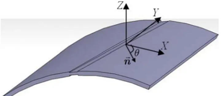
Assumptions related to the Bending–Stretching process The sheet is assumed to be initially flat, with X and Y the two in-plane principal directions and Z the through-thickness di- rection, as illustrated in Fig. 1. It should be understood that the X-Y-Z coordinate system represents a material coordinate frame, which will rotate as material deforms. The following assumptions and choices are made in the development of this modified M–K approach:
– The sheet is first subjected to a bending moment M ap-plied in Y-direction, resulting in the sheet being curved along X-direction, with a uniform curvature R. Hence, there is a single curvature along X-direction, while the sheet remains straight along the Y-direction (see Fig. 1). – The neutral axis is assumed to remain located at the
mid-layer of the sheet metal during deformation.
– The studied sheet is assumed to be wide enough (along the Y-direction) relative to its thickness. Consequently, the strain component εyy can be neglected during the bending process.
– The sheet is initially submitted to a heterogeneous distri-bution of out-of-plane stress through its thickness. This out-of-plane stress distribution is assumed to take a con-stant value during the deformation for each surface locat-ε
˙ ¼ λ˙
∂σ ; ð1Þ ed at a given distance from the mid-layer of the sheet. where λ˙ is the plastic multiplier (equal here to the von Mises
equivalent strain rate ˙εeq ), σ is the Cauchy stress tensor, and
σeq is the von Mises equivalent stress. By using the definition of σeq, the rigid–plastic constitutive law can be derived from Eq. (1)
– After the bending stage, an axial major strain along X and a minor strain along Y are then applied to the sheet under a constant strain-path ratio ρ, while the bending radius is kept constant equal to R.
ε ˙ ¼ 3˙εeq 2 σeq S⇔S ¼ 2 σeq 3˙εeqε ˙ ; ð2Þ
Modif ied M–K equations where S is the deviatoric part of σ. These two tensors are
linked by the following relation:
The M–K approach is based on the assumption of the preex- istence of an initial geometric imperfection in the form of a
ST H ST ST ST xx !n i 1− σ i 1− σ ( = B B H 2
The stretching part ε˙ H is assumed to be uniform over the thickness of the sheet and is given by the following expres- sion: ε ˙ ST ¼ H εST xx 0 ! H ; ð8Þ 0 ρ˙εST xx
where the strain-path ratio ρ is varied in the range −1/2 ≤ ρ ≤ 1 to span the complete FLD.
Fig. 1 Initial imperfection approach for the sheet metal
The stretching part of the strain rate in the band ε˙ B is related to that outside the band ε˙ H by the following kinematic band across the thickness of the sheet, as illustrated in Fig. 1. compatibility condition:
T\
This band is defined by its normal unit vector !n . The angle ε ̇B
H (→̇ ! (→̇
between vector !n and the major strain direction X is denoted θ. The initial thickness of the band (resp. zone outside the
ST ¼ ε ̇ST þ ð1=2Þ c ⊗ n þ c ⊗!n ; ð9Þ
band) is equal to hB (resp. hH ). where !c˙ is the jump vector. Vectors !c˙ and !n are assumed to
0 0 be uniform over the thickness of the sheet.
The sheet illustrated in Fig. 1 is subjected to biaxial stretching in the X and Y directions. Additionally, a non-zero principal stress σzz acts in the out-of-plane direction (i.e., in
The evolution of the band orientation θ is given by the following relation:
the Z-direction). The distribution of this stress component is
assumed to be homogeneous through the plane of the sheet θ ¼ arctan l
tanðθ0Þ expð1−ρÞ εH
l
; ð10Þ
(i.e., σzz is independent of x and y coordinates), but heteroge- neous over the thickness of the sheet. The value of σzz is taken constant for each surface located at a given distance from the mid-layer of the sheet. For example, σzz is equal to −α at the
where θ0 is the initial value of the band orientation.
The global equilibrium equation across the band can be expressed as follows:
inner surface of the sheet (where α is a non-negative pressure, constant during the deformation), while it is equal to 0 at the
( hH =2
H
∫−hH =2σ dz
hB 2
: ¼ ∫−hB =2σ dz :!n ; ð11Þ
outer surface. Also, σzz is assumed to evolve linearly, as a function of the z coordinate, between the two external surfaces of the sheet. The distribution and the magnitude of σzz are
where hH and hB are the current thicknesses of the sheet out-side and in the band zone, respectively. These thicknesses are expressed as functions of their initial values hH B
assumed to be the same both in the homogeneous zone and the components of ε˙ H ˙ B 0 and h0 and of
in the band. As a consequence of the assumptions made in BAssumptions related to the Bending– Stretching process
hH ¼ hH
ST and εST
−ðεST xxþεST yyÞ ¼ h e−ðεST xx εST yyÞ
section^ and the spatial distribution of σzz, it can be shown H H
0 e ; h
B B þ B
0 : ð12Þ
that the different mechanical variables (strain, stress…) are independent of the x and y coordinates, both inside and outside the band. These mechanical variables only depend on the z coordinate. Under the incompressibility condition, it is more convenient to rewrite in what follows the governing equations in the form of an in-plane formulation (i.e., in the plane (X Y)).
It appears to be difficult to determine analytical expressions providing exact values for the two integrals introduced in Eq. (11). Therefore, these integrals are rather numerically approxi- mated by the trapezoidal method, after a geometric discretization of the sheet thickness is performed
The total strain ε is additively decomposed into a bending h =2
∫ z
\
þ i iþ1 i
part εBE and a stretching part εST
H −hH =2σ i¼Ν p −1 zH H H H dz ¼ ∑ i¼1 13Þ hB =2 B i¼Ν p −1 zB B B B ð ε ¼ εBE þ εST: ð6Þ ∫−hB =2σ dz ¼ ∑ i¼1 z \ þ i iþ1 i ; 2 The above decomposition is valid both inside and outside
the band.
Also, the bending part εBE of the deformation tensor has
where Np is the number of integration points used in the numer- ical quadrature, which is assumed, for convenience, to be the
same for both zones. In Eq. (12), zH (resp. zB ) represents the i i
current position of the ith integration point through the thickness
H H
Lnð1 þ z=RÞ 0 \ in the zone outside the band (resp. in the band). Hence, z1 , zN p , εBE ¼
0 0 : ð7Þ zB B H H B B
i 0 Δε =Δε 0 x x x ST zz x x B
Furthermore, zH (resp. zB ) is related to its initial value zH integration of the governing equations section^ to
inte-(resp. zB
i i
) by
i 0
grate the governing equations detailed in BGoverning equations section^. The application of this incremental zH H −ðεH þεH Þ ; zB B −ðεB ε Þ: 14 integration scheme is stopped when the following
criteri-i ¼ zi 0 e ST xx ST yy i ¼ zi 0 e ST xxþ ST yy ð Þ on is satisfied:
Algorithmic aspects
Bending process B ST zz H ST zz≥ 10: ð17ÞBefore the stretching loading is applied, the sheet metal is first bent by applying a bending moment M. During this bending stage, the curvature radius decreases from +∞ (which corre-sponds to a flat sheet) to a finite value R. This bending is moderate compared to stretching (typically the ratio hH=R does not exceed 0.2). Therefore, it is legitimate to consider the distance z of any integration point to the neutral axis as a constant value, which is taken equal to its initial value z0. At the end of this bending process, the equivalent strains corre- sponding to the different points located inside and outside the
The strain component εH , thus obtained once the criterion
(17) is satisfied, is considered as being the critical strain ε*
corresponding to the initial band inclination θ0 and strain-path ratio ρ. The factor 10 in Eq. (17) is rather arbitrary and any other relatively large positive value can be used without loss of accuracy. Indeed, the impact of this value on the predicted critical strain is minimal, since the absolute value of the band thickness strain rate ˙εB increases very rapidly towards in- finity at incipient necking.
The smallest critical strain ε* , over all initial angles θ
0, and the corresponding current angle, define the necking limit band are computed strain εL and the necking band orientation, respectively, for
8 2
εH H
the current strain-path ratio ρ. ∀i ¼ 1; …; Ν p : <> eq i ¼ pffi3ffi Ln 1 þ zi
0=R 2 ð15Þ The above-developed algorithm and the associated
algo-rithmic aspects have been implemented in a standalone code
εB B
:> eq i ¼ pffi
3ffi Ln 1 þ zi 0=R :
Simultaneously to this bending loading, a normal stress, which is constant during the loading and heterogeneous, is applied on both the safe zone and the band. As previously discussed, this normal stress is linearly distributed through the thickness of the sheet, as defined by the following rela-tions:
developed using the multi-paradigm numerical computing en-vironment Mathematica. This implementation is carried out independently of any FE code. The input data for this code are all parameters related to the material (isotropic hardening), geometry (thickness of the sheet and curvature radius), me- chanical state (amount and distribution of the normal stress) and numerical choices (number and position of the different integration points). On the other hand, the output results are
the limit strain εL and the necking band orientation
corre-σH α H α sponding to the strain-path ratio ρ.
∀i ¼ 1; …; N p : zz i ¼
hH zi − 2 ð16Þ σB α B α
zz i ¼ hB zi − 2 :
Algorithm for the FLD prediction
The general algorithm developed for the FLD prediction is based on the following three nested loops:
• For each strain-path ratio ρ ranging from −1/2 to 1 (with increments Δρ of 0.1).
– For each initial band orientation θ0, spanning the admissi-ble range of inclination angles (i.e., between 0° and 90°), at user-defined intervals (here, we take intervals of 1°). For each time interval [t0, t0+Δt], apply the implicit in- cremental algorithm described in BIncremental
Incremental integration of the governing equations The main purpose of this incremental algorithm is to integrate the equations governing the modified M–K approach over a typical time increment [t0, t0 + Δt]. In this aim, we assume that, at each integration point located in the zone outside the band or in the band, the following quantities are known at time t0:
– The coordinate through the thickness direction z (see Eq.
14).
– The equivalent strain εeq (see Eq. 15) – The normal stress σzz (see Eq. 16).
In order to simplify notations, the argument t0+Δt will be omitted hereinafter, with the implied understanding that the
ST zz ST B 0 ρ Δε ST Δε Δε ¼ Δε e ST xx ST zz ST zz B BE BE i i H ST zz Δε ST xx BE i ST xx i eq
corresponding quantity is evaluated at t0 + Δt, unless other- wise indicated.
The increment over [t0, t0 + Δt] of the strain tensors εH and εB
at the different integration points located outside and in the The increment ΔεB is chosen as loading parameter over band zone is finally determined as follows:
[t0, t0 + Δt]. It is typically set to −0.001. ΔεH ΔεH ΔεH
The increment ΔεH is derived from the integration of Eq. (8): ∀i ¼ 1; …; Ν p : ΔεBi ¼ ST B þ BE i ; ð26Þ i ¼ ΔεST þ ΔεBE i
H \
ΔεH Δε
ST xx 0
¼
: ð18Þ where the expressions of ΔεH , ΔεH , ΔεB , and ΔεB are
ST H
ST xx ST BE i ST BE i
On the other hand, the components of the increment ΔεB
are derived from the integration of Eq. (9)
given by Eqs. (18), (19), (22), and (25), respectively. Accordingly, for a given strain-path ratio ρ, the strain incre-ments ΔεH and ΔεB are functions of three scalar unknowns:
i i ΔεB ¼ ΔεH þ Δc 1 n1 H ST xx, Δc1 and Δc2. ST xx B ST xy ΔεB ST xx B ST yx ¼ ρ ΔεH ¼ ð1=2Þ ðΔc1 n2 þ Δc2 n1Þ þ Δc2 n2: ð19Þ
The expression of the deviatoric stress S at the different integration points inside and outside the band is derived from Eq. (5)
ST yy ST xx
2 Κ εn
It is noteworthy that Eq. (19) has been derived from Eq. (9) by implicitly assuming that, all along the time increment, the
S ¼
3 Δε Δε: ð27Þ
components of vector !n keep their initial values at t0. Furt her mo re, Eq . ( 19 ) in c o nj unctio n w it h the incompressibility condition leads to the following relation:
The Cauchy stress tensor σ can be expressed as follows: 0 σxx 0 0 1 ð1 þ ρÞ ΔεH þ Δc1 n1 þ Δc2 n2 ¼ −ΔεB : ð20Þ σ ¼ @ 0 σyy 0 0 0 σzz A: ð28Þ
In the band, the position of the different integration points at t0 + Δt can be easily expressed in terms of ΔεB
Tensor σ is related to its deviatoric part S by
S ¼ σ−ð1=3Þ trðσÞ I2: ð29Þ
∀i ¼ 1; …; N p : zB ¼ zBðt0Þ eΔεST zz : ð21Þ Therefore, the components of tensor S are given by the
i i
By using Eqs. (7) and (21), the increment of εB over [t
0, following relations: t0 + Δt], for the different integration points within the band,
can be expressed as Sxx ¼ 2 σxx−σyy−σzz 3 2 σyy−σxx−σzz 0 ∀i ¼ 1; …; Ν p : ΔεB ¼ @ Ln R þ zB \ R þ zBðt 0Þ 1 0 A:ð22Þ Syy ¼ 3 2 σ zz − σ xx − σ yy ð30Þ 0 i 0 Szz ¼ 3 :
The position at t0 + Δt of the integration points located outside the band can be determined by the following equation: ∀i ¼ 1; …; Ν p : zH ¼ zHðt0Þ eΔεST zz ; ð23Þ
By inverting the above relations, one can obtain the expres- sions of σxx and σyy as functions of Sxx, Syy and σzz
σxx ¼ 2 Sxx þ Syy þ σzz ; σyy ¼ 2 Syy þ Sxx þ σzz: ð31Þ i i
where ΔεH condition
is determined by applying the incompressibility The distribution of the normal stress σzz over the thickness of the sheet is given by Eq. (16).
Combining Eqs. (3), (27) and (31), one can easily derive
H
ST zz¼ −ð1 þ ρÞ Δε
H : ð24Þ the expression of the Cauchy stress tensor σ at the different integration points over the thickness of the sheet.
The increment of εH over [t
0, t0 + Δt] for the different Once determined, the expression for σ is then inserted in integration points located outside the band is determined by
a relation very similar to Eq. (22)
the approximation (13), which in turn is inserted in the equi-librium Eq. (11). Analyzing the previous developments, Eq. (11) may be regarded as a system of two equations with three 0
∀i ¼ 1; …; Ν p : ΔεH ¼ Ln R þ z
H \ 0 1
: ð25Þ scalar unknowns: ΔεH , Δc1and Δc2. By considering Eq.
BE i @ R þ zHðt
0Þ A
ST zz and ε ST xx ST xx ST zz=Δε ST zz=Δε x x ST xx x ST zz=Δε ST ST xx x
should be solved iteratively by using the Newton–Raphson
a
method in order to determine the above-mentioned scalar un-knowns. Ultimately, the determination of these unknowns
al-lows computing the different quantities at t0 + Δt: namely, the 12 distance of the different integration points to the neutral axis of
the sheet, the distribution of the equivalent strain through the
9
thickness in both zones, and the band orientation. In particular,
R mm R 10 mm R 100 mm Flat sheet
the values of the strain components ΔεH HST xx (the latter being equal to εH ðt
0Þ þ ΔεH ) are of special inter- 6
est; the former being required for the application of the
neck-ing criterion (17), while the latter is needed in the algorithm of 3 BAlgorithm for the FLD prediction section^.
Prediction results
The current section is divided into four subsections:
• The material and geometric data are briefly presented in the first subsection.
• The effect of curvature on the enhancement of formability is demonstrated in the second subsection through several numerical simulations (under plane-stress assumption). • The third subsection is dedicated to the investigation of the
effect of normal stress on the formability of a flat sheet. • The combined effects of curvature and normal stress on
formability are depicted in the fourth subsection.
0 0.00 0.03 0.06 0.09 0.12
b
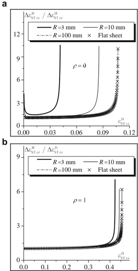
9 R mm R 10 mm R 100 mm Flat sheet 6 3 0 0.0 0.1 0.2 0.3 0.4Fig. 2 Illustration of the onset of localized necking: evolution of the ratio Material and geometric data
A DP600 sheet steel with the hardening parameters K = 945 MPa and n = 0.16 is used in the following simulations. The initial thicknesses hH and hB are set to 1 mm and
ΔεB H H
ST zz=ΔεST zz as a function of εST xx: (a) plane strain tensile state (ρ = 0); (b) equibiaxial tensile state (ρ = 1)
0 0 radius is almost the same as that corresponding to a flat sheet,
0.99 mm, respectively. The number of integration points Np is taken equal to 11.
as observed in Fig. 2.
Figure 3 depicts the evolution of the ratio ΔεB H ST zz
Effect of curvature
Figure 2 shows the evolution of the ratio ΔεB H ST zzas a
as a function of εH (the major deformation of the outer surface
of the sheet) for both cases of plane strain tensile state (ρ = 0) and equibiaxial tensile state (ρ = 1). It must be noted that the strain component εH is the strain that is actually measurable
function of εH for both cases of plane strain tensile state during the deformation. It is clearly shown from this figure (ρ = 0) and equibiaxial tensile state (ρ = 1). In this figure, three
bending radii are considered: R = 3 mm; R = 10 mm; R = 100 mm. The results corresponding to a classical flat sheet are also included in this figure. The occurrence of strain
local-that the limit strain εH decreases with the bending radius. This
means that bending tends to retard the occurrence of localized necking and, thus, to enhance formability, especially when the bending radius is small. The difference in the trends between ization is predicted when the ratio ΔεB H
ST zz exceeds Figs. 2 and 3 is due to the contribution of the bending part to
10, as stated by criterion (17). It is clear from this figure that the strain measure: only the stretching contribution εH xx has
the value of εH at the onset of strain localization increases been used in Fig. 2, while the total strain component εH is
with the bending radius R. For large values of the bending radius R (e.g., more than 100 mm), bending effect is very limited. In such conditions, the prediction with high bending
used in Fig. 3. As the bending strain component (which is equal to the difference between εH and εH ) significantly
xx ST xx
ST xx εL ST xx Δε =Δε xx ST zz=Δε x ST xx x ST xx S H
a
The effect of bending radius on the evolution of the stretching critical strain ε* , as a function of the initial bandorientation θ0, is investigated in Fig. 5 for the case of uniaxial tensile strain path. Note that the necking band is not perpen- dicular to the major strain direction, whatever the value of the bending radius R. Indeed, the stretching critical strain ε*
decreases with the initial band orientation θ0 until reaching its lowest value, which corresponds to the stretching limit strain
ST xx, and then it increases afterwards. This result is common
to all negative strain paths, as demonstrated in Fig. 6. However, for positive strain paths, the necking band is per- pendicular to the major strain direction. These observations are classical for flat sheets when bending effects are not con- sidered. Note that the effect of bending radius on the necking band orientation θ is not very significant, as shown in Fig. 6.
b
The results presented in Fig. 5 for the particular case ofuniaxiale tensile strain path are extended in Fig. 7 to the whole
a
Fig. 3 Illustration of the onset of localized necking: evolution of the ratio B
ST zz HST zzas a function of εH : (a) plane strain tensile state (ρ = 0); (b) equibiaxial tensile state (ρ = 1)
the opposite trends observed between Fig. 2 and Fig. 3. It must
be noted that the evolution of the ratio ΔεB ST zz is
b
presented in Fig. 3 during the stretching phase only (i.e., the bending stage is not shown in this figure). This fact explains why the initial value of εH (which correspond to the onset of
the stretching phase) is not always equal to zero (especially for small to moderate bending radii, see Fig. 3 (a)).
To further investigate the effect of curvature on the onset of strain localization, the stretching limit strain εL (the
stretching strain determined at the onset of plastic strain local-ization) and the total limit strain εL (the sum of the stretching
strain and the bending strain, as predicted at the beginning of localized necking) are plotted as functions of the inverse of the bending radius R in Fig. 4 (a) and Fig. 4 (b), respectively. In both figures, four representative strain paths are considered: ρ = − 0.5; ρ = 0; ρ = 0.5; and ρ = 1. The results of Fig. 4 (a)
(resp. Fig. 4 (b)) confirm the observations displayed in Fig. 2 Fig. 4 Effect of curvature on the onset of localized necking: (a) Evolution of the stretching limit strain εL as a function of the ratio (resp. Fig. 3). 1/R; (b) Evolution of the total limit strain εL as a function of the ratio 1/R
ST xx
plotted in terms of the stretching strain components only, and the one represented in terms of the total strain compo- nents) coincide exactly when the curvature radius is taken very large (e.g., R = 100 mm, or a flat sheet).
Effect of normal stress
Fig. 5 Effect of the bending radius on the evolution of the stretching critical strain ε* as a function of the initial band orientation θ
0 for uniaxial tensile strain path
range of strain paths, where the effect of bending radius on the location and shape of FLDs is analyzed. In Fig. 7 (a), the major stretching limit strain (simply denoted εST xx) is plotted as a function of its minor counterpart εST yy. In Fig. 7 (b), however, the major total limit strain at the outer surface of the sheet (simply denoted εxx) is plotted as a function of its minor counterpart εyy. It should be noted that, as bending is not considered in the y-direction, εST yy is identically equal to εyy for the different strain paths. It appears from Fig. 7 (b) that the bending effect is more significant in the left-hand side of the FLD than in its right-hand side. The predictions reported in this figure confirm once again that the classical curvature has a beneficial effect on the formability of thin sheets. By compar- ing the results displayed in Fig. 7 (a) and Fig. 7 (b), one can easily observe that the two FLD representations (i.e., that
Fig. 6 Effect of the bending radius on the necking band orientation θ for negative values of the strain-path ratio ρ
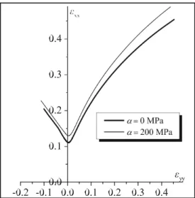
The effect of normal stress on the formability of a flat metal sheet is investigated in Fig. 8. The curvature effect is not considered in the results of Fig. 8, since the sheet is assumed to be flat. In this figure, two different values of maximal nor- mal pressure α are used: α = 0 MPa (which correspond to the traditional case of plane-stress state) and α = 200 MPa. When α is set to 0 MPa, the results displayed in Fig. 7 are naturally recovered. The results of Fig. 8 demonstrate that the applica- tion of compressive normal stresses on a sheet allows its form- ability to be enhanced, especially in the range of positive strain paths. These results are consistent with several earlier investi- gations (see, e.g., [10, 13, 14]).
a
b
Fig. 7 Effect of the bending radius on the location and the shape of FLDs: (a) FLDs only in terms of stretching strain components; (b) FLDs in terms of total strain components
and plane-stress state), for the prediction of formability of some parts and components involved in various industries may lead to inaccurate and inconsistent conclusions.
Concluding remarks
Fig. 8 Effect of normal stress on the location and the shape of FLDs
Combined effects of curvature and normal stress
The combined effects of bending and normal stress on the enhancement of formability are highlighted in Fig. 9. For in- stance, the limit strain for a plane strain tensile state is approx- imately equal to 0.2 when the curvature R and the maximal pressure α are set to 3 mm and 200 MPa, respectively. However, the limit strain for the same strain path is equal to only 0.1 when the sheet is taken to be flat and under plane- stress condition (i.e., the classical assumptions for the deter- mination of traditional FLDs). The results of this figure high- light the importance of considering the effects of both curva- ture and normal stress in the modeling and the prediction of the onset of localized necking. Indeed, the use of classical tools, which are developed under the traditional assumptions (i.e., homogeneity of the deformation through the thickness
Fig. 9 Combined effects of curvature and normal stress on the location and the shape of FLDs
A numerical tool has been developed in this paper for the prediction of localized necking in sheet metals undergoing combined bending–stretching loadings and submitted to out- of-plane compressive stresses. This model may be useful to help understand how the respective and combined effects of bending and normal stresses, which are commonly involved in forming processes, would affect sheet metal formability. Contrary to some existing models, where the effects of curva- ture and normal stress on formability are investigated sepa- rately, the current work allows the two effects to be taken into consideration within the same model. Furthermore, the pres- ent model is capable of considering a heterogeneous distribu- tion of normal stresses through the thickness of the sheet. In the current contribution, the mechanical behavior of the sheet metal has been described by the rigid–plastic flow theory, while localized necking prediction is based on the imperfec- tion approach. From the numerical predictions obtained by applying this tool, it is concluded that the addition of bending loading to traditional stretching and/or the consideration of out-of-plane compressive stresses allows significantly delaying the occurrence of localized necking and, thus, en- hancing the formability of the studied sheet. The use of the proposed tool, instead of traditional available tools based on the classical assumptions, is believed to provide more accurate predictions for the formability of a number of industrial parts and components.
It is also worth noting that the current work is a first step in a wider project, which aims to investigate the effects of bend- ing and normal stress on the formability of thin metal sheets. In future work, the developed numerical tool will be extended in order to take into account more advanced constitutive models, which would allow a better description of the me- chanical behavior of the studied materials. Such elaborate models will include the effects of elasticity, strain-rate sensi- tivity, plastic anisotropy and kinematic hardening. Besides, the compatibility condition given by Eq. (9) will be written in a local form, accounting for the heterogeneity of the jump vector through the thickness of the sheet. Indeed, in the current version of the model, the jump vector is assumed to be homo- geneous through the thickness and independent of the position of the integration points relative to the neutral axis of the sheet. The consideration of the heterogeneity of the jump vector would allow a more precise description of the bending– stretching process and thus a more accurate prediction of the forming limit diagrams.
Compliance with ethical standards
Conflict of interest The authors declare that they have no conflict of interest.
References
1. Keeler SP, Backofen WA (1963) Trans ASM 56:25 2. Goodwin GM (1968) Metallurgia Italiana 60:767 3. Marciniak Z, Kuczynski K (1967) Int J Mech Sci 9:609
4. Hutchinson JW, Neale KW, Koistinen DP, Wang NM (Eds.) (1978) Mechanics of Sheet Metal Forming. Plenum 127
5. Shi M, Gerdeen J (1991) J Mater Shap Technol 9:253
6. Sriram S, Yao H, Ramisetti N (2012) J Manuf Sci Eng 134:031003 7. He J, Xia ZC, Li S, Zeng D (2013) J Manuf Sci Eng 135:227 8. He J, Xia ZC, Zeng D, Li S (2013) J Eng Mat Tech 135:031009 9. Safdarian R (2015) Mech Res Commun 67:47
10. Gotoh M, Chung T, Iwata N (1995) JSME Int J Ser A 38:123 11. Swift H (1952) J Mech Phys Solids 1:1
12. Hill R (1952) J Mech Phys Solids 1:19
13. Allwood JM, Shouler DR (2009) Int J Plasticity 25:1207 14. Fatemi A, Dariani BM (2015) Int J Adv Manuf Tech 80:1497