HAL Id: tel-02880025
https://pastel.archives-ouvertes.fr/tel-02880025
Submitted on 24 Jun 2020
HAL is a multi-disciplinary open access archive for the deposit and dissemination of sci-entific research documents, whether they are pub-lished or not. The documents may come from teaching and research institutions in France or abroad, or from public or private research centers.
L’archive ouverte pluridisciplinaire HAL, est destinée au dépôt et à la diffusion de documents scientifiques de niveau recherche, publiés ou non, émanant des établissements d’enseignement et de recherche français ou étrangers, des laboratoires publics ou privés.
High frequency magnetic field-induced strain of
ferromagnetic shape memory alloys
Shaobin Zhang
To cite this version:
Shaobin Zhang. High frequency magnetic field-induced strain of ferromagnetic shape memory alloys. Mechanics of the solides [physics.class-ph]. Université Paris Saclay (COmUE), 2018. English. �NNT : 2018SACLY011�. �tel-02880025�
High Frequency Magnetic
Field-induced Strain of Ferromagnetic
Shape Memory Alloys
Thèse de doctorat de l'Université Paris-Saclay préparée à l'Ecole Nationale Supérieure de Techniques Avancées
École doctorale n°579 sciences mécaniques et énergétiques, matériaux et géosciences (SMEMAG) Spécialité de doctorat : Mécanique des solides
Thèse présentée et soutenue à Palaiseau, le 07 septembre 2018, par
M. Shaobin ZHANG
Composition du Jury : M. Etienne PATOOR
Professeur, Georgia Tech-Lorraine Président
M. Günay ANLAS
Professeur, Boğaziçi University Rapporteur
M. Mohamed HABOUSSI
Professeur, Université Paris 13 Rapporteur
M. Tarak BEN ZINEB
Professeur, Université de Lorraine Examinateur
M. Laurent DANIEL
Professeur, CentraleSupelec Examinateur
M. Olivier HUBERT
Professeur, ENS Paris-Saclay Examinateur
M. Yongjun HE
Maître de Conférences (HDR), ENSTA ParisTech Directeur de thèse
M. Ziad MOUMNI
Professeur, ENSTA ParisTech Co-Directeur de thèse
NNT : 2 0 1 8 S A CLY 0 1 1
T
HÈSE DE
D
OCTORAT
DE
L
’U
NIVERSITÉ
P
ARIS
-S
ACLAY
PRÉPARÉE À
L’ECOLE
NATIONALE
SUPÉRIEURE DE
TECHNIQUES
A
VANCÉESÉCOLE DOCTORALE N°579
Sciences mécaniques et énergétiques, matériaux et géosciences (SMEMaG)
Spécialité de doctorat : Mécanique des solides
Par
Shaobin ZHANG
High Frequency Magnetic Field-induced Strain of
Ferromagnetic Shape Memory Alloys
Thèse présentée et soutenue à Palaiseau, le 07 septembre 2018; Composition du Jury :
M. Etienne PATOOR Professeur, Georgia Tech-Lorraine Président
M. Günay ANLAS Professeur, Bo˘gaziçi University Rapporteur
M. Mohamed HABOUSSI Professeur, Université Paris 13 Rapporteur
M. Tarak BEN ZINEB Professeur, Université de Lorraine Examinateur
M. Laurent DANIEL Professeur, CentraleSupelec Examinateur
M. Olivier HUBERT Professeur, ENS Paris-Saclay Examinateur
M. Yongjun HE, Maître de Conférences (HDR), ENSTA ParisTech Directeur de thèse
Dedicated to my late grandfather
And my beloved family,
Acknowledgements
I would like to take this opportunity to sincerely express the gratitude to my supervisors, Dr. Yongjun He and Prof. Ziad Moumni for their guidance through these three years at ENSTA-ParisTech. Yongjun is always willing to spend his precious time discussing my ideas and works. His good tastes, keen senses and critical thinking to the scientific problems help me improve my work a lot. He is generous in sharing his personal research experience which inspire me to constantly exploring the unknown world with persistence. Ziad always concerns my research progress and help me overcome the difficulties. His encouragement and support give me confidence to step forward. Both supervisors have given me a great freedom to pursue the research in my own way, which helps me gain the ability of doing scientific research independently. I am very grateful for I have worked with Yongjun and Ziad.
Many thanks to all my thesis committee members, Prof. Anlas, Prof. Ben Zineb, Prof. Daniel, Prof. Haboussi, Prof. Hubert, Prof. Patoor, for their comments, fruitful discussions and useful suggestions.
I would also like to thank all my colleagues in our lab of Unité de Mécanique (UME). Particularly, Prof. Habibou Maitournam is acknowledged for his help and concern in my work. Lahcène Cherfa, Nicolas Baudet, Oana-Zenaida Pascan, Lin Zheng, Nicolas Thurieau, Quantin Pierron, Thierry Pichon and Alain Van Herpen are appreciated for their kind help on my experimental setup. All the following colleagues, Anne-Lise Gloanec, Fabien Szmytka, Kim Pham, Andres Leon Baldelli, Claude Stolz, Josiane Nguejio Nguimatsia, Xiaojun Gu, Jun Wang, Yinjun Jiang, Yahui Zhang, Marine Bayard
vi
and Masmoudi Moez are also acknowledged for the active research atmosphere.
My intership students, Amine Kirati, Ali Hamieh and Onjatiana Victorain Rako-toarivony from Ecole spéciale militaire de Saint-Cyr, Xianghe Jiang from Ecole Poly-technique, Amine Bettaieb, Marouan Ben Saada, Mourad Jouili and Majed Salhi from Tunisian Military Academy, and Jian Zhang from Polytech Paris-Sud should also be acknowledged for their help and discussions in my experiments.
Thanks to Yongjun, Lin, Xiaojun, Jun, Yinjun and Yahui for our beautiful memories and their delicious dishes, the flavor of hometown. Besides, special acknowledgement to Yahui Zhang, who has been my officemate in UME, schoolmate in Northwestern Polytechnic University (NPU) and classmate in high school. We have been growing up, learning and working together from 15 years old to the present and from Fengxiang (China) to Paris (France). I like to thank Yahui for all the funny and youthful moments and all the supports from him. They will be the most precious and greatest memories in my entire life.
This work was funded by China Scholarship Council (No. 201506280009). I am very appreciative of their financial support.
Finally, I would love to thank my family, my parents, grandparents and elder sisters for their unselfish love and support. As farmers in a developing country, they have sacrificed too much of their own personal lives to accomplish this impossible mission of supporting me to be a Doctor. The most special thanks to my wife Wenjun for her endless love and encouragement. She always gives me confidence to go forward, because I am sure that she will always stay with me for the rest of our life even if I lost the whole world.
Publications
Journals
Zhang, S., Chen, X., Moumni, Z., and He, Y. (2018). Thermal effects on high-frequency magnetic-field-induced martensite reorientation in ferromagnetic shape memory alloys: An experimental and theoretical investigation. International Journal of Plasticity, 108: 1–20.
Zhang, S., Chen, X., Moumni, Z., and He, Y. (2018). Coexistence and compatibility of martensite reorientation and phase transformation in high-frequency magnetic-field-induced deformation of Ni-Mn-Ga single crystal. International Journal of Plasticity, accepted, https://doi.org/10.1016/j.ijplas.2018.06.010
Zhang, S. and He, Y. (2018). Fatigue resistance of branching phase-transformation fronts in pseudoelastic NiTi polycrystalline strips. International Journal of Solids and Structures, 135: 233–244.
Proceeding
Zhang, S., Moumni, Z., and He, Y. (2018). Thermal effects on dynamic magnetic-field-induced martensite reorientation of single crystal Ni-Mn-Ga. In European Solid Mechanics Conference, Bologna, Italy.
Zhang, S. and He, Y. (2017). Domain interfaces and fatigue failure of NiTi poly-crystalline strips. In ECCOMAS Thematic Conference on Smart Structures and Materials (SMART 2017), Madrid, Spain.
Abstract
Ferromagnetic Shape Memory Alloys (FSMAs) have ability to provide large high-frequency reversible strain via magnetic field-induced martensite reorientation. But, the high-frequency frictional twin boundary motion of the martensite reorienta-tion can induce a rapid accumulareorienta-tion of dissipareorienta-tion heat and cause a significant temperature rise in the material, which poses instability problems about the dy-namic performance of FSMA. Particularly, the output strain amplitude would be reduced significantly when the temperature increases to be high enough to trigger the Martensite-Austenite phase transformation. However, such thermal effect on the dynamic responses of FSMA has not yet been investigated in literature where most existing dynamic experiments were performed only for a short-time period (a few seconds) to avoid the temperature variation. In this thesis, multi-scale ex-perimental and theoretical analyses of the long-time performance of FSMA under high-frequency magnetic actuation are performed. Systematic experiments of the long-time magnetic actuation (> 100 seconds) on a Ni-Mn-Ga single crystal bar are conducted at various levels of magnetic field frequency, initial compressive stress and ambient airflow (ambient heat-exchange efficiency) to investigate their influ-ences on the stable state of the high-frequency FSMA-actuator. A one-dimensional heat-transfer model is developed and the new experimental phenomena of the ther-mal effects are well understood. Based on the experimental results and theoretical analysis, critical conditions to achieve the large and stable output strain amplitude in the high-frequency actuation are derived. Moreover, to understand the
heat-x
exchange dependence of the output nominal-strain from a microscopic view, the local strain distribution/evolution and the associated transformation/reorientation among the different phases/variants during the high-frequency actuation under various heat-exchange efficiencies are demonstrated via the in-situ Digital Image Correlation observations. A novel mechanism is revealed: the temperature-driven phase boundary motion (phase transformation) and the magnetic field-driven twin boundary motion (martensite reorientation) can be activated at the same time un-der the magneto-thermal-mechanical actuation (i.e., the high-frequency magnetic field, the mechanical spring force and the varying ambient airflow) as the material can self-organize its volume fractions of the different phases/variants to satisfy all the thermo-magneto-mechanical boundary conditions. Further, the self-organized morphology/pattern composed of various variants and phases during cyclic defor-mation (with the moving habit plane and twin boundaries) can be explained by microstructure compatibility analyses.
Keywords: Ferromagnetic shape memory alloy, high-frequency strain, magnetic field-induced martensite reorientation, temperature-induced phase transformation, microstructure compatibility, thermo-magneto-mechanical coupling.
Résumé
Les alliages à mémoire de forme ferromagnétique (FSMAs) possèdent la capacité d’accommoder une large déformation réversible à haute fréquence à l’aide d’une réorientation de la martensite induite par un champ magnétique. Cependant, cette réorientation à haute fréquence induit un frottement au niveau des interfaces entre les variantes de martensite provoquant une dissipation et par suite une élévation significative de la température dans le matériau, ce qui pose des problèmes d’in-stabilité nuisant à la performance du comportement dynamique des FSMAs. En particulier, l’amplitude de la déformation induite par le champ magnétique est ré-duite de façon significative lorsque l’augmentation de la température est suffisante pour déclencher la transformation de phase martensite-austénite. Un tel effet ther-mique sur les réponses dynather-miques de FSMA n’a pas encore été étudié dans la littérature où la plupart des expériences dynamiques existantes ont été réalisées sur une courte période de temps (quelques secondes) afin d’éviter la variation de la température. Le but de cette thèse est l’analyse et la modélisation de ce phé-nomène. Pour ce faire, des analyses expérimentales et théoriques multi-échelles des performances des FSMAs soumis à un champ magnétique de longue durée et à haute fréquence sont réalisées. Tout d’abord, des expériences systématiques d’actionnement magnétique de longue durée (> 100 secondes) sur une éprouvette en monocristal Ni-Mn-Ga sont effectuées à différents niveaux de la fréquence du champ magnétique, de la contrainte de compression initiale et du flux d’air ambiant (échange de chaleur) afin d’étudier leur influence sur la réponse des FSMAs. Par
xii
ailleurs, un modèle unidimensionnel de transfert de chaleur a été est développé permettant d’interpréter les nouveaux phénomènes liés aux effets thermiques mises en lumière expérimentalement. Ainsi, les conditions nécessaires à l’obtention d’une réponse dynamique stable ont été déduites. De plus, afin de comprendre la dépen-dance de la déformation nominale induite par le champ magnétique par rapport aux échanges thermiques à partir d’une analyse microscopique, la distribution/évolution de la déformation locale ainsi que la transformation/réorientation associée parmi les différentes phases/variantes au cours de l’actionnement à haute fréquence sous divers conditions d’échange de chaleur sont analysées via des observations in-situ à l’aide la corrélation d’images numériques (DIC). Un nouveau mécanisme est ainsi révélé : le mouvement des interphases induit par la variation de température (transformation de phase) et le mouvement des variantes de martensite induit par le champ magnétique (réorientation de martensite) peuvent être activés simultanément, sous l’actionnement magnéto-thermique-mécanique (i.e, le champ magnétique à haute fréquence, la force de ressort mécanique et le flux d’air ambiant) dans la mesure où le matériau peut auto-organiser les fractions volumiques des différentes phases/variantes afin de satisfaire toutes les conditions aux limites thermo-magnéto-mécaniques. En outre, la morphologie des bandes de déformations et des différentes phases/variantes auto-organisées est révélée et expliquée à l’échelle microscopique à l’aide des conditions de compatibilité géométrique.
Mots-clés : alliage à mémoire de forme ferromagnétique, déformation à haute fréquence, réorientation de la martensite induite par un champ magnétique, trans-formation de phase induite par la température, compatibilité de la microstructure, couplage thermo-magnéto-mécanique.
Contents
List of Figures xv
List of Tables xxi
1 Introduction 1
1.1 Overview of ferromagnetic shape memory alloys . . . 1
1.1.1 Development of ferromagnetic shape memory alloys . . . 1
1.1.2 Material properties of FSMA . . . 3
1.2 Motivations and objectives . . . 13
2 Experimental setup 17 2.1 Electromagnetic actuation and data acquisition system . . . 17
2.2 Ambient controlling during the test . . . 21
2.3 Optical observation on the specimen surface . . . 22
3 Thermal effects on high-frequency magnetic field-induced martensite reo-rientation 25 3.1 Introduction . . . 27
3.2 Experimental setup and testing procedures . . . 32
3.2.1 Material properties and experimental setup . . . 32
xiv Contents
3.3 Experimental results . . . 35
3.3.1 Effect of long-time actuation . . . 36
3.3.2 Effect of the ambient heat exchange . . . 45
3.4 Theoretical study on the effect of ambient heat exchange . . . 50
3.4.1 Non-monotonic dependence of stable strain amplitude on am-bient airflow . . . 50
3.4.2 Optimal conditions to achieve large stable strain amplitude . . 65
3.5 Summary and conclusions . . . 70
4 Coexistence and compatibility of martensite reorientation and phase trans-formation 73 4.1 Introduction . . . 74
4.2 Material properties and experimental setup . . . 78
4.3 Local strain evolution under high-frequency magnetic loading . . . . 80
4.4 Compatibility analysis and discussions . . . 88
4.5 Summary and conclusions . . . 101
5 Conclusions and perspectives 103 5.1 Conclusions . . . 103
5.2 Perspectives . . . 106
List of Figures
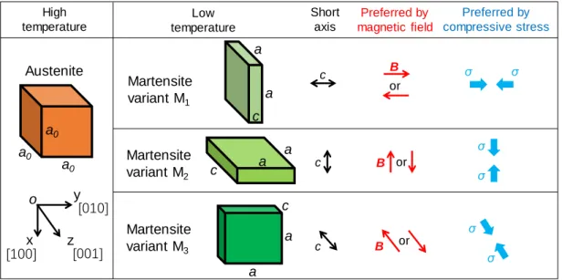
1.1 Schematic of lattice structures of Ni2MnGa (the difference between
aand c is exaggeratedly shown here) and the energetically preferred directions of the short axis c. . . 4
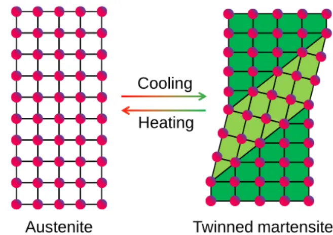
1.2 Schematics of (a) phase transformation and (b) martensite reorientation. 5
1.3 Schematics of shape memory effect and pseudoelasticity. . . 7
1.4 Schematic of magnetic field-induced martensite reorientation. . . 8
1.5 Schematic of magneto-mechanical loading-induced reversible marten-site reorientation. . . 11
2.1 (a) Schematic of actuation system to achieve high-frequency cyclic martensite reorientation, where the fixed parts (immobile components) during the dynamic actuation are in black, the moving parts (the spring and the upper sample holder) are in blue and the measuring sensors are in red. (b) Schematic of the martensite reorientation between the stress-preferred martensite variant (M1) and the magnetic-field-stress-preferred martensite variant (M2) in Ni-Mn-Ga specimen under the magneto-mechanical actuation. Approximated tetragonal martensite variant of one short axis (c-axis) and two long axes (a-axis) are adopted and the difference between a and c is shown exaggeratedly here. (c) Photo of the experimental setup for high-frequency magnetic actuation. . . 19
xvi List of Figures
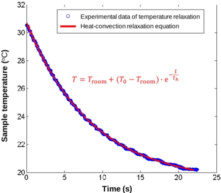
2.3 Temperature relaxation of Ni-Mn-Ga single crystal sample (2 × 3 × 15 mm) under the ambient airflow of 15 m/s. The fitted characteristic
heat-relaxation time this 8.8 s. . . 21
2.4 Schematic of the optical imaging method during high-frequency defor-mation. . . 23
3.1 DSC curves of the single-crystal Ni-Mn-Ga at the heating/cooling rate of 0.5◦C/min. . . 33 3.2 Typical responses of strain, stress and temperature of Ni-Mn-Ga
speci-men under long-time actuation (> 100 s) at the strain frequency fstr ain
= 180 Hz ( fmag= 90 Hz ) : (a) full-time responses, (b) magnified view
of the responses before strain drop at t ≈ 8 s and (c) stable state after the strain drop at t ≈ 100 s. (d) and (e) are the local-strain fields at the maximum nominal strain εmax and the minimum one εmin for the
two typical instants (before and after the strain drop) corresponding to the nominal behaviors shown in (b) and (c), respectively ; the strain profiles along the centerline of the specimen are plotted in terms of εy y-centerline by red lines. . . 38
3.3 Typical responses of the Ni-Mn-Ga specimen under the same initial compressive stress σini = 0.4 MPa with different frequency : (a) fstr ain
= 140 Hz ( fmag= 70 Hz ) and (b) fstr ain= 220 Hz ( fmag= 110 Hz ). . 40
3.4 Typical responses of Ni-Mn-Ga under the same frequency fstr ain= 180
Hz ( fmag= 90 Hz ) with different initial compressive stress : (a) σini =
0.2 MPa and (b) σini = 1.0 MPa. . . 41
3.5 The frequency-dependent stable and unstable strain amplitudes of the tests with the initial compressive stress σini = 0.4 MPa in still air.
∆εunstableand ∆εstablerepresent the strain amplitudes of the short-time
actuation (before strain drop) and the long-time actuation (after strain drop), respectively. The dashed lines are for guiding eyes. . . 43
List of Figures xvii
3.6 Stable temperatures Tstableof all tests conducted in still air with different
loading conditions (different strain frequencies and initial compressive stresses). The cases with strain drop are marked by the red dashed rectangle. . . 44
3.7 The responses of the tests at different levels of ambient airflow velocity : (a) ∼ (f) are respectively for the air velocity Vair = 60 m/s (th= 2.2 s),
35 m/s (th= 4.2 s), 15 m/s (th= 8.8 s), 8 m/s (th= 14.0 s), 3 m/s (th=
22.2 s) and 0 m/s (th= 68.9 s). All the tests are conducted at the same
magneto-mechanical loading conditions of fstr ain= 180 Hz ( fmag= 90
Hz) and σini = 0.4 MPa. . . 47
3.8 Airflow-dependence (th-dependence) of the stable strain amplitude
∆εstableand the stable temperature Tstable for all the tests with ambient
airflow of different velocities for the two typical loading frequencies : (a) fstr ain= 180 Hz and (b) fstr ain= 220 Hz. . . 49
3.9 One-dimensional heat-transfer model . . . 51
3.10 Typical tests to compare the temperature rises induced by the martensite-reorientation dissipation and the eddy current at the strain frequency
fstr ain = 180 Hz, with the different initial compressive stresses : (a) 0.4
MPa and (b) 4.0 MPa. . . 53
3.11 The temperature rise due to eddy current after the actuation of 100 s at different strain frequencies fstr ain are shown in (a) and the
correspon-ding heat generation rate is shown in (b). . . 54
3.12 Comparison of the temperature rise between Eq. (3.5) and the experi-mental data from the test of fstr ain = 180 Hz, σini = 0.4 MPa and Vair =
15m/s (th= 8.8s), whose responses of the strain and the stress can be
xviii List of Figures
3.13 The temperature dependence of twinning stress for the twin boundary motion during the magneto-mechanically driven martensite reorienta-tion. The two shaded regions represent the temperature dependence of the twinning stresses of the Type I and Type II twin boundaries, respectively, reported in (Heczko and Straka, 2003; Soroka et al., 2018; Sozinov et al., 2017; Straka et al., 2012; Zreihan et al., 2015). The thick blue and thin red lines (determined by Eq. (3.8) with ν = 0.65 and 0.42 respectively) represent the temperature dependences of the effective twinning stress of the mixed Type I and Type II twin boundaries in the dynamic actuation of fstr ain= 180 Hz and fstr ain = 220 Hz, respectively. 56
3.14 Comparison between the experiments (from the tests without strain drop (th < t∗h) in Fig. 3.8) and the model (Eq. ((3.9)b) and Eq. (3.10)
with and without considering eddy-current effect respectively) to esti-mate the contribution fraction (ν) of Type I twin boundary during the dynamic martensite reorientation process. (a) and (b) are respectively the dependence of stable strain amplitude ∆εstable on (Tstable− As) and
th at fstain = 180 Hz ; (c) and (d) are respectively the dependence of
stable strain amplitude ∆εstable on (Tstable− As) and that fstain = 220
Hz. The relations between (Tstable− As) and thare plotted in the insets
of (a) and (c). . . 59
3.15 The comparison between the theoretical model (Eq. (3.11)) and the experimental data for the tests at fstr ain = 180 Hz (a) and 220 Hz (b).
(c) The comparison between the normalized model (Eq. (3.13)) and the normalized experimental data of fstr ain = 180 and 220 Hz in terms of
∆ε¯stable and ¯tM R. . . 64
3.16 Contours of the output strain amplitude ∆ε at various frequencies and initial compressive stresses during the short-time actuation (a) and the long-time actuation (b). The data are from Table 3.1 and all the tests are conducted in the still air. . . 67
3.17 Oscillation phenomenon observed in the tests at the low initial com-pressive stress σini = 0.1 MPa : the strain amplitude ∆ε and the stress
List of Figures xix
4.1 (a) The global responses of FSMA-actuator under the same magnetic loading (the cyclic magnetic field between ±0.78 Tesla) but the chan-ging airflow velocity (Vair = 0 m/s ∼ 16 m/s). (b) The zoomed nominal
strain curves, the DIC local strain maps and the corresponding local strain profiles (the red and black lines represent the local strains at the maximum and minimum nominal strain states respectively) along the centerline at the typical time slots marked in (a). . . 81
4.2 DIC local strain evolutions in a typical cycle of the martensite reorienta-tion process before the occurrence of the strain drop phenomenon (pure martensite phase) at the time slot t1. . . 84
4.3 DIC local strain evolutions in a typical cycle of the martensite reo-rientation process with the existence of the non-active A-phase (the green region of A-phase (at lower right corner in each DIC map) has a constant local strain around 4%) at the time slot t6. . . 87
4.4 Twin boundaries of the tetragonal martensite variants of Ni-Mn-Ga. The x-y plane (the experimentally observed surface) is shown in color in each 3D schematic, where different colors represent different variants. 91
4.5 Theoretical predictions of all the possible patterns of A-M interface and martensite fine-twins (projections on x-y plane). The patterns in (a) and (b) are formed by fine twins of M1:M2, (c) and (d) are formed by fine
twins of M1:M3, (e) and (f) are formed by fine twins of M2:M3. . . . 95
4.6 The 3D and unfolded schematics and of the compatible microstructures with the coexistence of non-active austenite zone, buffering needle zone and active martensite zone in (a) ∼ (c) ; (d) The optical observation of the needle fine-twins jointly generated with A-M interface in a quasi-static thermo-mechanical test. . . 97
xx List of Figures
4.7 Schematic of the martensite reorientation (with twin boundary motion) between M1and M2driven by cyclic magneto-mechanical loading (see
the vertical evolution, marked by vertical dashed double-headed arrows) and the phase transformation (with A-M phase boundary motion) driven by changing heat-exchange efficiency (see the horizontal evolution from (a) to (d)). The buffering-zone can be compatible with both the austenite phase and martensite phase (no matter single variant or twins of M1and
List of Tables
3.1 The strain amplitudes of all the tests in the still air ambient at different strain frequencies and initial compressive stresses. The strain amplitudes appearing during the short-time actuation (before the strain drop) are highlighted in red. . . 42
4.1 Theoretical prediction on the compatible interfaces between the auste-nite phase and the martensite twins M1:M2. . . 93
4.2 Theoretical prediction on the compatible interfaces between the auste-nite phase and the martensite twins, whose schematic microstructure patterns are given in Fig. 4.5. . . 94
Chapter 1
Introduction
1.1
Overview of ferromagnetic shape memory alloys
1.1.1
Development of ferromagnetic shape memory alloys
Smart materials, called also active materials, can have one or more properties responding
to external fields such as mechanical, thermal, light, magnetic, electric field, et al. Some
traditional well-known smart materials, such as piezoelectric material, magnetostrictive
material and shape memory alloys (SMAs), have been investigated comprehensively
and well integrated into engineering applications. Generally, piezoelectric (e.g., PZT
Ceramic) and magnetostrictive materials (e.g., Terfenol-D) can function at high
frequen-cies (> 10 kHz) and has excellent stability. However, their maximum strains are quite
small (<0.2%) which seriously limits their applications. On the contrary, SMAs (e.g.,
the most popular one, NiTi) have ability to output/afford a large reversible strain (up
to 10%) while the operating frequency is quite limited (< 1 Hz). The high working
2 Introduction
class of smart materials, namely Ferromagnetic Shape Memory Alloys (FSMAs, e.g.,
Ni2MnGa), was developed in 1990s (Webster et al., 1984; Martynov and Kokorin, 1992).
Since Ullakko et al. first reported a 0.2% Magnetic Field-Induced Strain (MFIS) in
1996 (Ullakko et al., 1996) and Murray et al. extended the MFIS to 6% in 2000 (Murray
et al., 2000) in Ni2MnGa single crystals, FSMAs have attracted great research interest
(Karaca et al., 2007, 2009, 2006; Heczko et al., 2002; Henry et al., 2002; Heczko et al.,
2013; Straka et al., 2011b; Chmielus et al., 2008; Chulist et al., 2013; Pinneker et al.,
2014; Li et al., 2014; James and Wuttig, 1998) as they have potential ability to provide
large strain (up to 10%, comparable with that of traditional SMAs) at a high operating
frequency (up to 1 kHz), which gives FSMAs great advantages over other kinds of the
smart materials.
Nevertheless, it should be noted that up to now the large reversible strain can only
be obtained in single crystals of FSMA materials, which are very brittle and quite
expensive. These drawbacks pose difficulties for machining and applications of FSMAs,
which encourages some researchers to develop polycrystalline FSMAs (Gaitzsch et al.,
2007; Chulist et al., 2014; Liu et al., 2015; Huang et al., 2014; Li et al., 2017; Qian
et al., 2013). But so far a large reversible strain has not been achieved in polycrystalline
FSMAs. Therefore, now the single crystal FSMAs are still the research emphasis
for improving its material properties and make it suitable for the various promising
applications. In the next section, its crystal structure and properties are introduced in
1.1 Overview of ferromagnetic shape memory alloys 3
1.1.2
Material properties of FSMA
Magnetic field-induced strain can be achieved in various alloys such as Ni-based
(Ni-Mn-Ga, Ni-Mn-Al, Ni-Mn-In, Ni-Mn-Sn, Ni-Mn-Sb, Ni-Fe-Ga) (Lai et al., 2008; Henry
et al., 2002; Techapiesancharoenkij et al., 2009; Karaca et al., 2009; Neudert et al.,
2012; Sutou et al., 2004), Co-based (Co-Ni, Co-Ni-Al, Co-Ni-Ga) (Morito et al., 2002,
2009, 2010; Oikawa et al., 2001; Wuttig et al., 2001) and Fe-based (Fe-Pd, Fe-Pt,
Fe-Mn-Ga) (James and Wuttig, 1998; Sakamoto et al., 2003; Fukuda et al., 2014)
alloys. Ni2MnGa is the most common and commercialized one of them. Ni2MnGa
is a Heusler Type alloy with a cubic austenite (L21) structure at high temperature
and an approximately tetragonal martensite structure (3 variants with a short axis
c along different directions) at low temperature as shown in Fig. 1.1. It’s noted
that, in fact, the martensite structure has a slight monoclinic distortion (12 variants),
but its deviation to the tetragonal structure is only ∼0.37° (Chulist et al., 2013), so
generally the martensite structure of Ni2MnGa is approximately viewed as tetragonal for
simplification of analysis. As the traditional SMAs (e.g., NiTi), FSMAs can take phase
transformation (between martensite and austenite phases) and martensite reorientation
(between different martensite variants), as shown in Fig. 1.2, and thus have properties
of shape memory effect and pseudoelasticity. Actually, the deformation mechanisms
of SMAs and FSMAs are similar, except that the deformations can also be driven in
FSMAs by magnetic field, in addition to temperature and stress in the conventional
SMAs.
• Shape memory effect and pseudoelasticity
The shape memory effect can be briefly described by the schematic shown in
4 Introduction c Preferred by magnetic field B B B Preferred by compressive stress σ σ σ σ σ σ or or or Short axis c c High temperature Low temperature Austenite a0 a0 a0 a a c a c a a c a Martensite variant M2 Martensite variant M1 Martensite variant M3 z x y [100] [010] [001] o
Figure 1.1 Schematic of lattice structures of Ni2MnGa (the difference between a and c
is exaggeratedly shown here) and the energetically preferred directions of the short axis c.
phase (A-phase), the temperature-induced martensite phase transformation occurs
upon cooling (below a temperature Ms (Martensite start temperature) and Mf
(Martensite finish temperature)), the material transforms to Martensite phase
(M-phase) with twinned structure between martensite variants of different orientations
(so-called “self-accommodated” structure) without shape change in order to
minimize the deformation energy, see the process from (a) to (b) in Fig. 1.3.
At this low temperature, when a mechanical load is applied to the twinned
martensite structure, the variants with a favorable orientation aligned with the
mechanical stress will nucleate and grow by twin boundary motion with expense
of other oriented variants, which is the so-called detwinning process by
stress-induced martensite reorientation (see the process from (b) to (c) in Fig. 1.3).
The detwinning induces a large deformation/strain (shape change) compared to
1.1 Overview of ferromagnetic shape memory alloys 5
Cooling
Heating
Austenite Twinned martensite
(a) Temperature-induced phase transformation
σcomp
σcomp
σcomp
σcomp
(b) Stress-induced martensite reorientation between different martensite variants
Martensite variant MI Martensite variant MJ
Twinned martensite MI:MJ
6 Introduction
(see the point (d) in Fig. 1.3) as each martensite variant has the same energy and all
the different variants are energetically stable at this low temperature without stress.
Then upon heating (to above a temperature As (Austenite start temperature)) the
A-phase nucleates and grows with the expenses of the detwinned martensite till
all the material recovers to A-phase (at a temperature ≥ Af (Austenite finish
temperature)) with the original shape (because the austenite has the unique cubic
crystal structure) as shown by the process from (d) to (a) in Fig. 1.3.
Another promising property of FSMAs (and SMAs) is pseudoelasticity (also
called superelasticity). It presents that, when the temperature is high enough
to keep the material at the state of austenite phase, the austenite FSMA/SMA
material has ability to deform to the detwinned martensite with a large strain (up
to ∼ 10%) by applying mechanical load and can totally recover to the original
austenite state (with zero strain) with unloading (as shown by the process from
1.1 Overview of ferromagnetic shape memory alloys 7 St rain St rain St res s St res s Mf Ms As Af Sh ap e M em o ry Effect Pseu d o el a sti ci ty Aus tenit e T w inne d M art ens it e D et w inne d M art ens it e D et w inned M art ens it e (a ) (b ) (c) (d ) (2 ) (1 ) D et w inned M art ens it e Figure 1.3 Schematics of shape memory ef fect and pseudoelasticity .
8 Introduction
• Magnetic field-induced strain
Besides the classical shape memory effect and the pseudoelasticity, the
mag-netic properties of FSMAs enable them to achieve magmag-netic-field-induced strain
(MFIS) by two mechanisms: magnetic-field-induced martensite reorientation and
magnetic-field-induced phase transformation. The martensite of Ni2MnGa is
ferromagnetic and has high magnetic anisotropy, so that, in the absence of an
external magnetic field, the martensite variants are spontaneously magnetized
Field-preferred variant Stress-preferred variant
c
a
a
c
εmax (a) (b) (c) (d) B BMagnetic flux density
B Strain ε (a) (b) (c) (d) MR εmax
1.1 Overview of ferromagnetic shape memory alloys 9
as the local magnetization vector prefers to align with the short axis of the
crys-tal structure, which is so-called easy magnetization axis (as shown by the up
and down magnetization vectors (white arrows) in the magnetic domains in Fig.
1.4(a)), to minimize the Magnetocrystalline Anisotropy Energy (MAE). When
an external magnetic field is applied perpendicular to the c-axis of a martensite
variant, the magnetization direction energetically prefers to rotate to align with
the applied magnetic field direction (driven by Zeeman energy). However, the
derivation of the rotated magnetization direction from the easy magnetization
axis c will induce a large MAE. If the MAE is larger than the detwinning energy
(the energy to drive the twin boundary motion) in Ni2MnGa, the atoms of the
original martensite variant will shift to new sites and the variant will transform
to a new variant with the short c-axis along the applied magnetic field (so-called
field-preferred variant, as shown in Fig. 1.4(b)) in order to minimize the total
magnetic energy. This process is so-called magnetic field-induced martensite
reorientation. With further increasing of the magnetic field, the martensite
reori-entation keeps taking place, which is achieved by the twin boundary motion, and
finally all the materials transform to be the state of the field-preferred variant (Fig.
1.4(c)). When the external magnetic field is removed, the field-preferred variant
with the horizontal c-axis remains and the magnetic domains of the
spontaneous-magnetization vectors pointing to left or right are formed. Due to the shape of
martensite variant is tetragonal, the martensite reorientation (the direction change
of the short axis c) induces a length change in the material, which produces
macroscopic deformation strain (comparing Figs. 1.4(a) and (c)). The maximum
strain value εmax, depending on the degree of tetragonality of the martensite
10 Introduction
the lattice parameters of Ni2MnGa have been reported in (Heczko et al., 2002;
Murray et al., 2000; Straka et al., 2006) (a ≈ 0.595 nm and c ≈ 0.561 nm for
10M martensite and a0 ≈ 0.584 nm for cubic austenite at room temperature), the
maximum strain of the martensite reorientation for a 10M martensite is around
6%. It should be noted that, in this process, the material properties of the high
magnetic anisotropy and the low twinning stress (or detwinning energy) are the
important factors. If the MAE of the material is smaller than the detwining energy,
the material will only take the magnetization rotation, without the martensite
reorientation (without changing the direction of the short axis c). Therefore, for
achieving the magnetic field-induced martensite reorientation, large MAE of the
material is helpful.
The other mechanism to obtain MFIS is the magnetic field-induced phase
trans-formation (Bruno et al., 2017; Haldar et al., 2014; Kainuma et al., 2006; Karaca
et al., 2007, 2009, 2007). When a strong magnetic field is applied on the austenite
phase, the magnetic energy (Zeeman energy) can drive the austenite to transform
to the martensite phase when the magnetization of martensite is larger than that of
the austenite, and vise versa. That means, the field-induced phase transformation
depends on the material properties: the difference in the magnetization between
the martensite and the austenite. Because the forward/reverse martensitic phase
transformation releases/absorbs large latent heat, the field-induced phase
transfor-mation can be used to design magneto-caloric refrigerators (Franco and Conde,
2012; Qu et al., 2017; Zhao et al., 2017). But due to the phase transformation
needs to be driven by very strong magnetic field (at least several Tesla) (Bruno
et al., 2017; Haldar et al., 2014; Kainuma et al., 2006; Karaca et al., 2007, 2009,
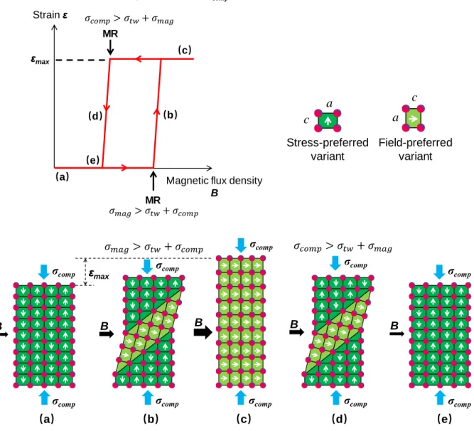
1.1 Overview of ferromagnetic shape memory alloys 11 εmax σcomp σcomp σcomp σcomp B (a) (b) (c) (d) σcomp σcomp σcomp σcomp B B B B σcomp σcomp (e) Magnetic flux density
B Strain ε (b) (c) MR (d) MR (a)
Under a compressive stress σcomp
εmax (e) Field-preferred variant Stress-preferred variant c a a c
Figure 1.5 Schematic of magneto-mechanical loading-induced reversible martensite reorientation.
our attention on the magnetic field-induced martensite reorientation, due to the
twinning stress of Ni2MnGa is very small (< 2 MPa) so that it is easier to be
driven by a weak magnetic field (< 0.8 Tesla) and thus more promising for
engi-neering applications, such as actuators (Asua et al., 2014; Majewska et al., 2010;
12 Introduction
Considering that a reversible strain is generally required in most of the
appli-cations, a rotating magnetic field (Chmielus et al., 2008, 2011; Lawrence et al.,
2016) or a magneto-mechanical biaxial load (Henry et al., 2002; Lai et al., 2008;
Karaca et al., 2006, 2009; Pascan et al., 2015) can be applied on the
mate-rial to drive the reversible martensite reorientation, in which the later method
(magneto-mechanical biaxial load) is more extensively adopted due to its easier
implementation. To obtain the reversible strain by the magneto-mechanical
bi-axial load, normally a cyclic magnetic field and a constant compressive stress
are applied at the same time along perpendicular directions as shown in Fig.
1.5(a). When the horizontal magnetic field is small (e.g., near 0), the material is
in the state of the stress-preferred variant with the short axis along the vertical
compressive stress σcomp(see Fig. 1.5(a)). When the magnetic field is increased
to a value with the effective magnetic stress σmaglarger than the sum of twinning
stress σtw and the mechanical compressive stress σcomp (i.e., satisfying
crite-rion σmag > σtw+ σcomp) (Heczko and Straka, 2004; Straka et al., 2006), the
field-induced martensite reorientation takes place (the stress-preferred variant
transforms to the magnetic field-induced variant) as shown in Fig. 1.5(b). With
the magnetic field further increases, the martensite reorientation will be completed
(with all the material transforming to the state of the field-preferred variant) and
the largest strain εmax of the material is obtained, see Fig. 1.5(c). Then, when the
magnetic field is decreased to a value satisfying criterion σcomp > σtw+ σmag
(Heczko and Straka, 2004; Pascan, 2015; Straka et al., 2006), the reverse
marten-site reorientation from the field-preferred variant to the stress-preferred variant
is activated (see Fig. 1.5(d)). Finally all the materials transform back to the
1.2 Motivations and objectives 13
(see Fig. 1.5(e)). In this process (from (a) to (e) in Fig. 1.5), the competition
between the mechanical and magnetic stresses governs the material state, and the
reversible strain can be achieved in the magnetic actuation cycle. This mechanism
gives the FSMA material the ability to obtain the high frequency deformation
under the high frequency actuation of magneto-mechanical load.
1.2
Motivations and objectives
Compared to other kinds of smart materials, FSMAs have the most attractive advantages:
the large output strain and the high actuation frequency can be obtained at the same
time. Although the material properties and the quasi-static behaviors of FSMAs have
been investigated comprehensively, the existing studies are not enough to have a
pro-found understanding on the high frequency performance of FSMA and to support their
high-frequency applications. The main difficulty in studying the high-frequency
perfor-mance is the complicated coupling of the dynamic effect and thermal effect. The early
experimental studies on the dynamic behaviors of FSMAs revealed loading-frequency
effects and the associated resonance phenomena in the cyclic magnetic field-induced
strain (via cyclic martensite reorientation). That means, the cyclic strain depends on
the actuation frequency, system mass and stiffness and compressive stress level (Henry
et al., 2002; Lai et al., 2008; Karaca et al., 2006; Techapiesancharoenkij et al., 2009). In
addition, the frequency effects were modeled by a spring-mass-damper oscillator model
(Henry, 2002; Sarawate and Dapino, 2008; Tan and Elahinia, 2008) and a discrete twin
boundary dynamic model (Faran et al., 2017; Faran and Shilo, 2016). However, most
of these early experiments were performed for short actuation times (several seconds)
14 Introduction
Techapiesancharoenkij et al., 2009). Besides the studies of the short time actuations,
long-time performance and stability caused research interest recently (Pascan et al.,
2015; Pascan, 2015). It was shown that, during the long time cyclic actuation, the fast
frictional twin boundary motion can induce a quick dissipation heat accumulation and
increase the specimen temperature (“self-heating”) significantly (Pascan et al., 2015),
which is generally ignored in the early studies of the quasi-static and short-time
actu-ations. The temperature variation can influence the performances of FSMAs because
several physical properties related to martensite reorientation of FSMAs are sensitive to
the temperature (Aaltio et al., 2008; Adachi et al., 2017; Glavatska et al., 2002; Heczko
et al., 2017, 2002; Okamoto et al., 2008; Soroka et al., 2018; Sozinov et al., 2017; Straka
et al., 2011a, 2006, 2015, 2012; Vronka et al., 2017; Zreihan et al., 2015). Moreover,
the self-heating can block the magnetic field-induced strain (Pascan et al., 2015; Jugo
et al., 2018). That means, the previously reported large output strain amplitude in the
quasi-static or the short-time actuation on FSMA in fact can not be guaranteed in a
long-time actuation and the self-heating might induce to an instability of magnetic
field-induced strain. However, up to now, the long-time performance of FSMAs still
lack systematic investigation and understanding, particularly the coupling thermal effect
(the influence of the temperature variation) and the dynamic effect during the long-time
high-frequency magnetic actuation.
In this work, we focus on the magneto-thermo-mechanical factors influencing
the long-time high-frequency performance of FSMA. Systematic experiments of the
long-time actuation (> 100 seconds) are performed under different magnetic field
frequency, initial compressive stress and ambient heat-exchange efficiency. Based on
the experimental results and a 1D heat transfer model, the critical conditions to obtain
1.2 Motivations and objectives 15
proposed. Moreover, in-situ Digital Image Correlation (DIC) method is used during the
high-frequency actuation to help us understand the nominal high-frequency responses
from the microscopic view of the temperature-induced phase transformation and the
field-induced martensite reorientation, and their compatibility between different material
variants/phases.
The remaining part of this thesis is organized as follows: Chapter 2 introduces
the experimental setup for the high-frequency magnetic actuation. In Chapter 3, the
systematic long-time actuation tests are reported, particularly the thermal effects on the
long-time stable output strain of FSMA are experimentally revealed and theoretically
understood based on a 1D heat-transfer model. Based on analyses of local strain
evolution and microstructure compatibility, Chapter 4 presents a new mechanism that
magnetic field-driven twin boundary motion and temperature-driven phase boundary
motion can be simultaneously activated during the high-frequency actuation of FSMA.
Chapter 2
Experimental setup
To drive the high-frequency martensite reorientation of FSMA, an experiment system
for the magneto-thermo-mechanical loading and the local strain characterization is
developed. This chapter introduces the details of the experimental setup, including
systems of electromagnetic actuation, ambient controlling, data acquisition and optical
recording.
2.1
Electromagnetic actuation and data acquisition
sys-tem
The high-frequency actuation system used in this work is shown in Fig. 2.1. The whole
system is fixed on a damping grounded frame to prevent system vibrations induced by
the high-frequency actuation. The electromagnet system used in our work is developed
by Bouhnik enterprise. Two cylindrical electromagnet poles (from SIGMAPHI) with
18 Experimental setup
(thus having 25 mm × 25 mm × 5 mm space to install the specimen). To achieve a
high frequency and strong magnetic field, an ac-electric current (up to 130 A and 500
Hz) are applied on the electromagnet coils, which is controlled by using LabVIEW
with help of a NI USB 6251 device. As the high frequency strong ac-electric current
will induce to a quite large heat generation in the coils, a water-cooling system (with
a water flow of constant 15◦C) surrounds the coils to avoid the temperature rise in the coils so that a stable magnetic field can be achieved for the long-time actuation.
The electromagnet is not completely enclosed as we need some in-situ observations on
the specimen surface during the test (see the photo of the experimental setup in Fig.
2.1(c)). With this electromagnet system, a stable cyclic magnetic field with up to ±0.78
Tesla magnetic flux density and 500 Hz frequency can be achieved for a long working
time. The specimen is fixed between the magnetic poles by two Plexiglas holders
with specimen long side along the vertical direction (y-direction). (The Plexiglas is a
non-magnetic material with a low-density and a low thermal conductivity.) A spring
(with stiffness of 5.5 kN/m) is installed on the upper Plexiglas holder which can be
compressed by a micrometer screw and allows us to apply a compressive force along
y-direction. By using this system, the cyclic magnetic field and compressive stress
can be perpendicularly applied on the FSMA specimen. The competition between the
horizontal magnetic field and the vertical compressive stress can drive cyclic martensite
reorientation and achieve high-frequency output strain in the FSMA specimen.
To obtain the specimen responses during the actuation, the specimen strain, stress
and temperature are monitored by different sensors. The changing deformation of the
specimen along y-direction is measured by a laser displacement sensor (LK-H027 from
Keyence) on the upper holder. The force along y-direction is measured by a force
2.1 Electromagnetic actuation and data acquisition system 19 Width 3 mm Field-preferred variant M2 Stress-preferred variant M1
σ
Laser displacement sensor Compressive spring Specimen holder Electromagnet Thermocouple Specimen holder Force sensor M icrometer screw for compression control x y z Thick ness 2 mm Ni-M n-Ga specimenB (b) (a) 2 mm Length 15 mm a c a a c a 0.78T time
σ
x y Optical observation for DIC strain mapsAirflow B Specimen Electromagnet pole Laser displacement
sensor Compressive spring
Micrometer screw for compression control Electromagnet coil Cooling system Specimen holder Damping frame Damping frame Electromagnet coil Electromagnet pole Thermocouple (c)
Figure 2.1 (a) Schematic of actuation system to achieve high-frequency cyclic marten-site reorientation, where the fixed parts (immobile components) during the dynamic actuation are in black, the moving parts (the spring and the upper sample holder) are in blue and the measuring sensors are in red. (b) Schematic of the martensite reorientation between the stress-preferred martensite variant (M1) and the magnetic-field-preferred martensite variant (M2) in Ni-Mn-Ga specimen under the magneto-mechanical actua-tion. Approximated tetragonal martensite variant of one short axis (c-axis) and two long axes (a-axis) are adopted and the difference between a and c is shown exaggeratedly here. (c) Photo of the experimental setup for high-frequency magnetic actuation.
20 Experimental setup
to have a precise description on the specimen responses, we acquire 25 data points
of deformation and force per strain cycle. The global temperature of the specimen is
monitored by a thermocouple (K-type, 0.5 mm sheath diameter) at the lower end of the
specimen with the sampling rate of 170 Hz. All the above mentioned data acquisitions
are performed on the same computer to guarantee a high time accuracy (10−7second) of data synchronization. In summary, for a test with an input of cyclic magnetic field,
the evolutions of strain, stress and temperature of the specimen can be acquired as the
typical results shown in Fig. 2.2. It’s seen that the acquired data points are enough to
provide a good description of the specimen responses respectively.
7.99 7.995 8 8.005 8.01 −1 0 1 Magnetic field B (T) f = 90Hz, σ ini = 0.4 MPa 7.99 7.995 8 8.005 8.01 −2 0 2 4 6 Strain ε (%) 7.99 7.995 8 8.005 8.01 0 2 4 6 Stress σ (MPa) 7.99 7.995 8 8.005 8.01 20 30 40 50 Time (s) Temperature T ( ° C)
2.2 Ambient controlling during the test 21
2.2
Ambient controlling during the test
To investigate the ambient effect, an airflow with a constant temperature (around the
room temperature) are forced to pass through the specimen to change the heat-exchange
efficiency between the specimen and the ambient during the magnetic actuation. The
airflow velocity can be controlled by a valve and measured by a portable airflow
velocity indicator. The heat–exchange efficiency can be evaluated by a characteristic
heat-relaxation time th (He et al., 2010; He and Sun, 2010), which is measured as
follows:
The specimen is held between two electromagnet poles during the tests and heated
Time (s) Sa m p le te m p e ra tu re ( oC )
Experimental data of temperature relaxation Heat-convection relaxation equation
Figure 2.3 Temperature relaxation of Ni-Mn-Ga single crystal sample (2 × 3 × 15 mm) under the ambient airflow of 15 m/s. The fitted characteristic heat-relaxation time this
22 Experimental setup
due to the high-frequency frictional twin boundary motion. To determine the
character-istic heat−relaxation time th, the evolution of the specimen temperature after turning
off the magnetic field is measured in a constant ambient airflow. Because there is no
heat generation in the specimen, the temperature relaxation is only due to the heat
convection from the specimen to the ambient. The value of the heat-relaxation time th
is determined by fitting the experimental cooling curve with an exponential equation
T = Tr oom + (T0− Tr oom) · e −t
th, which describes the heat-convection relaxation (He
et al., 2010; He and Sun, 2010). For example, in Fig. 2.3, the value of that the ambient
airflow velocity of 15 m/s is determined to be 8.8 s. By using this method, that different
ambient conditions can be experimentally measured.
2.3
Optical observation on the specimen surface
During the tests, a CMOS camera of 2048×1088 pixels (Basler ac A2000-340 km)
with Nikkor lens is used to record the optical images of the specimen surface, so
that after the test, the recorded images can be processed by Digital Image Correlation
(DIC) software Vic-2D (Correlated Solutions) to obtain the local strain maps. But
considering the limitation of recording rate (maximum 100 frames/s) of the imaging
system, it is difficult to directly record enough frames (such as 10 frames/cycle) in a
single deformation cycle (with a period of 5.56 ms per cycle at an actuation frequency of
180 Hz). To solve this problem, the recording frequency is set as fimage = n·mn+1· fstr ain,
as shown in Fig. 2.4, where fstr ain is the strain frequency, n represents the number of
the images needed to describe a strain cycle (n ≫1) and m represents the number of
the strain cycles where an image is recorded). This setting can ensure that the strain
2.3 Optical observation on the specimen surface 23 1/fstrain 1/fimage m/fstrain
…
1 / (nfstrain) Time StrainFigure 2.4 Schematic of the optical imaging method during high-frequency deformation.
difference between two adjacently recorded images, see Fig. 2.4. In this way, the
phase difference (n· f1
str ain) is set as1/n of the strain cycle, which means n continuously
recorded images with different phases can describe a complete strain cycle. It’s noted
that although the continuous recorded images are from different strain cycle, they are
equivalent to the images from the single strain cycle because the material behaviors are
repeated for different cycles at the stable state. By using this recording system and the
method, the local strain field evolution during the high-frequency magnetic actuation
can be obtained by using the method of Digital Image Correlation (Vic-2D), which
helps us understand the mechanism of the macroscopic performance of FSMA from a
Chapter 3
Thermal effects on high-frequency
magnetic field-induced martensite
reorientation
Ferromagnetic Shape Memory Alloys (FSMAs) exhibit large strains by the
magnetic-field-induced martensite reorientation. But, due to the high-frequency magnetic-field-induced
cyclic frictional martensite twin boundary motion in FSMAs, the dissipation heat can
cause a large temperature rise. Thus, the output strain amplitude of FSMAs would
decrease significantly if the temperature increases to be high enough to trigger the
Martensite-Austenite phase transformation. Such thermal effects on the dynamic
re-sponses of FSMAs are unclear in literature because most existing dynamic experiments
were performed only for a short-time period (a few seconds) to avoid the temperature
rise. In this chapter, systematic long-time experiments (> 100 seconds) on a
26 Thermal effects on high-frequency magnetic field-induced martensite reorientation
compressive stress and ambient airflow velocity. It is found that, during the long-time
actuation, the specimen temperature increases and then saturates at a certain level (stable
temperature) while the strain oscillation evolves to a stable cycle; both the stable
tem-perature and the stable strain amplitude depend on the frequency, the stress level and the
heat exchange condition (i.e., ambient airflow velocity). Particularly, when the specimen
temperature reaches a critical level to partially transform the martensite to the austenite,
the output strain amplitude reduces suddenly because of less martensite reorientation.
Changing the ambient heat-exchange condition (by the airflow) can modify the
speci-men temperature evolution to avoid the phase transformation, but it also changes the
behaviors of the martensite reorientation that is sensitive to temperature. Eventually, the
output strain amplitude depends on the airflow velocity non-monotonically, i.e., there
exists a critical heat exchange condition to achieve the maximum stable strain amplitude.
Based on the systematic experiments and a simplified one-dimensional heat-transfer
model, the critical condition can be determined. The new experimental phenomena of
the thermal effects can be well understood and described by the heat-transfer model.
Further, instead of avoiding the temperature rise and the phase transformation, we
propose to take advantage of the interaction between the temperature-induced phase
transformation and the magnetic-field-induced martensite reorientation to develop a
special “isothermal” FSMA actuator with a tunable output strain amplitude and a
con-stant working temperature. This chapter provides systematic experimental data and
theoretical analysis for understanding the thermo-magneto-mechanical coupling in
3.1 Introduction 27
3.1
Introduction
Ferromagnetic Shape Memory Alloy is a typical smart material with
thermo-magneto-mechanical coupling, which can provide a large recoverable deformation (up to 10%
strain) by the temperature-, stress- or magnetic-field-induced phase transformation
(PT) (Arndt et al., 2006; Bruno et al., 2017; Cisse et al., 2016; Haldar et al., 2014;
Kainuma et al., 2006; Karaca et al., 2006; Liu et al., 2014; Rogovoy and Stolbova,
2016; Sehitoglu et al., 2012; Sutou et al., 2004) and the magneto-mechanically-driven
martensite reorientation (MR) (Chen et al., 2013a, 2014; Cisse et al., 2016; Dai et al.,
2018; He et al., 2011, 2012; Heczko et al., 2016; Karaca et al., 2006; Kiefer and
Lagoudas, 2005, 2004; Molnar et al., 2008; Murray et al., 2000; O’Handley et al.,
2000), leading to various potential engineering applications. Normally, the martensitic
phase transformation of FSMA needs to be triggered by a high-level stress or a strong
magnetic field, and is accompanied by large latent heat release/absorption that can be
used as energy harvesters (Basaran, 2009; Saren et al., 2015; Sayyaadi and Farsangi,
2015) and magneto-caloric refrigerators (Franco and Conde, 2012; Qu et al., 2017;
Zhao et al., 2017). On the other hand, the martensite reorientation can be driven by a
low stress (∼ 1 MPa) or a weak magnetic field (< 1 Tesla) and has small hysteresis and
energy dissipation, which are suitable for the applications such as actuators (Asua et al.,
2014; Majewska et al., 2010; Smith et al., 2014; Techapiesancharoenkij et al., 2009; Yin
et al., 2016) and sensors (Hobza et al., 2018; Sarawate and Dapino, 2006; Stephan et al.,
2011; Yin et al., 2016). Particularly, there exists a special twin boundary (so-called
Type II twin boundary) with ultra-low frictional twinning stress (∼ 0.2 MPa) during the
field- and/or stress-driven martensite reorientation in FSMA Ni-Mn-Ga single crystal,
28 Thermal effects on high-frequency magnetic field-induced martensite reorientation
deviation is small, e.g., the characteristic angle γ = 90.37◦is close to 90◦of a tetragonal lattice) (Chulist et al., 2013; Heczko et al., 2013; Liu and Xie, 2003; Pascan et al., 2015;
Sozinov et al., 2011; Straka et al., 2012, 2011b; Zou et al., 2018; Zreihan et al., 2015).
Such low driving force and small dissipation make FSMA a promising candidate for
actuators.
Although the temperature rise due to the low energy dissipation of martensite
reorientation in FSMA is negligible in the slow or quasi-static loading conditions,
it cannot be ignored in high-frequency magnetic loadings (> 100 Hz) because the
dissipation due to the frictional twin boundary motion of martensite reorientation
(Blanter et al., 2007; Cui et al., 2017; He et al., 2012, 2011; Heczko et al., 2016; Karaca
et al., 2006; Kiefer and Lagoudas, 2005, 2004; Molnar et al., 2008; Murray et al.,
2000; O’Handley et al., 2000; Pagounis et al., 2014; Yu et al., 2015) and the eddy
current inside the material can accumulate quickly to induce significant temperature
rise (Henry et al., 2002; Henry, 2002; Lai, 2009; Lai et al., 2008). Moreover, several
physical properties related to martensite reorientation of FSMA are sensitive to the
temperature (Aaltio et al., 2008; Adachi et al., 2017; Glavatska et al., 2002; Heczko
et al., 2017, 2002; Okamoto et al., 2008; Soroka et al., 2018; Sozinov et al., 2017;
Straka et al., 2011a, 2006, 2015, 2012; Vronka et al., 2017; Zreihan et al., 2015). That
is why most existing high-frequency dynamic experiments on FSMA were performed
only for a short-time period to avoid significant temperature rise (Henry et al., 2002;
Henry, 2002; Lai, 2009; Lai et al., 2008). In such short-time experiments, although the
output strain seems to be stable with nearly constant strain amplitude, the temperature
of the specimen keeps increasing without reaching the steady state, e.g., the temperature
increasing rate during the short-time actuation of 20 seconds is larger than 0.5◦C/s in (Pascan, 2015) and 0.3◦C/s in (Lai, 2009). Therefore, such short-time actuation
3.1 Introduction 29
systems are not strictly stable since not all the thermo-magneto-mechanical responses
have reached the steady states. Thus, it’s still unknown whether the large output strain
of FSMA under high-frequency magnetic loadings reported in the literature can be
guaranteed for the long-time performance (e.g., > 100 s) or not.
One of the main problems caused by the temperature rise is the temperature-induced
Martensite-to-Austenite (M-to-A) phase transformation (Auricchio et al., 2014;
Bhat-tacharya, 2003; Iadicola and Shaw, 2004; Otsuka and Wayman, 1999), which will
disturb the field-induced martensite reorientation in the long-time actuation of FSMA.
To my best knowledge, studies about the effect of phase transformation on the
marten-site reorientation of FSMA are seldom reported in the literature. This is possibly due
to the fact that the stress and magnetic field levels for martensite reorientation are too
small to trigger the phase transformation (Haldar et al., 2014; Karaca et al., 2006, 2009),
and that the energy dissipation of martensite reorientation per cycle is small (Chen
et al., 2013a; Karaca et al., 2006). However, in the high-frequency magnetic loadings
(e.g., beyond 100 Hz, such high-frequency working condition is a main advantage of
FSMA actuators over the traditional shape memory alloy (SMA) actuators), the small
dissipation heat can accumulate and thus generate significant temperature rise (Lai,
2009; Pascan, 2015; Pascan et al., 2015) especially when the ambient heat exchange
is weak (e.g., in still air). The effects of ambient heat exchange on the phase
trans-formation and the mechanical detrans-formation of traditional SMAs have been reported
in the literature such as (Blanter et al., 2007; Brinson et al., 2004; He and Sun, 2010,
2011; He et al., 2010; Shaw and Kyriakides, 1995). It is predicted that controlling the
ambient heat exchange condition can be a solution to the problem of the temperature
rise in FSMA under high-frequency magnetic loadings. Therefore, in my study on the
30 Thermal effects on high-frequency magnetic field-induced martensite reorientation
velocities is forced to pass through the FSMA specimen so that the specimen can be in
different heat exchange conditions. Different stable states were finally reached in the
specimen, and we found a non-monotonic dependence of the output strain amplitude on
the airflow velocity. Based on such dependence and a heat balance analysis, the thermal
effects on the dynamic behaviors of FSMA are revealed for the first time. Further, the
critical thermo-magneto-mechanical conditions to achieve a large stable output strain
are provided.
It is normally expected that, when the ambient airflow (heat exchange efficiency)
is sufficiently strong (of large velocity), the specimen temperature can be kept lower
than the phase transformation temperature (such as the Austenite starting temperature
As or the martensite finishing temperature Mf) so as to avoid the phase transformation
and maintain the large strain amplitude of the field-induced martensite reorientation.
However, it is founded in my study that while the phase transformation can be avoided,
the output strain amplitude of FSMA was reduced significantly when the steady-state
temperature was much lower than As or Mf. This is attributed to the fact that the
internal friction of martensite reorientation is sensitive to temperature: the frictional
twinning stress for the Type I twin boundary increases with decreasing temperature
(Heczko and Straka, 2003; Soroka et al., 2018; Sozinov et al., 2017; Straka et al., 2012,
2011a, 2006). Therefore, for the optimal condition of the largest stable cyclic strain
in dynamic actuation, the temperature of FSMA should be kept close to (but lower
than) the characteristic phase transformation temperature by applying a proper ambient
airflow.
On the other hand, if the applied airflow is weak (of low velocity), the FSMA