HAL Id: pastel-00848627
https://pastel.archives-ouvertes.fr/pastel-00848627
Submitted on 26 Jul 2013HAL is a multi-disciplinary open access
archive for the deposit and dissemination of sci-entific research documents, whether they are pub-lished or not. The documents may come from teaching and research institutions in France or
L’archive ouverte pluridisciplinaire HAL, est destinée au dépôt et à la diffusion de documents scientifiques de niveau recherche, publiés ou non, émanant des établissements d’enseignement et de recherche français ou étrangers, des laboratoires
Study of Ultra Wide Band Modulated Backscattering
Based RFID Systems
Francesco Guidi
To cite this version:
Francesco Guidi. Study of Ultra Wide Band Modulated Backscattering Based RFID Systems. Elec-tromagnetism. EDX, 2013. English. �pastel-00848627�
In fulfillment of the requirements for the joint Ph.D. degrees of
ECOLE POLYTECHNIQUE PARISTECH
Ecole Doctorale de l’X - Sp´ecialit´e Informatique and
UNIVERSIT `
A DEGLI STUDI DI BOLOGNA
Dipartimento di Ingegneria dell’Energia Elettrica e dell’Informazione “Guglielmo Marconi”
STUDY OF ULTRA WIDE BAND
MODULATED BACKSCATTERING
BASED RFID SYSTEMS
Ph.D. Candidate
FRANCESCO GUIDI
Jury Members
Gha¨ıs El Zein
Klaus Witrisal
Martine Li´
enard
Davide Dardari
Alain Sibille
Marco Chiani
Raffaele D’Errico
Reviewer
Reviewer
Examiner
(Co-Supervisor) Examiner
Supervisor
Supervisor
Invited Member
15 May 2013
INDEX TERMS
UWB
RFID
Backscatter
Tag
Detection
Acknowledgment
I would like to express my deepest gratitude to all those who provided me the possibility to complete this report, which includes three years and a half of efforts, work and cooperation with many brilliant researchers.
Among all, a special thank goes to my advisors, Prof. Alain Sibille, Prof. Davide Dardari and Prof. Marco Chiani, whose contribution in stimulat-ing suggestions and encouragement, helped me to coordinate my activity. Their valuable competences, knowledge and willingness have transmitted me passion for research. I would like also to thank Prof. Christophe Roblin, who acted like an advisor during these years, and his suggestions and expe-rience were very precious to overcome many difficulties encountered during the work. I will never forget his help. I would like to express my gratitude to the reviewers, Prof. Klaus Witrisal and Prof. Gha¨ıs El Zein, for their very fruitful comments and for having accepted to review my manuscript, and to Prof. Martine Li´enard, for taking part to the jury and her comments on my work. A particular thank goes to Raffaele D’Errico for his help and suggestions at the beginning of my thesis, and for his presence in the jury at my defense.
I would like to thank the RFM group at Telecom ParisTech and all the group at ENSTA-UEI for having hosted part of my activity. When I arrived the first time in Paris, the help of Amir Yousuf was fundamental for my integration with the staff members. I will be always grateful for his patience with me. I would like also to express my gratitude to Gilles Poncelet for his technical support for the measurements equipment, and to Moussa, Yunfei, Zeinab, Taghrid, Luca, Reda, Lila, Fabrice, Francesco and David, who shared with me great moments.
For what my Italian activity was concerned, a particular thank goes to the Telecommunication group at University of Bologna, Cesena Campus, which hosted me. I would like to mention Nico for all the efforts and the moments shared in the European project SELECT, or for the great ”work experience” in USA. Unforgettable. In Cesena, I found also a great friends as Simone, with whom I shared many coffee breaks and a real friendship. I would like
also to thank the other group members Andrea, Enrico, Matteo, Stefano, Vincenzo, Anna and Bita. Last, but not least, Mario. During the pursuing of our PhDs and studies, we shared a friendship that has become stronger and stronger during years!
Un ringraziamento particolare va alla mia famiglia, ai miei genitori che mi hanno sempre sostenuto in ogni scelta e in ogni momento, e a mio fratello e a mia sorella che sono sempre stati presenti. Senza di loro la mia vita sarebbe
molto pi`u monotona. Ringrazio anche Luca B. e Caterina, che mi ha reso
orgoglioso di essere zio.
Vorrei ringraziare Nico T. per la sua amicizia che dura ormai da quando abbiamo 8 anni, Andre, che `e sempre stato presente nonostante la lontananza e si `e sempre dimostrato un vero amico, e Segale e Jack, con cui ho condiviso delle vacanze indimenticabili. Nonostante gli anni trascorsi la nostra amicizia non `e mai mutata! Ricordo anche il supporto di Fiorella, Paola, Giulia, Luca C., Viola, Flavia, Fede R., Fede G., Tore, Marco, Cristina e Fra. che han condiviso con me diversi momenti a Cesena. Ringrazio anche i ragazzi dello Stock 84 per i calcetti e per il supporto, e Filo, che `e tornato a Parigi per sentire la mia discussione.
Un ringraziamento speciale a Anna, Luna, Mary, Vania e Yole, che mi son sempre state vicine in ogni difficolt`a, e mi hanno cucinato piatti eccezionali nel corso del mio soggiorno a Parigi (a base di pasta). Ringrazio Macu e Fede per le nostre cene parigine-vegetariane, e Carla, Valentina e Alessia per le serate trascorse insieme ogni tanto lungo la Senna. Last, but not least, Denis (”il migliore amico di Parigi”). La prima persona che ho conosciuto per sbaglio in Francia, `e diventata nel tempo un vero amico e un supporto nelle difficolt`a. Senza contare l’aiuto per il ”pot” e la pizza speciale preparata!
I would like to thank all the people I have met during my great stay at MEASE, where I had the possibility to discover the world of CIUP. I will never forget this period of my life.
Un ringraziamento finale a Anna per il supporto via skype durante il mio soggiorno parigino, e soprattutto la pazienza che ha avuto nei momenti finali di stress...”Ma `e che se guardo gi`u c’ho le vertigini”
Abstract (English)
In the recent years, the idea of the Internet of Things, that is to say a perva-sive presence of electronics devices embedded in every-day objects, is facing a rapid adoption and will create a new era in the Internet scenario. Among all the technologies, radio frequency identification (RFID) seems one of the most promising. In addition, when tag cost, size and power consumption become stringent requirements, passive or semi-passive solutions based on the modulation of the backscatter signal represent a good choice. Thus, this work was developed with the intent to study UWB RFID systems based on the modulation of the backscattered signal considering different related issues. The European Project SELECT gave the motivation and the op-portunity to investigate the combination of UWB and RFID technologies, which are expected together to overcome many limitations of current nar-rowband RFID devices. The consciousness that, before the design of proper system architectures for backscatter communication, it was fundamental to understand the basic electromagnetic mechanisms underlying the interaction between readers and tags, was reflected in a wide investigation ranging from EM characterization of backscatter links to the definition and design of sig-nal structures and transmission schemes. This dual need motivated a joint french-italian agreement between two laboratories for the supervision of the thesis. In particular, in the course of the work carried out in France, the analysis of the tag backscattering has been analyzed in several ways, both in ideal and real conditions. The results and competences were then exploited in Italy, in order to study an architecture able to ensure a reliable commu-nication between reader and tag. The thesis and the work are organized as follows.
Chapter 1 is a general overview about current UWB RFID technologies, discussing their main limitation when adopted in industrial environments.
In Chapter 2 the tag backscattering properties are analyzed in several
ways, both in ideal and real conditions. Simple approaches for the tag
antenna backscattering component reconstruction are shown and validated, with the final conclusion that the same results can be obtained by
perform-ing direct simulations/measurements or by means of the superposition and reciprocity principles.
Chapter 3 addresses the interaction between passive UWB RFID antennas with close disturbers, the study being based on measurements in an anechoic chamber. In particular, it is shown how the tag radiation characteristics are greatly affected by the presence of an object and the measured data are further exploited to compute detection and localization coverage maps using the system set-up described in Chapter 4 and the SNR threshold derived in Chapter 5. The interaction between a tag and a close metallic reflector is also investigated.
Chapter 4 concentrates on an UWB RFID system based on the mod-ulation of the backscattered signals, highlighting potential implementation issues. Corresponding solutions are proposed in order to counteract the main difficulties. The joint adoption of code acquisition schemes with codes prop-erly designed to combat all the system non-idealities is subsequently investi-gated in order to guarantee reliable performance.
Chapter 5 shows, in particular, that the joint use of orthogonal Gold codes with proper low-complexity detection and synchronization schemes involving bin-dependent thresholding is a promising solution to overcome implementa-tion impairments, such as tag clock drift and near-far effects.
Chapter 6 describes an UWB RFID reader and tag architecture for data communication based on backscatter modulation, which is able to work in the presence of strong clutter and interference. The achievable range and performance are investigated, showing that clutter is the main limiting factor and that it can be mitigated or suppressed through the architecture proposed and the adoption of zero mean spreading codes.
The manuscript contains a final conclusions and perspectives, where it is stressed that a UWB RFID system based on the modulation of the backscat-ter signal is a promising candidate for the next RFID generation, in backscat-terms of cost-performance trade-off.
R´
esum´
e (Fran¸
cais)
Depuis quelques ann´ees le nouveau paradigme “d’internet des objets”, qui se traduit par la connection des objets de la vie quotidienne `a internet grˆace `
a des dispositifs ´electroniques int´egr´es, est devenu plus qu’un simple con-cept et a commenc´e `a entrer dans la r´ealit´e. Il en est ainsi des syst`emes d’identification par radiofr´equence (RFID), qui font partie des technologies
disponibles. Lorsque le coˆut et la taille des “tags” deviennent des
exi-gences pr´epond´erantes, l’adoption de tags (semi-)passifs fond´es sur la modu-lation d’un signal r´etro diffus´e repr´esente une solution attractive. En outre, l’utilisation de techniques ultra large bande (ULB) apporte des avantages propres `a favoriser le remplacement d’une partie des syst`emes RFID actuels, fonctionnant en UHF et qui souffrent de certains d´efauts tels qu’une trop forte consommation ou une faible robustesse en pr´esence d’interf´erences ou de canaux multi-trajets. La th`ese de doctorat se place dans ce contexte: elle a pour objectif l’´etude des syst`emes ULB RFID semi-passifs et se situe dans le cadre du projet europ´een SELECT, qui vise `a d´evelopper et `a ´evaluer un tel syst`eme. La prise de conscience qu’il ´etait fondamental de comprendre les m´ecanismes ´electromagn´etiques intrins`eques `a la communication lecteur-tag, pr´ealablement `a la conception du syst`eme, s’est traduite par la mise en œuvre d’une collaboration ´etroite franitalienne dans le cadre d’une co-tutelle de th`ese et du projet SELECT. C’est donc au d´epart autour d’une analyse fine et d’une mod´elisation des aspects antennaires et du canal radio entre le lecteur et le tag que la 1re partie du travail s’est construite (par-tie fran¸caise). La 2nde par(par-tie a exploit´e ces travaux pour l’´elaboration des sch´emas de modulation et de codage du lecteur et du tag pour les syst`emes semi-passifs (partie italienne). L’ensemble de ces travaux est d´ecrit dans le manuscrit.
Le chapitre 1 montre un aper¸cu g´en´eral des technologies RFID actuelles et des techniques ULB et en discute les principales limitations dans le cas des environnements industriels.
Le chapitre 2 traite de plusieurs fa¸cons de l’analyse des signaux de r´ etro-diffusion des tags, au d´epart dans une situation id´eale puis dans des cas
plus r´ealistes. Des approches simples pour la reconstruction de signal de r´etrodiffusion sont pr´esent´ees et valid´ees, d’o`u il en ressort que les mˆemes r´esultats peuvent ˆetre obtenus par des simulations/mesures directes ou alter-nativement par l’exploitation des principes de superposition et de r´eciprocit´e. Les m´ethodes propos´ees permettent ainsi d’accrotre la matrise des ph´enom`enes qui apparaissent dans la r´etrodiffusion et de limiter la complexit´e ou la lour-deur des simulations et des mesures.
Le chapitre 3 aborde l’´etude de l’interaction compliqu´ee entre les antennes des tags ULB et divers perturbateurs repr´esentant les objets sur lesquels ils seraient plac´es dans des cas d’usage. L’´etude s’appuie sur des mesures en chambre an´echo¨ıque et on montre en particulier comment les caract´eristiques de rayonnement du tag sont grandement affect´ees par la pr´esence de l’objet. Les donn´ees de mesure sont ensuite exploit´ees pour ´evaluer sous forme de cartes de couverture les performances potentielles du syst`eme RFID en ter-mes de d´etection et de localisation, pour des param`etres repr´esentant la con-figuration d´ecrite dans le chapitre 4 et le rapport signal-bruit obtenu dans le chapitre 5. L’interaction entre un tag et un r´eflecteur m´etallique proche est ´
egalement ´etudi´ee.
Le chapitre 4 est consacr´e `a l’´etude globale du syst`eme ULB RFID. Di-verses probl´ematiques importantes sont expos´ees et des solutions propos´ees. L’adoption conjointe de sch´emas robustes d’acquisition de la phase des codes grˆace `a des codes bien con¸cus pour combattre toutes les non id´ealit´es du syst`eme est ainsi ´etudi´ee, afin de garantir des performances fiables.
Le chapitre 5 se concentre sur l’utilisation de codes de Gold orthogonaux avec une strat´egie de d´etection de tag mettant en jeu un seuillage fonction de la case temporelle, qui apparat ˆetre une solution prometteuse pour combattre les effets d’interf´erence “near-far” et pour traiter les probl´ematiques soulev´ees dans le chapitre pr´ec´edent.
Le chapitre 6 d´eveloppe une architecture lecteur-tag pour la communica-tion reposant sur la d´emodulation des donn´ees contenues dans la m´emoire du tag, capable d’op´erer en fort fouillis d’environnement et en pr´esence d’interf´erences.
Enfin le manuscrit se termine par une conclusion et des perspectives. Les r´esultats obtenus montrent ainsi que les solutions ULB propos´ees ont la ca-pacit´e de r´epondre `a certains besoins de syst`emes RFID, alliant performance et faible coˆut.
Sommario (Italiano)
Recentemente il concetto de “l’internet degli oggetti” `e diventato pi`u che
una semplice idea. L’espressione, coniata dall’AutoID labs (MIT, USA),
viene riferita alla presenza pervasiva di dispositivi elettronici sugli oggetti della vita quotidiana, permettendo di mappare il mondo reale in quello di Internet. Fra le tecnologie a disposizione, i sistemi d’identificazione a radio-frequenza (RFID) rappresentano una delle soluzioni pi`u appetibili.
Quando il costo e le dimensioni dei tag RFID diventano requisiti im-portanti da soddisfare, l’adozione di tag (semi-)passivi rappresenta la scelta migliore, non essendo dotati di una batteria che alimenti il trasmettitore. Una delle tecniche pi`u diffuse per la comunicazione tra reader e tag semi-passivi consiste nella modulazione del segnale riflesso tramite opportune variazioni del carico connesso all’antenna del tag. Inoltre l’utilizzo congiunto delle tec-nologie a banda ultralarga (UWB) e RFID, costituisce un valido candidato per sostituire gli attuali sistemi RFID che operano nelle bande UHF e sono affetti da limitazioni ben note quali un pi`u elevato consumo di potenza o una scarsa robustezza alla presenza di forte interferenza o di canali multi-percorso. Per queste ragioni, nate dall’urgenza di trovare una nuova tecnologia che possa sostituire quella attuale, la tesi di dottorato ha come scopo primario lo studio dei sistemi UWB RFID semi-passivi attraverso una collaborazione universitaria italo-francese. Da un lato, sfruttando le competenze del labo-ratorio francese, si sono caratterizzati i fenomeni che sono alla base del mec-canismo di riflessione, sia per antenne isolate che in presenza di perturbatori in prossimit`a del tag. Le competenze acquisite sono state poi integrate con il background italiano per studiare un’architettura reader-tag che permetta di discriminare la presenza di utenti nello scenario anche in mezzo a una forte interferenza, riflessioni dell’ambiente circostante, e tutte le non-idealit`a che emergono quando un sistema reale deve essere implementato.
La collaborazione si `e inserita nell’ambito del progetto europeo SELECT, che fra i vari obiettivi si pone quello della realizzazione di un sistema UWB RFID semi-passivo. La tesi `e stata organizzata come segue.
con particolare enfasi sul contesto e sulle motivazioni alla base di questo lavoro.
Il capitolo 2 `e dedicato allo studio del meccanismo di riflessione dell’antenna tag, utilizzando i principi di reciprocit`a e di sovrapposizione degli effetti. Si propone anche una metodologia alternativa per legare il segnale riflesso alla funzione di trasferimento del tag.
L’interazione tra il tag e oggetti posti nelle vicinanze viene analizzato nel capitolo 3. Attraverso una campagna di misure, si `e valutato come le carat-teristiche elettromagnetiche delle antenne variano in presenza di un pertur-batore. Le misure sono state poi rielaborate (sfruttando le relazioni del capi-tolo 2) per valutare le prestazioni di detection e di localizzazione del sistema UWB RFID sotto forma di mappe di copertura in uno scenario controllato. Nell’ultima parte del capitolo si analizza l’interazione tag-oggetto metallico, e si mostrano gli effetti sulle caratteristiche elettromagnetiche dell’antenna.
Nel capitolo 4 si propone un’architettura reader-tag dove vengono de-scritti alcuni dei problemi che emergono durante la realizzazione del sistema proposto. Differenti famiglie di codici sono inoltre studiate per valutare quale garantisce le prestazioni migliori negli scenari considerati.
Il capitolo 5 mostra che l’utilizzo congiunto di codici di Gold ortogonali e di schemi di acquisizione della fase dei codici garantisce buone prestazioni anche in presenza di forte interferenza e di non-idealit`a. Viene inoltre pro-posto uno schema che permetta di rilevare correttamente la presenza di un tag limitando gli effetti di interferenza near-far dovuti alla natura passiva della comunicazione.
Una volta che il tag `e stato rilevato, si deve valutare la qualit`a della comunicazione RFID. A tale scopo, nel capitolo 6 si propone un’architettura reader-tag in cui il payload contenuto nella memoria del tag viene modulato in modo opportuno mitigando gli effetti del clutter e dell’interferenza.
La tesi si chiude con le conclusioni e le prospettive future. I risultati ottenuti hanno mostrato che il sistema UWB RFID proposto rappresenta un serio candidato per la nuova generazione di sistemi RFID, garantendo un buon trade-off in termini di prestazioni e costo.
Contents
List of Figures xxiii
List of Tables xxv
List of Acronyms xxx
Introduction xxxi
Author Contributions xxxv
List of publications xxxvii
1 State of the art of RFID and UWB Technologies 1
1.1 Introduction . . . 1
1.2 The RFID Concept . . . 1
1.3 Main Characteristics of RFID Systems and Technologies . . . 3
1.3.1 Active Tags . . . 5
1.3.2 Passive and Semi-Passive Tags . . . 5
1.3.3 SAW Tags . . . 8
1.4 Summary of the Main radio-frequency identification (RFID) Tag Characteristics . . . 9
1.5 Basic Features of UWB Technologies . . . 10
1.5.1 UWB History . . . 10
1.5.2 Characteristics of UWB Signals . . . 11
1.5.3 Impulse Radio UWB . . . 14
1.6 Passive and Semi-Passive UWB-RFID . . . 15
1.6.1 UWB Antenna Backscattering . . . 16
1.7 UWB RFID Backscattering: The State of The Art . . . 17
2 Electromagnetic Analysis of UWB RFID Tag Backscattering 23
2.1 Introduction . . . 23
2.2 Application of Superposition and Reciprocity Principles in Ideal Scenarios . . . 23
2.3 Proposed Procedures for Tag Backscattering Reconstruction . 26 2.4 Application of Superposition and Reciprocity Principles in Presence of Scatterers . . . 33
2.5 Proposed Methodologies in Presence of Scatterers . . . 37
2.5.1 General Representation . . . 37
2.6 A Different Approach for Tag Backscattering Characterization 43 2.7 Conclusions . . . 46
3 Tag Backscattering Characterization in Presence of Nearby Objects 47 3.1 Introduction . . . 47
3.2 Tag Interaction with Objects . . . 48
3.2.1 Measurement Set-Up . . . 48
3.2.2 Results . . . 51
3.3 Impact of Tag Backscattering Characteristics on the Detection Coverage . . . 58
3.3.1 Case Study Scenario . . . 58
3.3.2 Simulation Results . . . 59
3.4 A Case Study: Tag Interaction with a Perfect Electric Conductor 61 3.4.1 Antenna Backscattering Measurements in Presence of Metal . . . 62
3.4.2 Simulation of the Antenna Backscattering . . . 64
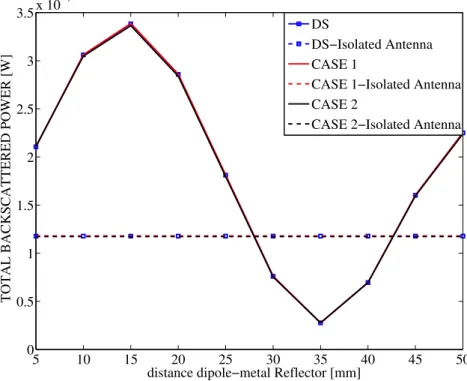
3.5 Total Backscattered Energy in Presence of Metal . . . 70
3.6 Conclusions . . . 71
4 UWB RFID System Architecture and Implementation Is-sues 75 4.1 Introduction . . . 75
4.2 System Design . . . 76
4.3 Reader Transmitted Signal Format . . . 77
4.4 Tag Backscatter Modulation . . . 78
4.5 Design Issues . . . 80
4.5.1 Synchronization Procedure . . . 81
4.5.2 ADC design analysis . . . 82
4.5.3 Tag Clock Drift Model . . . 87
4.6 Tag-to-Reader Communication . . . 87
4.8 Tags Code Assignment Strategies . . . 91
4.9 Inter-Reader Interference . . . 96
4.10 Conclusions . . . 99
5 Robust Tag Detection Scheme to the Presence of Interference and Drift 101 5.1 Introduction . . . 101
5.2 Signal De-Spreading . . . 102
5.3 Tag Detection . . . 103
5.3.1 Threshold Evaluation Criteria . . . 105
5.4 Numerical Results . . . 111
5.4.1 Simulation Parameters . . . 111
5.4.2 System Design . . . 112
5.4.3 Results . . . 114
5.4.4 Considerations on Threshold SNR for Detection Cov-erage in Sec. 3.3 . . . 117
5.5 Conclusions . . . 118
6 Processing Scheme for Data Demodulation 121 6.1 Introduction . . . 121
6.2 System Model . . . 121
6.3 Laboratory Measurements . . . 127
6.4 Numerical Results . . . 131
6.4.1 System Performance in a Single-Tag Scenario . . . 131
6.5 System performance in a Multi-Tags Scenario . . . 134
6.5.1 BER–SIR in Multi-Tags Anechoic Chamber Scenario with Artificial Clutter . . . 134
6.5.2 BER-Ns in Multi-Tag Laboratory Scenario . . . 135
6.5.3 BER-Ns in Multi-Tags Multipath Scenario with Arti-ficial Clutter . . . 136
6.6 Conclusions . . . 137
A Theoretical Analysis on the SQNR Before and After De-spreading 143 A.1 Analysis at Low SNR . . . 145
A.2 Analysis at High SNR . . . 145
B General Solutions for Readers Medium Access Control 149 B.1 Codewords Assignment . . . 149
B.1.1 Same Codewords Assigned to all the Readers . . . 149
List of Figures
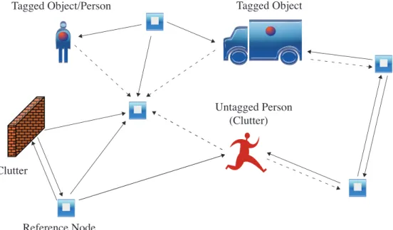
1.1 Example of a scenario with some reference nodes and tagged
and untagged objects. . . 3
1.2 Classic RFID scenario with a reader interrogating several tags employed in the scenario. . . 4
1.3 Magnetic field in a coil [28]. . . 6
1.4 FCC and EU spectral masks, respectively, for indoor com-mercial systems in the absence of appropriate mitigation tech-niques. An example of 6th derivative of the Gaussian pulse spectrum is also reported [12]. . . 12
1.5 Example of a root raised cosine (RRC) power spectral density (PSD). . . 15
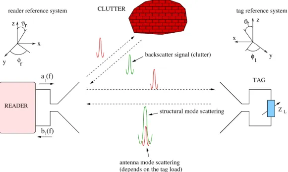
1.6 Multi-reader scenario with tags and scatterers placed in the environment. . . 17
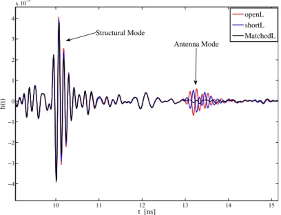
1.7 Structural and antenna modes measured in an anechoic chamber. 18 1.8 Antenna mode scattering contribution. . . 19
1.9 The internal logistics of a manufacturing plant [15]. . . 20
2.1 Ideal reader (left) and tag (right) antennas in LOS. . . 24
2.2 Left: Ideal reader antenna (transmitting) and tag antenna (receiving) in LOS. Right: Ideal reader antenna (receiving) and tag antenna (transmitting) in LOS. . . 24
2.3 Tag electric scheme. . . 28
2.4 Summary scheme of the methodologies proposed. . . 29
2.5 Dipole in proximity to a metal plate. . . 30
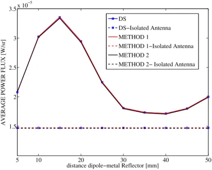
2.6 Average backscattered power flux vs. tag/metal plate dis-tance. DS refers to the reference simulation. . . 31
2.7 Simulated dipole in front of a metal plate. . . 33
2.8 Total Backscattered power over the sphere vs tag/metal plate distance. DS refers to the reference simulation. . . 34
2.9 Ideal reader antenna (receiving) and tag antenna (transmit-ting) in LOS. . . 35
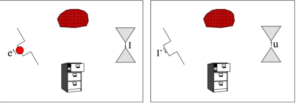
2.10 Left: Ideal reader antenna (transmitting) and tag antenna (receiving) in LOS and in presence of scatterers. Right: Ideal reader antenna (receiving) and tag antenna (transmitting) in
LOS and in presence of scatterers. . . 35
2.11 Left: Reader side for configuration of Fig. 2.10 on the right. Right: Tag side for configuration of Fig. 2.10 on the left. . . . 36
2.12 Sketch of the 2-ports system. . . 38
2.13 Simulated scenario. . . 41
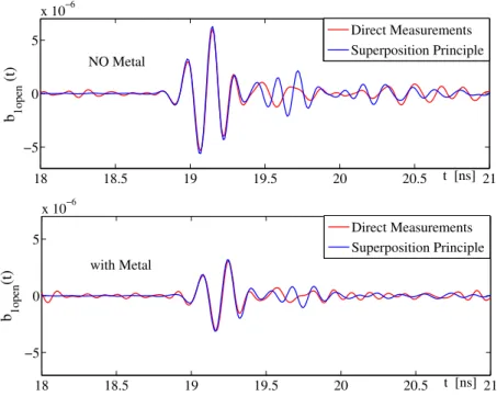
2.14 Left: complete received signal (b1Open). Right: Comparison between direct simulations and use of the superposition prin-ciple adopting method 1. . . 42
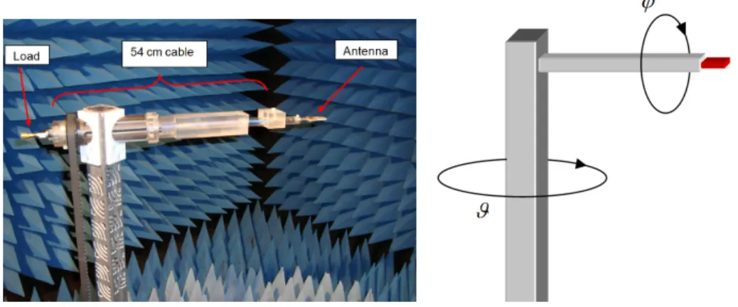
2.15 Measurement set-up inside the anechoic chamber. . . 42
2.16 Measurement results. Method 1 is adopted for the superposi-tion principle. . . 43
2.17 Reader tag configuration. . . 44
3.1 Measurement scenario . . . 48
3.2 Left: Antenna connection and support configuration. Right: Measurement system rotations. . . 49
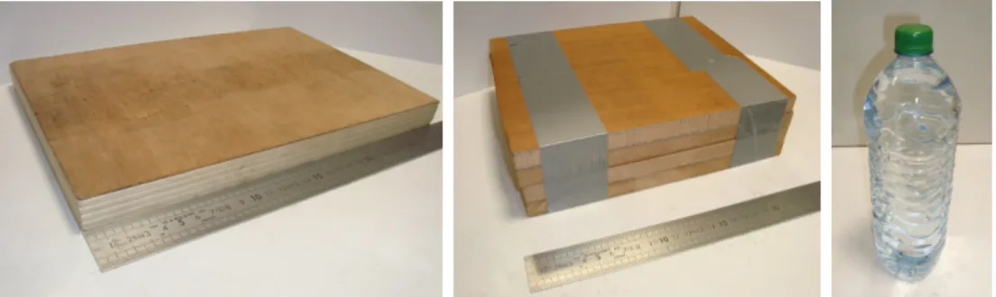
3.3 Left: 22 mm plywood block. Middle: 64 mm composite wood block. Right: plastic bottle full of tap water. . . 51
3.4 Paper block composition . . . 51
3.5 Wood panel in proximity of the tag antenna for ϕ = 0. . . 52
3.6 a) ϕ = 0◦. b) ϕ = 90◦ c) ϕ = 270◦. . . 53
3.7 Linear normalized antenna mode tag backscattering gain for different antennas in the azimuth plane. The maximum mea-sured isolated Antenna Mode tag backscattering values are in dB: Dual Feed Monopole Monostrip (DFMM)=-0.94. monopole dual feed stripline antenna (DFMS)=2.31. SLOT=7.99. Pla-nar balance dipole (PBD)=5.32. . . 54
3.8 |S11| for the DFMM antenna. . . 55
3.9 |S11| for the DFMS antenna. . . 55
3.10 |S11| for the SLOT antenna. . . 56
3.11 |S11| for the PBD antenna. . . 56
3.12 Left: Average tag backscattering gain cumulative distribu-tion funcdistribu-tion (CDF)s concerning the antenna mode scattering. Right: Average tag backscattering gain CDFs concerning the structural mode scattering. . . 57
3.13 Ideal reader antenna (receiving) and tag antenna (transmit-ting) in LOS. . . 59
3.14 Top: Service coverage analysis for Nr = 1 (left), Nr = 2 (mid-dle) and Nr ≥ 3 (right). Bottom: same conditions of the top, with a boost of 10 dB in the transmitted power. . . 60
3.15 Service coverage analysis Nr = 1 and SNRth = −25 dB. Top:
DFMS with wood of thickness 22 mm (left) and wood of thick-ness 64 mm (right). Bottom: DFMS with paper and with bot-tle of water (right). . . 61
3.16 Service coverage analysis Nr = 2 and SNRth = −25 dB. Top:
DFMS with wood of thickness 22 mm (left) and wood of thick-ness 64 mm (right). Bottom: DFMS with paper and with bot-tle of water (right). . . 62 3.17 Service coverage analysis for Nr= 2 (middle) and power boost
of 10 dB. Top: Isolated antennas. Middle: Antennas with
wood of thickness 22 mm. Bottom: antennas with bottle.
DFMM (left), SLOT (middle) and PBD (right). . . 63
3.18 Measured antennas in presence of a metallic reflector. . . 64 3.19 ultrawide-band (UWB) thick dipole in the presence of a metal
plate with dimensions (5 × 5) cm2. . . . 65
3.20 Top: Measured Antenna mode scattering with 10x10 cm2metal
placed 1 cm behind the DFMS. Bottom: isolated antenna case. 66 3.21 Left: simulated DFMM. Right: simulated thick broadband
dipole. . . 66
3.22 Metal can placed behind the planar UWB dipole. . . 67
3.23 Simulated antenna mode scattering for the planar dipole. . . . 67
3.24 Average backscattered energy over the azimuth plane (mea-sured DFMS). . . 68 3.25 Top: Simulated average energy over the azimuth plane for the
DFMM. Bottom: Measured average energy over the azimuth plane for the DFMM. . . 68 3.26 Top: Simulated average energy over the azimuth plane for the
dipole. Bottom: Measured Average energy over the azimuth plane for the dipole. . . 69 3.27 Top: 3-D mean realized gain for isolated dipole (left) and with
a plate (10 × 10 cm2) behind (right). Bottom: mean realized gain over the azimuth plane for isolated dipole and in presence of metals. . . 71 3.28 Left: total backscattered power over the sphere vs tag/metal
plate distance. Right: Average 3D power flux. . . 73 4.1 Multi-reader scenario with Ntag tags. . . 76
4.2 Reader ultra-high frequency (UHF) and UWB transmitted sig-nals. . . 77
4.3 The UWB interrogation signal structure. . . 78
4.4 Example of reader internal structure. . . 79 4.5 Tag internal structure. . . 80
4.6 Wake-up synchronization procedure. . . 82
4.7 Received signal amplitude [V ]. Concerning interference from
other readers, different cell sizes are considered. . . 84
4.8 Received signal amplitude [V ], where quantization steps
plitudes are associated to different m. Interfering reader am-plitude and quantization levels related to a (10×10) m2 square cell. . . 85 4.9 SQNRin at the de-spreader input for a 10 × 10 m2 square cell,
as a function of useful tag distance, reported for different m. . 86 4.10 The considered clock skew model. . . 88
4.11 Clock drift effects on passive and active communication. . . . 90
4.12 Parallel de-spreading blocks. . . 91 4.13 Interference scenario. . . 97 5.1 Reader internal structure. . . 102 5.2 Tag detection scheme. . . 104
5.3 Example of energy matrix E in presence of wake-up offset,
clock drift and near-far interference effect. . . 106
5.4 Minimum number of pulses per symbol as function of the
reader-tag distance. . . 113
5.5 receiver operating characteristic (ROC) for tag detection in
UWB backscatter system. Continuous lines (–) refer to the perfectly synchronous scenario, dashed lines (- -) refer to the asynchronous scenario, with ideal code phase retrieving. . . 115
5.6 ROC for tag detection in UWB backscatter system, when
or-thogonal Gold codes are adopted in presence of tag clock drift and code acquisition schemes in a quasi-synchronous scenario. Continuous lines (–) refer to Nc= 128, dashed lines (- -) refer to Nc= 1024. . . 116
5.7 ROC for tag detection in presence of synchronization offset,
clock drift and near-far interference effects. Continuous lines (–) refer to the bin-dependent threshold, dashed lines (- -) refer to the constant threshold. . . 118 6.1 The behavior of the signals described in Sec. 6.2. . . 123 6.2 Clutter removal after signal de-spreading. . . 125
6.3 Grid considered for the measurement campaign at ENSTA-ParisTech. The distances between each point and the antennas connected to the vector network analyzer are also reported. . . 128
6.4 Indoor scenario considered for the measurement campaign at
ENSTA-ParisTech. . . 129 6.5 Example of backscatter responses collected inside in the
ane-choic chamber (plot a) at distance dref = 1.46 m, in the labora-tory (plot b) grid location H at distance of 3.10 m, and of the only antenna mode contribution after clutter removal (plot c) in the same location H. . . 130 6.6 BEP as a function of the bit rate Rb in different tag locations
(Laboratory scenario). The SPMF receiver is considered. . . . 132 6.7 BEP as a function of the bit rate Rb in different tag locations
(Laboratory scenario). The IMF receiver is considered. . . 133
6.8 BER as a function of the SIR in the anechoic chamber
sce-nario where clutter is summed up artificially. DFMS antenna considered. . . 134
6.9 BER vs Ns in multi-tag laboratory environment and
asyn-chronous scenario. . . 135 6.10 BER vs Ns in multipath 802.15.4a CM1 channel. . . 137
A.1 The considered scheme for the ADC and despreader. . . 144
A.2 signal-to-quantization-noise ratio (SQNR) at the output of the de-spreader-accumulator, for low signal-to-noise ratio (SNR). . 146 A.3 SQNRout as a function of Ns, for high SNR. . . 147
A.4 Relation between SQNRout and SQNRin, for high SNR. . . 148
B.1 Double/triple cross-correlations when orthogonal Gold Codes (Nc = 128) are assigned to the readers and to the tags. . . 151
List of Tables
1.1 Comparison among the different operative RFID frequencies. . 9
2.1 Average % error on the backscattered power for each method
with respect to direct simulations. . . 32 3.1 Antennas and descriptions . . . 50
4.1 Clutter rejection and process gain properties of odd codes. . . 92
List of Acronyms
ACF autocorrelation function ADC analog-to-digital converter ASK amplitude shift keying AUT antenna under test
Auto-ID automatic identification AWGN additive white Gaussian noise BEP bit error probability
BER bit error rate
BPSK binary phase shift keying CCF cross correlation function
CDF cumulative distribution function CDMA code division multiple access CIR channel impulse response
CR channel response CS clock skew
CW continuous wave
DFMM Dual Feed Monopole Monostrip DFMS monopole dual feed stripline antenna ED energy detector
EEPROM Electrically Erasable Programmable Read-Only-Memory EIRP effective radiated isotropic power
ELP equivalent low-pass EM electromagnetic EU European Union
PFA probability of false alarm
FCC Federal Communications Commission FSK frequency shift keying
HF high frequencies HW hardware
IDT interdigital transducer IMF ideal matched filter INR interference-to-noise ratio IR-UWB impulse radio UWB IR impulse radio
ISNR interference-plus-signal-to-noise-ratio LF low frequencies
LNA low-noise amplifier LOS line-of-sight
MAC medium access control MUI multi-user interference NPF normalized power flux OC open circuit
OFDM orthogonal frequency division multiplexing p.d.f. probability distribution function
PBD Planar balance dipole PD probability of detection PN pseudo-noise
PPM pulse position modulation PRP pulse repetition period PSD power spectral density PSK phase shift keying
QAM quadrature amplitude modulation r.v. random variable
RCS radar cross section RF radio-frequency
RFID radio-frequency identification ROC receiver operating characteristic RRC root raised cosine
RTLS real time locating systems SAW surface acoustic wave SC short circuit
SCM supply chain management SCR signal-to-clutter ratio SIR signal-to-interference ratio SNR signal-to-noise ratio
SPMF single-path matched filter
SQNR signal-to-quantization-noise ratio SRAM static random access memory SS spread spectrum
TDMA time division multiple access TH time-hopping
TOA time-of-arrival UHF ultra-high frequency UWB ultrawide-band
VNA vector network analyzer WSN wireless sensor network
Introduction
The recent idea of the “Internet of Things”, a pervasive presence of electronics devices embedded in every-day objects, is facing a rapid adoption and will create a new era in the Internet scenario. Ideally, it is expected that every object in our every-day life will be assigned to an IP address and will be sensitive and responsive to the presence of people [1–4].
Considering working and domestic fields, a few possible application sce-narios will be domotics, assisted living, e-health and enhanced learning. Sim-ilarly, from the perspective of business users, the most apparent consequences will be equally visible in fields such as automation and industrial manufac-turing, logistics, business/process management, intelligent transportation of people and goods [5].
Nowadays, a significant number of industrial realities have moved towards the so-called supply chain management (SCM) approach [6], relying on the administration of the various logistics activities of the companies. One of the main requirements of this approach is the knowledge of what a given object is and where it can be found at a given temporal instant. The adop-tion of automatic identificaadop-tion (Auto-ID) systems for the identificaadop-tion of the goods is widely diffuse, usually exploiting barcode reading or standard RFID tags. These approaches excel in answering the question regarding an item identity, but fail at providing its position to the users. On the con-trary, real time locating systems (RTLS) offer an expensive high-precision localization solution, but are not usually integrated with Auto-ID standards. These novel systems are composed of a certain number of readers or anchor nodes interrogating tags deployed in a given area, in order to obtain data stored on them as well as localize the objects they are attached to. Existing RFID systems in SCM employ active tags that periodically send signals to anchor nodes placed in strategic points of the warehouse. Despite ensuring a greater precision, the adoption of active tags, which are equipped with ac-tive transmitters, leads to an increased price of the network and to a reduced battery life, causing an increased cost of the overall system and its mainte-nance. These drawbacks represent significant limitations to the adoption of
active tags in RFID and RTLS, and passive or semi-passive solutions become a good alternative to overcome such a limitation, as the energy necessary for tag-reader communication is harvested from the reader’s signal or the sur-rounding environment [7]. Communication with passive tags usually relies on backscatter modulation, where the antenna reflection properties are changed according to information data, avoiding the need of a transmitter.
In order to achieve a sub-meter level precision, the majority of current RTLS solutions rely on UWB signals [8, 9]. The adoption of UWB pulses in conjunction with ranging techniques [10, 11], allows sub-nanosecond time resolution, which significantly enhances the localization precision with re-spect to other radio technologies. Recently it has been shown that impulse radio (IR)-UWB is a very promising technique, which could meet the strin-gent requirements of passive tag localization in terms of accuracy [12]. The advantage of such a technology is to provide the typical accuracy of UWB-RTLS by employing a very simple tag, based on a backscattering modulation instead of using a complete UWB active transmitter. However one of the most important issues in these systems is the energy supply as no sufficient energy can be transfered through UWB signals due to severe regulating lim-itations in the emission mask. Combining UWB (semi-)passive RFID with already existing UHF technologies is a possible approach, either through en-ergy harvesting [13] or through the implementation of a wake-up technique in order to increase the battery lifetime. Moreover the UHF module can be employed to ensure compatibility with already existing RFID systems. These technologies are also proposed and studied in the European project SELECT, which is briefly described in Sec. 1.8.
In this context, from a real and urgent necessity to overcome the main limitations of actual RFID technology adopted in industrial environments, the present thesis aims to study from different perspectives a UWB semi-passive RFID system, based on backscatter modulation. The design of ro-bust backscatter communication scheme requires the comprehension of the electromagnetic (EM) aspects involved in the backscattering mechanism. In addition, simulated and measured UWB RFID backscattering data can be exploited for the validation of the proposed system design, in order to eval-uate system performance in terms of detection and communication range. For this reason, the need to combine these different aspects has motivated a joint work between two laboratories associated with Ecole Polytechnique and University of Bologna, having a strong background in the complementary competences necessary for a deep investigation on the thesis subject.
The manuscript is organized as follows.
Chapter 1 introduces the basic concept of the UWB and RFID tech-nologies and provides an up-to-date bibliography on the topic. The main
motivations of the work are explained.
Chapter 2 is dedicated to the study of the antenna backscattering physics, using the superposition and the reciprocity principles. An alternative method-ology to link the tag transfer function with the backscattered response is also described, this relation being exploited in the following chapters.
Chapter 3 concerns the characterization of the interaction between an UWB RFID antenna and a close disturber modifying the antenna radiation characteristics. Measurements are post-processed in order to assess the de-tection coverage of tags and see how the presence of an object behind a tag affects the probability that the tag itself is seen by the reader, considering all possible tag positions and orientations. Finally, the interaction of an UWB antenna with a metallic reflector, whose presence greatly affects the antenna radiation characteristics, is addressed.
Chapter 4 provides a reader-tag signaling structure, where the clock
drift problem and the quantization issue are modeled. A system architecture for mitigating the presence of multi-tag interference and strong clock drifts is also presented, jointly with the investigation of different spreading code design strategies.
In Chapter 5, the design of a system architecture capable of tag detection even in presence of multi-tag interference and strong clock drift is investi-gated, starting from the general system analysis conducted in Chapter 4. A low complexity non-coherent detection scheme is proposed and analyzed, by investigating the impact of different spreading codes on system performance. Specifically, the near-far interference problem, which derives from the semi-passive nature of the system, is addressed, and a solution to counteract this issue and guarantee robust tag detection is proposed.
Once the presence of a tag has been correctly revealed, reader-tag com-munication performance has to be assessed. Chapter 6 discusses the architec-ture of a system of tags and readers together with related signal processing schemes with the purpose to demodulate the payload contained in the tag memory even in the presence of multiple tags, starting from the considera-tions reported in Chapter 4. The system performance is simulated in terms of range/data rate trade-off, clutter suppression and multiple access capability, using experimental data collected both in ideal and real environments.
Finally, general conclusions assess the contributions carried out within this thesis and which are described in each chapter.
Author Contributions
The thesis activity has been conducted for about three years and a half, with interleaved periods spent in France and in Italy, in the context of the Euro-pean project SELECT, whose aims and perspectives are briefly described in Sec. 1.8
In particular, during the collaboration at Ecole Polytechnique, the anal-ysis of the tag backscattering has been analyzed in several ways, both in ideal and real conditions, starting from the previous works carried out in the laboratory (A. Sibille, C. Roblin and R. D’Errico). After the study and the proposal of some approaches to reconstruct the antenna backscattering by means of the superposition principle, simulations and measurements have been performed to assess the methodologies.
Further measurements and simulations campaigns have then been done to investigate the interaction of the tag antenna with a disturber placed in its proximity. While for current RFID technology many studies have been conducted on this topic, for UWB RFID the research was in its infancy. Apart from the case where a metallic object is considered, which has been studied specifically, the detection and localization coverage with other types of objects have been evaluated adopting measurement results.
During his work at University of Bologna, the author participated with other participants of the SELECT consortium in finding reliable solutions for the design of ad hoc and robust UWB RFID system architecture. This part of the thesis has mainly been carried out in collaboration with Davide Dar-dari and Nicol`o Decarli and has focused on signal processing techniques and practical solutions to overcome hardware (HW) limitations and implementa-tions issues. Part of the analyses carried out within the project is detailed in Chapter 4 and has been reported in the technical reports listed below.
During the periods spent at University of Bologna, A proper reader and tag architecture based on UWB backscatter modulation has been analyzed, starting from the model proposed by Dardari and D’Errico in [14]. A low-complexity detection and synchronization scheme involving bin-dependent thresholding has also been proposed in order to overcome implementation
impairments and near-far effects, as in the literature no studies were avail-able to cope with these problems, at the best of the authors knowledge. The system performance has been evaluated considering different scenar-ios in terms of detection and false alarm rate, involving the analysis of the robustness of different code families in different scenarios, and when code ac-quisition schemes are adopted to counteract the presence of strong tag clock drift. The performance of the proposed architecture has been also assessed in terms of range/data rate trade-off, clutter suppression and multiple access capability.
The obtained results have been published in journal papers and in the proceedings of international conferences, which are listed below.
List of publications
Journal papers
• D. Dardari, F. Guidi, C. Roblin, and A. Sibille, ”Ultra-wide band-width backscatter modulation: Processing schemes and performance,” EURASIP Journal on Wireless Communications and Networking, no. 1, 2011.
• N. Decarli, F. Guidi, D. Dardari, ”A novel joint RFID and radar sen-sor network for passive localization: design and performance bounds,” submitted to IEEE Journal on Selected Topics in Signal Processing. • F. Guidi, A. Sibille, D. Dardari, C. Roblin, ”Impact of Tag
Backscat-tering Characteristics on the Detection Coverage,” submitted to IEEE Trans. On Antennas and Propagations.
• F. Guidi, N. Decarli, S. Bartoletti, A. Conti, D. Dardari, ”Robust detec-tion of UWB backscatter signals in multi-tag environment,” submitted to IEEE Trans. On Wireless Communications.
Conference papers
• F. Guidi, D. Dardari, C. Roblin, and A. Sibille, ”Backscatter commu-nication using ultrawide bandwidth signals for RFID applications,” in D. Giusto et al. (eds.), The Internet of Things: 20th Tyrrhenian Work-shop on Digital Communications SpringerScience+BusinessMedia , Pula, Sardinia, ITALY, Sep. 2009, pp. 251262
• F. Guidi, M. Sacko, A. Sibille, and C. Roblin,”Electromagnetic analysis of RFID tag backscattering,” in JNCW, 2011, Paris, France, 2011 • F. Guidi, A. Sibille, D. Dardari, and C. Roblin, ”UWB RFID
and Propagation (EUCAP), Proceedings of the 5th European Confer-ence on, april 2011, pp. 1425 1429
• F. Guidi, M. Sacko, A. Sibille, and C. Roblin, ”Analysis of UWB RFID tag backscattering in the presence of scatterers,” in General Assembly and Scientific Symposium, 2011 XXXth URSI, aug. 2011, pp. 1 4 • F. Guidi N. Decarli, D. Dardari, C. Roblin, A. Sibille, ”Performance of
UWB backscatter modulation in multi-tag RFID scenario using exper-imental data,” in Proc. of the 2011 IEEE International Conference on Ultra-Wideband (ICUWB 2011) , Bologna, Italy, Sep. 2011.
• A. Sibille, M. Sacko, Z. Mhanna, F. Guidi, and C. Roblin: ”Joint antenna-channel statistical modelling of UWB backscattering RFID,” in Proc. of the 2011 IEEE International Conference on Ultra-Wideband (ICUWB 2011), Bologna, Italy, Sep. 2011.
• N. Decarli, F. Guidi, A. Conti, D. Dardari, ”Interference and clock drift effects in UWB RFID systems using backscatter modulation,” in Proc. of the IEEE International Conference on Ultra Wideband, (ICUWB 2012), Syracuse, New York, USA, Sep. 2012.
• R. D’Errico, M. Bottazzi, F. Natali, E. Savioli, S. Bartoletti, A. Conti, D. Dardari, N. Decarli, F. Guidi, F. Dehmas, L. Ouvry, U. Alvarado, N. Hadaschik, C. Frankek, A. Zhangk,. Mhanna, M. Sacko, Y. Wei, A. Sibille, ”An UWB-UHF semi-passive RFID system for localization and tracking applications,” in Proc. of the IEEE International Conference on RFID-Technology and Applications (RFID-TA 2012), Nice, France, Nov. 2012.
• E. Savioli, M. Bottazzi, F. Natali, N. Decarli, F. Guidi, N. Hadaschik, R. D’Errico, L. Ouvry, ”Semi-passive UHF-UWB RFID: architecture and localization performance,” in Proc. of the IEEE International Con-ference on Communications (ICC 2013) .
Technical reports
• F. Guidi, N. Decarli, A. Guerra, V. Casadei, S. Bartoletti, M. Guerra, C. La Palombara, A. Conti, D. Dardari, N. Hadaschik, R. D’Errico, L. Ouvry, F. Dehmas, A. Sibille, C. Roblin: SELECT Deliverable D2.3.2, ”Multi-functional network design: final system specification,” Jun. 2012.
• D. Dardari, A. Conti, N. Decarli, S. Bartoletti, V. Casadei, M. Guerra, A. Mariani, A. Giorgetti, A. Sibille, F. Guidi, F. Dehmas, R. D’Errico: SELECT Deliverable D2.2.2, ”Signal Processing techniques: final re-port,” Apr. 2012.
• A. Sibille, C. Roblin, D. Dardari, A. Conti, N. Decarli, F. Guidi, N. Hadaschik, T. Nowak, F. Natali, E. Savioli, M. Bottazzi: SELECT De-liverable D2.3.1, ”Multi-functional network design: intermediate sys-tem specification,” Sep. 2011.
• D. Dardari, A. Conti, N. Decarli, S. Bartoletti, V. Casadei, M. Guerra, A. Mariani, A. Sibille, F. Guidi, F. Dehmas, V. Heiries, R. D’Errico: SELECT Deliverable D2.2.1, ”Signal Processing techniques: interim report,” Jul. 2011.
• C. Roblin, A. Sibille, F. Guidi, M. Sacko, Z. Mhanna, R. D’Errico, V. Heiries, J. Keignart, D. Dardari, N. Decarli: SELECT Deliverable D2.1.1, ”Backscatter propagation modeling: interim report,” Jul. 2011.
Chapter 1
State of the art of RFID and
UWB Technologies
1.1
Introduction
This chapter briefly describes the RFID and the UWB technologies, with a particular perspective on the main limitations of the current adopted tech-nologies, and on the advantages carried out by the joint use of UWB with RFID. Some of the latest works on this topic are here referenced, with an emphasis on the subjects where the thesis aims to bring a novel contribution. Within this context, the European project SELECT [15] is shortly reported. It has enriched the inter-disciplinarity of the work and also has led to face some of the practical issues that arise in industrial scenarios.
1.2
The RFID Concept
The concept of the “Internet of Things”, defined by the MIT Auto-ID Labs, is expected to introduce a new era where the physical world will be mapped into the internet space, thus enabling a potentially huge number of novel applications [1–4]. Ideally, it is expected that every object in our every-day life will be assigned to an IP address and will be sensitive and responsive to the presence of people. From the technological point of view, a key en-abling technology is represented by RFID [16–26]. In recent years, the RFID technology has become a common occurrence in every day life. It is mainly used for real time identification of objects, and the development of RFID systems is due to the fact they do not need line of sight visibility, as happens in other communication systems such as bar codes, or physical contact which is also need by several other technologies. In fact, a RFID system consists of
readers and tags located on objects, where the readers interrogate the tags via a wireless link in order to obtain the data stored on these tags [27]. The maximum distance between the data carrier and the reader can be a few meters, the communication being based on radio-frequency signals [28].
The RFID technology was first introduced in the second World War to identify aircraft and it was called Identity-friend or foe; later in the decade, Vinding developed (January 1967) a simple and inexpensive interrogator-transponder system based on inductive coupling, [7]. As soon as the prices of RFID dropped, the industry started using them in many applications. For instance since 1979 it has been in use to identify and track animals. In 1994 all rail cars in the United States used RFID for identification [29] and today this promising technology has been applied to a huge variety of fields such as [28]:
• managing vehicle fleets;
• increasing highway throughput;
• speeding up transactions at the point of sale; • gaining entrance to buildings;
• shipping containers;
• identifying livestock and pets; • and many other fields.
Nowadays, there is a growing interest in the convergence of RFID and high accuracy RTLS technologies to enhance the functionalities offered to the end user and enable new potential wide market applications [12, 30, 31]. Figure 4.1 shows an example of RFID-RTLS network where some interroga-tors, placed in a controlled environment, monitor a certain area to detect and localize tagged people and objects present in the scenario. In fact, future ad-vanced RFID systems are expected to provide both reliable identification and high accuracy localization of tags at submeter level. Thus, new im-portant requirements, such as accurate real-time localization, high security, large numbers of tag management, in addition to extremely low power con-sumption, small size, and low cost, will be mandatory [17]. Unfortunately, most of these requirements cannot be fulfilled completely by the current first and second generation RFID or wireless sensor network (WSN) technologies, such as those based on ZigBee standard [24, 32].
In fact, RFID systems using standard continuous wave (CW)-oriented communication in the UHF band have an insufficient range resolution to
Untagged Person (Clutter) Tagged Object Tagged Object/Person Clutter Reference Node
Figure 1.1: Example of a scenario with some reference nodes and tagged and untagged objects.
achieve accurate localization, are affected by multipath signal cancellation (due to the extreme narrow bandwidth signal), are very sensitive to nar-rowband interference and multi-user interference, and have an intrinsic low security [18, 20, 22, 28, 33, 34]. Although some of these limitations, such as security and signal cancellation due to multipath, are going to be reduced or overcome in future versions of UHF RFID systems [23, 35], a technology change is required to fully satisfy new applications requirements, especially those related to high-definition localization at the submeter level [36, 37].
In the following, the RFID technology is described and possible solutions to overcome current system limitations are detailed. Particular emphasis is put on the motivations of the present thesis, which arise in the described context of interest.
1.3
Main Characteristics of RFID Systems
and Technologies
The RFID system is composed of respectively one or more readers and tags according to the specific purpose. Figure 1.2 shows an example of a scenario composed of a reader, which interrogates tags located in the same area. There
Reader
Tag
Tag
Tag
Tag
Figure 1.2: Classic RFID scenario with a reader interrogating several tags em-ployed in the scenario.
are numerous methods of extracting the information stored in the tag, like the modulation of the backscattered signal or the generation of another signal by the tag itself, depending on whether it is passive (semi-passive) or active. The reader, or interrogator, is usually constituted of a control unit, a memory, a radio frequency module (transmitter and receiver) and a coupling element (like an antenna) as it should guarantee three main functions: en-ergizing, demodulating and decoding. The control unit commonly contains one or more processors and ”controls” the operations of the reader; it exe-cutes the software instructions stored in the memory. The transmitter has the function to generate the signal that is sent through the coupling element to the tag. Then the receiver probes the environment to collect the received signal from the interrogated devices; its design often includes a low-noise amplifier (LNA) and in some cases also two separate antennas, dedicated for signal transmission and reception. In addition, the coexistence of the trans-mitter and the receiver is managed by a circulator, allowing to separate the transmitted and received signals. The reader also has an additional interface enabling the communication with an external controller, such as a PC [28].
For what tags are concerned, they actually represent the data-carrying device of the RFID system and they basically consist of a coupling element,
interacting with the reader, and a microchip. There are different ways for the tag to transmit back the information to the reader, according to the fact it is active, semi-passive or passive, which are strictly related to the internal structure of the transponder. In the following, the tag categories are distinguished and their main features are analyzed.
1.3.1
Active Tags
Active tags are usually fed by their own battery and their internal structure is similar to the reader, being full-fledged radios equipped with a battery, receiver, transmitter, a memory and a control circuitry. The tag generates a carrier signal using a local oscillator and a crystal reference, so that it can apply different kind of modulations, like amplitude shift keying (ASK), phase shift keying (PSK) or frequency shift keying (FSK), quadrature amplitude modulation (QAM), etc.
Since active tags have a significant amount of energy provided by the battery, large operating ranges are achievable and big memories like static random access memory (SRAM), suited for both reading and writing, are often integrated. In active tags there is also the possibility to integrate sen-sors in order to monitor the surrounding environment. Current studies are directed towards decreasing the power consumption, since the device opera-tion lifetime is strictly related to the duraopera-tion of the battery. A promising perspective is to harvests energy from the environment (i.e. photovoltaic cells) in order to guarantee a continuous power supply and a recharging of the battery [38, 39].
1.3.2
Passive and Semi-Passive Tags
When the cost, size, and power consumption requirements of RFID tags become particularly stringent, passive or semi-passive ones have the largest commercial potential, the energy necessary for tag-reader communication being harvested from the reader’s signal or the surrounding environment [7]. Since the feeding system is usually off, passive tags are generally equipped with a nonvolatile memory like Electrically Erasable Programmable Read-Only-Memory (EEPROM), which have smaller dimensions than active tag memories [38, 39]. The downside of the coin is that the lack of a battery to feed the tag signal prevents operating at the same high distances as active tags.
Communication with passive tags usually relies on backscatter modula-tion, where the antenna reflection properties are changed according to infor-mation data, avoiding the need of a transmitter. In fact, specific variations
Figure 1.3: Magnetic field in a coil [28].
of the load create a code sequence that identifies the object where the tag is attached. In particular, the antenna interacts with the incident electromag-netic fields, producing a high-frequency voltage. Then the voltage is rectified by a diode and the final signal is smoothed using a storage capacitor. The intent is to obtain a constant voltage to feed the tag’s logic circuitry and memory access. Two different ways of interaction between the reader and the tag are used: near field coupling and far-field coupling [7].
Near-field coupling The EM field in the near-field region is reactive in
nature, and the electric and magnetic fields are orthogonal and quasi-static. A field dominates the other one according to the kind of the antenna adopted in the application: if a coil is considered, the magnetic is prevalent on the electric field, whereas the contrary happens if a generic dipole is considered. Most near-field tags rely on the magnetic field through inductive coupling in the tag coil and this principle is based upon Faraday’s principle law [7]. In the general form, this principle can be stated as follows: ”the contour integral of magnetic field strength H along a closed curve is equal to the sum of the current strengths I of the currents within it” [28, 40]
X I =
I −→
H ·−→d s . (1.1)
Then, (1.1) can be used to evaluate H for different conductors. Consider a straight conductor: the field strength H along a circular f lux line at dis-tance equal to r is constant and it is expressed in the following way [28]:
H = 1
2πr . (1.2)
A rectilinear conductor is not suited to induce a current in the components of a RFID system; once the distance r is fixed, the field is constant. For this reason cylindrical coil antennas are used in the RFID applications where magnetic coupling is the basic principle exploited to communicate. The path of field strength along the axis of the radius of the coil is given by
H = I · N · R
2
2p(R2+ x2)3 (1.3)
where N is the number of windings, R is the circle radius and x is the dis-tance from the centre of the coil in the x direction [28]. At disdis-tance 0, that is, in the center of the antenna, (1.3) becomes:
H = I · N
2R . (1.4)
In passive and semi-passive tags, the communication is usually based upon load modulation: each load variation causes a change of the current in the tag, which generates itself a small current variation at the reader side due to the mutual inductance. Tag information data can thus be extrapolated by the reader through a proper ”reading” of these current fluctuations at its side.
For this kind of interaction, low carrier frequencies are adopted: for ex-ample, the two most common ones are 128 kHz in the low frequencies (LF) and 13.56 MHz on the high frequencies (HF) side, with a boundary distance of respectively 372 m and 3.5 m. In these conditions, there is the necessity to adopt large antenna coils, and the use of a magnetic dipole is not convenient because its magnetic field in the near-field region drops as 1/d6 where d is the reader-tag distance. There is also a boundary between near-field and far-field regions, which is about 2D2/λ, where c is the light speed [7].
Far-field coupling Due to the mutual dependence of the time varying
fields, there is a chain effect of electric field and magnetic fields in space [28] which propagates with the light speed (≈ 3 · 108m/s). This concept is explained by the Faraday’s law, given by
∇ ×−→E = −∂ − → H
As the magnetic field strength rapidly decays when the electromagnetic wave travels in the space away from the antenna, the EM field in the condi-tion of far-field is radiative in nature. The EM waves propagate until they encounter the tag, and if its dimensions are equal to or bigger than a half wavelength of the EM wave, the incident signal gets reflected. The amount of the reflected signal partially depends on the impedance mismatch between the antenna and the load circuit: variations of the load affect backscattered signal, hence they can be used to carry information data.
For far-field coupling there is no boundary (as a difference for near field) and this technique is usually adopted for long range (5 − 20 m). Another advantage is related to the attenuation during the trip of the wave, as for near field it is in the order of 1/d6, while in this case the attenuation is proportional to d2. Usually far-field tags operate in the band 860 − 960 MHz (UHF) and in the 2.45 GHz Microwave band [7] and they adopt different sizes and shapes according to the application requirements. Unfortunately, one of the problems in operating at frequencies greater than 100 MHz is the interaction between the EM waves and the surrounding environment. Mitigating it is one important parts of the present thesis work.
1.3.3
SAW Tags
There is another completely different interaction in RFID communication that exploits the conversion of EM wave in a nanoscale surface acoustic wave (SAW). In fact, in the presence of SAW tags, the reader transmits a radio wave pulse that is directly converted into a nanoscale SAW by an interdigital transducer (IDT) put on a surface chip. Then this signal travels on the surface of the SAW chip and it encounters a set of wave reflectors that create a precise sequence of acoustic wave pulses, which subsequently travels back to the IDT. These pulses are converted into an encoded radio wave reply signal that is backscattered to the reader. A great advantage of this technique is the absence of the DC power, as a piezoelectric effect is exploited. In the beginning, the interest for SAW was very low due to the higher costs than traditional technologies like silicon-based RFID tags. Recent improvements, such as more precision with the phase weighting of the reflectors and more accurate control in the parasitic effects, led to an increase of the global interest for SAW tags [41, 42]. It must also be taken into account that there is a longer read range in the presence of water and metallic objects, guaranteeing a more reliable performance [7].
Table 1.1: Comparison among the different operative RFID frequencies.
Type frequency
Freq. range Read
range
Memory
Microwave 2.45 GHz 2m at best less than 1kbit
UHF 865 to 960 MHz
or 915 MHz
(US)
6m or more more than 1kbit
HF 3 to 30MHz
(usually 13.56MHz)
1.5m at best 256 bit to 8×32 bit blocks, 4 kByte addi-tional data memory available
LF 30KHz
to 300KHz
1m at best 64 bits to 1360bits
1.4
Summary of the Main RFID Tag
Char-acteristics
RFID systems usually operate at microwave, UHF, HF and LF frequencies. In the case of microwaves (i.e, 2.45 GHz), the read range is smaller than 2 me-ters, due to power link budget constraints. Usually the memories integrated in the structure of the tag are less than 1 kbit [7, 43, 44].
For UHF instead, RFID devices typically operate at the frequencies of 865 MHz and 960 MHz, apart from U.S. deployments in which it is 915 MHz. The read range is greater than 6 meters, according to the regulatory require-ments (4 Watt in U.S. and only 2 in Europe for the emitted power). In particular, the european UHF band between 865 MHz and 868 MHz is com-posed of 15 channels of 200 kHz each. Integrated memories can be equal to or greater than 1 kbit, the communication is faster (higher bit-rate) than for lower frequencies, and larger distances can be achieved. A limitation of UHF is the lack of global compatibility, since the spectrum allocation varies in the different countries.
For LF and HF there is no restriction for the emitted power and their spectrum is allocated in the same way all over the world. Considering HF, the frequency ranges from 3 MHz to 30 MHz (usually 13.56 MHz) and the
maximum distance between reader and tag is 1.5 m. Near-field coupling is usually exploited between transmitter and receiver, and memories of 256 bit to 8×32 bit blocks or data memory of 4 kB are used at these frequencies.
LF devices operate from 30 kHz to 300 kHz and most of the tags operate at 125 kHz with full duplex connection and 134 kHz with half duplex connection. The typical read range is 1 m (best performance), memories are very small (64 bits to 1360 bits) and the communication is very slow and without any anti-collision system. On the other side, it is the only technology that allows reading tags through water [7, 43].
1.5
Basic Features of UWB Technologies
As previously stated, a promising wireless technique for next generation RFID is the UWB technology. It is based, in its impulse radio UWB (IR-UWB) implementation, on the transmission of sub-nanosecond duration pulses [12]. Thanks to their low power consumption, IR-UWB transmitters can be adopted successfully for both active and passive tags. UWB has been proposed to implement low consumption and low complexity active radio-frequency (RF) tags for precision asset location systems [45].
The potential advantages of UWB include, but are not limited to, low power consumption at the transmitter side, extremely accurate ranging and positioning capability at the submeter level, robustness to multipath (bet-ter area coverage), low detection probability (higher security), and a large number of devices operating and co-existing in small areas (efficient multiple channel access and interference mitigation) [11, 22, 46–49]. Thus it is consid-ered a very promising technology with uniquely attractive features inviting major advances in wireless communication, networking, radar, imaging and positioning systems [49].
In the following, after a short history of UWB technology, the main fea-tures of this appealing technology are described.
1.5.1
UWB History
The first emissions of UWB signals are more than 100 years old and can be seen as a major milestone of modern radio, when Guglielmo Marconi sent the first UWB wireless pulses in 1901. Other contributes for developing this new concept came much later, starting from 1960 [50], when the specific ad-vantages of such signals were recognized. In 1960 the Lawrence Livermore National Laboratory (LLNL) and Los Alamos National Laboratory (LANL) conducted various researches on UWB transmitters and receivers. Cook and