HAL Id: hal-01184233
https://hal.archives-ouvertes.fr/hal-01184233
Submitted on 13 Aug 2015
HAL is a multi-disciplinary open access
archive for the deposit and dissemination of
sci-entific research documents, whether they are
pub-lished or not. The documents may come from
teaching and research institutions in France or
abroad, or from public or private research centers.
L’archive ouverte pluridisciplinaire HAL, est
destinée au dépôt et à la diffusion de documents
scientifiques de niveau recherche, publiés ou non,
émanant des établissements d’enseignement et de
recherche français ou étrangers, des laboratoires
publics ou privés.
Generic architecture for MPLS-TE routing
Imene Chaieb, Jean-Louis Le Roux, Bernard Cousin
To cite this version:
Imene Chaieb, Jean-Louis Le Roux, Bernard Cousin. Generic architecture for MPLS-TE routing.
4th International Conference on Communications, Internet, and Information Technology (CIIT 2006),
Nov 2006, St. Thomas, Virgin Islands, United States. pp.231-237. �hal-01184233�
GENERIC ARCHITECTURE FOR MPLS-TE ROUTING
Imene Chaieb and Jean-Louis Le RouxFrance Telecom R&D, Lannion 22307, France email: {imene.chaieb, jeanlouis.leroux}@orange-ft.com
Bernard Cousin IRISA, Rennes 35042, France email: bernard.cousin@irisa.fr ABSTRACT
This paper deals with Multi-Protocol Label Switching-Traffic Engineering Routing (MPLS-TE Routing) Systems which offer key Traffic Engineering features, including optimization of resources utilization, Quality-of-Service (QoS) and Fast Recovery. Numerous MPLS-TE Routing systems have been defined in the past with their own ad-vantages and drawbacks. This paper proposes a generic architecture for MPLS-TE Routing Systems, with the main objective of helping in classification, analysis and improve-ment of these systems or the design of new systems. This architecture includes main functions that may be required in an MPLS-TE Routing System. These functions and their interactions are described. Various approaches and options for the implementation and the distribution of these func-tions in network elements are qualitatively discussed. KEY WORDS
MPLS, Traffic Engineering, Routing, Quality-of-Service, Network Architecture
1 Introduction
The emergence of multi-service IP-centric networks, which transport value added services such as VoIP (Voice/Visio Telephony over IP), IP TV, Video on Demand and VPN traffics, leads to the requirements for strict QoS delivery (bounded delay, jitter, packet loss), and high availability. Given the huge increase of last miles capacities, and the re-duction of the gap between core and access bandwidth, the over-provisioning approaches followed for years by oper-ators in core and backhaul networks, so as to ensure the QoS, are no longer a panacea today in backhaul networks, and may no longer be a valuable approach in core net-works at mid term. Hence Traffic Engineering (TE) mech-anisms are required so as to optimize network resources utilization, that is to maximize the amount of traffic that can be transported, while ensuring the quality of service, with as main objective to reduce network costs and post-pone investments. In order to address the traffic increase and satisfy the QoS requirements of multimedia applica-tions, various TE mechanisms are proposed, among those MPLS-TE, a connection oriented mechanism based on the MPLS forwarding paradigm, well suited to TE thanks to its Explicit Routing capabilities. The MPLS-Traffic En-gineering approach [1] allows setting up explicitly routed Traffic Engineering-Label Switched Path (TE-LSP) whose
path satisfies a set of traffic engineering constraints, in-cluding bandwidth. MPLS-TE combines explicit routing capabilities of MPLS with a constraint based routing para-digm based on dynamic resources discovery (ISIS-TE [2], OSPF-TE [3]), constrained path computation, and distrib-uted LSP signalling and resources reservation (RSVP-TE) [4]. MPLS-TE ensures Traffic Engineering functions such as network resources optimization, strict QoS delivery, and fast recovery upon link or node failures. TE-LSPs can be used to route traffic flows between network Edge Routers. In order to efficiently route a set of flows in TE-LSPs, ad-ditional mechanisms are required on top of the standard MPLS-TE control plane. This includes essentially a TE-LSP utilization function, responsible for an efficient rout-ing of a set of flows in a set of TE-LSPs, along with an adaptability mechanism responsible for adapting the TE-LSPs topology (TE-LSPs resizing/creation/suppression) ac-cording to traffic matrix changes and/or topology changes (failures). These Utilization and Adaptability functions are actually intimately linked to the MPLS-TE Path Computa-tion funcComputa-tion. The combinaComputa-tion of the MPLS-TE control plane building blocks (Routing, Path Computation, Signal-ing) and these additional adaptability and utilization func-tions form together what we call a MPLS-TE Routing Sys-tem. In the literature, there are papers that focus on MPLS-TE path computation [5], [6], [7]. They propose efficient algorithms to place TE-LSPs in the network and satisfy a pre-defined set of flow requests. There are also studies which account for TE-LSPs utilization [8] and for adap-tation mechanisms [9]. Others, interest in flow admis-sion control and its application in MPLS-TE networks [10]. However, a global study that covers the overall architecture of an MPLS-TE Routing System is not considered. In the remainder of this paper, we firstly propose a generic archi-tecture to describe the functions of a MPLS-TE Routing System and their interaction, and then we give a qualitative analysis of some implementation options. The objectives of this Generic MPLS-TE Architecture are on the one hand to provide a common framework for classifying and analyz-ing existanalyz-ing MPLS-TE Routanalyz-ing Systems and on the other hand to help in improving existing systems or define new systems.
2 MPLS-TE Trunks and their Utilization
For a load balancing purpose, a set of two or more LSPs may be used to route a given aggregate traffic demand be-tween two end points. The TE-Trunk concept defined in
[11] allows accounting for such load balancing. A TE-Trunk is defined as a set of one or more LSPs used to carry an aggregate traffic demand between two points for a given service class. A TE-Trunk is characterized by its reserved bandwidth and a set of TE parameters (e.g. class of ser-vice, delay...). Note that for load balancing purposes, a set of two or more LSPs may be used to route a given aggre-gate traffic demand between two end points. The TE-Trunk concept allows accounting for such load balancing. When a TE-Trunk consists of more than one LSP, a load balanc-ing mechanism is required so as to select the LSP to be used to route a given flow. We distinguish today two main approaches for the deployment of TE-Trunks in Service Provider networks: The tactical approach and the strategic approach. The tactical approach consists in the deployment of a few TE-Trunks, so as to bypass some congested net-work segments. The strategic approach consists in meshing Edge Routers with a set of TE-Trunks. These TE-Trunks are used to carry all traffic or some specific traffic classes between Edge Routers. In the following, we focus on the strategic MPLS-TE approach.
In the strategic approach, TE-Trunks are initially computed using forecast traffic matrix, and then may be adapted in re-sponse to traffic changes or topology changes (e.g. network failures). Once these TE-Trunks are setup, they are used to route traffic flows between Edge Routers. As bandwidth reservation in MPLS-TE is purely logical, additional mech-anisms are required to ensure bandwidth guarantees. This requires policing mechanisms on Edge Routers so as to en-sure that the actual TE-Trunk load does not exceed the re-served bandwidth. Such policing can be done on a per flow
basis by performing per-flow admission control (relying on
the requested flow bandwidth and the available bandwidth within the TE-Trunk) and then policing each flow individ-ually, or on an aggregate basis by limiting the aggregate traffic rate within the Trunk. The adaptation of the TE-Trunk size to traffic load changes requires knowledge of the actual TE-Trunk load. This can rely on the measured traf-fic load on Edge Routers or on the cumulated amount of bandwidth requested by each flow, in a per flow admission control mode.
3 Functional architecture of MPLS-TE
Routing Systems
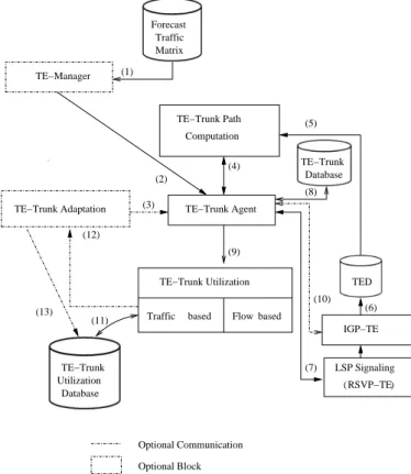
In this section we propose a generic architecture to describe an MPLS-TE Routing System (Fig. 1). This is a functional architecture that helps in covering a large solution spec-trum. It is comprised of a set of functions also called build-ing blocks. Some of these buildbuild-ing blocks are runnbuild-ing on routers, others may be running either on routers or on one or more network servers. We distinguish standard MPLS-TE blocks and implementation specific blocks:
• Standard MPLS-TE functions include the TE
Topol-ogy Discovery function ensured by an IGP-TE proto-col (either OSPF-TE or ISIS-TE) and the LSP
Sig-TE−Trunk TE−Manager IGP−TE TED RSVP−TE ( Optional Communication Optional Block TE−Trunk Path Computation Forecast Traffic (3) (5) (6) (7) (2) (1) (4) (8) (9) (12) (11) (13) TE−Trunk Database LSP Signaling Matrix ) (10)
TE−Trunk Adaptation TE−Trunk Agent
Database Utilization
TE−Trunk Utilization based Flow based Traffic
Figure 1. Generic architecture for MPLS-TE Routing Sys-tems
nalling function ensured by the RSVP-TE protocol. These standard functions are located in routers.
• Implementation specific functions include the
TE-Trunk Agent, the TE-TE-Trunk Path Computation, the TE-Trunk Adaptation and the TE-Trunk Utilization functions. These functions may be located in routers or externalized in one or more network servers. This also comprises the TE-Manager function which is al-ways located on a network server.
In the below sections we focus on the five building blocks in charge of resource optimization: Manager (TM), Trunk AGent (TAG), Trunk Computation (TC), TE-Trunk ADaptation (TAD), and TE-TE-Trunk Utilization (TU).
3.1 TE-Manager
The TE-Manager (TM) is a functional entity that takes the decision to setup/release/modify TE-Trunks by relying on the forecast traffic matrix (1), that is the set of aggregate traffic demands between each pair of Edge Routers. It sends TE-Trunk setup/deletion/modification requests to the set of one or more TE-Trunk Agents (2). This function is optional, TE-Trunks may be defined by the operator and may be directly configured on TE-Trunk Agents.
3.2 TE-Trunk Agent
The TE-Trunk Agent (TAG) is the heart of the
architecture. It controls the TE-Trunks
establish-ments/modifications/deletions in the network. It coordi-nates the actions of the TE-Manager, the TE-Trunk Adap-tation, the TE-Trunk Path compuAdap-tation, the TE-Trunk Uti-lization and the LSP Signalling blocks. It handles Trunk setup/deletion/modification requests sent by the TE-Manager (1), and TE-Trunk modification requests sent by the TE-Trunk Adaptation block (3). It sends TE-Trunk Computation requests to the TE-Trunk Path Computation block (4). Once paths are computed the TE-Trunk manager sends LSP setup requests to the RSVP-TE module (7) so as to signal the TE-LSPs along the computed paths. Once the LSPs are setup, the Trunk Agent feeds the TE-Trunks Database which contains information related to the established TE-Trunks (TE-Trunk constraints, TE Trunk paths, etc.) (8). It also communicates the established TE-Trunks and the corresponding LSPs to the TE-Trunk Uti-lization block (9). In an ”Online mode”, it may communi-cate with the IGP-TE (10) and LSP Signalling blocks so as to be notified of network (link/node) and TE-LSPs failures. This communication allows the TE-Trunk Agent to detect failures and call the TE-Trunk Path Computation block so as to reroute the TE-Trunks on paths avoiding failed ele-ments.
3.3 TE-Trunk Path Computation
The TE-Trunk Computation block (TC) is a fundamental building block in MPLS-TE Routing Systems. It has to find TE-Trunks paths by operating on the Traffic Engineering Database (TED) (5) fed up by the IGP (6) and considering the TE-Trunks constraints. It handles Trunk Computation requests sent by the TE-Trunk Agent. A request may cor-respond to a single TE-Trunk or to a set of TE-Trunks. The request may be a Trunk setup request or a Trunk modifi-cation one. The output for a given Trunk is a path or a set of paths whose cumulative bandwidth fits the Trunk(s) request.
3.4 TE-Trunk Adaptation
The TE-Trunk Adaptation block (TAD) is in charge of adapting TE-Trunk size to the actual traffic load. It in-creases TE Trunk size (i.e. it inin-creases the amount of band-width reserved for the TE-Trunk), so as to anticipate con-gestion issues, when the load between a pair of nodes in-creases, and decreases TE Trunk size so as not to waste unused bandwidth when the load between a pair of nodes decreases. Verification of the TE-Trunk load can be done in a timer driven manner, in which case the TE-Trunk load in the TE-Trunk Utilization databases is periodically checked by the Adaptation block (13) or it can also be done in an
event driven manner, in which case the TE-Trunk
Utiliza-tion block notifies the AdaptaUtiliza-tion block that a TE-Trunk is
congested or is going to be congested (12). Note that this block is optional and may not be used in every MPLS-TE Routing Systems.
3.5 TE-Trunk Utilization
The TE-Trunk Utilization block (TU) is in charge of (1)-Mapping of traffic within TE-Trunks, (2)- mapping of in-coming flows within TE-LSPs (LSP selection among the set of LSPs of a given Trunk), (3) traffic policing within Trunks (rate limiting), (4)- checking the actual TE-Trunk load, and optionally (5)- performing flow admission control within Trunks. Mapping of traffic within TE-Trunks, on the head-end router may rely on the IGP (e.g. the trunk is considered as a link in the SPF computation), on BGP (e.g. all prefixes reachable via the trunk tail-end are routed within the trunk) or finally on static routes within the trunk. Mapping of a particular flow within an LSP of a given TE Trunk, can be done either in advance, when flow admission control is done, or in real time by relying on a hash function that respects flows. Traffic policing, that is, rate limiting on Trunk Edge Routers can be done on a
per-flow basis or on an aggregated traffic basis. The control
of the TE-Trunk load consists in updating the TE-Trunk Utilization Database with the actual TE-Trunk load. This database includes the current load of LSPs. Updating the TE-Trunk Utilization database with the actual traffic load within LSPs, may be achieved by measurement on the Edge Routers or by cumulating the requested bandwidth of each admitted flow, when flow admission control is performed. This information can then be used by the TE-Trunk Adap-tation block so as to anticipate congestion within a Trunk and ensure adaptation to traffic matrix changes. It can also be used for flow admission control. In a flow aware mode, the TE-Trunk Utilization block can handle flow ad-mission requests. Upon reception of a flow adad-mission re-quest, it consults the TE-Trunk Utilization database (11), and if there is an LSP with sufficient resources, the new flow is accepted and the TE-Trunk Utilization database is updated. Else, the flow admission request is rejected. Al-ternatively when there is no TE-Trunk with enough avail-able bandwidth, the TE-Trunk Utilization block may ask the TE-Trunk Adaptation block to increase a TE-Trunk size in order to provide enough capacity for the new flow (12).
4 Applying the architecture: Functions
dis-tribution and implementation options
In the previous section we proposed a functional archi-tecture for MPLS-TE systems, which includes in addition to standard MPLS-TE blocks, specific blocks such as TE-Trunk Computation, TE-TE-Trunk Adaptation and TE-TE-Trunk Utilization. This architecture may help classifying MPLS-TE mechanisms and improve the design of MPLS-MPLS-TE sys-tems. An MPLS-TE routing system corresponds actually to a specific implementation of this architecture. The blocks
of this generic architecture may be located in different el-ements (Centralized on Network servers or distributed in Edge routers). The performances of an MPLS-TE routing system, in terms of scalability, reactivity and optimality ac-tually depend on various implementation options, includ-ing the repartition of the functions. Before discussinclud-ing these options, a description of some classification criteria which will help the discussion, is proposed.
4.1 MPLS-TE classification criteria
Several criteria are identified to arrange the various ap-proaches for implementing an MPLS-TE Routing Systems. We distinguish the following:
1. Time Scale:
• Offline (Of f ): TE-Trunks are computed and
es-tablished periodically based on forecast traffic matrices. This mode allows more time for path computation. This implies that there is no TE-Trunk Adaptation and no LSP re-routing upon network failures. In this mode, recovery can be ensured by pre-computing backup TE-Trunks.
• Online (On): TE-Trunks are modified
(TE-Trunks resizing, LSPs re-routing, LSPs cre-ation/deletion) according to traffic matrix evo-lution, or network failure. In such mode, path computation time should be minimized so a to ensure good reactivity.
2. Path Computation Method:
• Coordinated (Coo): TE-Trunk paths are
com-puted taking into account all TE-Trunks re-quests.
• Uncoordinated (U nc): The path(s) of TE-Trunks
starting on a given Edge Router are computed without taking into account TE-Trunks origi-nated by other head-end LSRs.
3. Function Distribution:
• Centralized (Cen): The function is located on a
single computing element
• Distributed (Dis): The function is distributed on
multiple computing elements. 4.2 Function Distribution
We discuss in this section the distribution of each architec-ture’s function and its impact on the performances of an MPLS-TE System. Some functions should be only Dis-tributed, others only Centralized and others can be either Distributed or Centralized. When two functions are not lo-cated within the same element (e.g. One is lolo-cated on an Edge Router and the other is located on a TE server) a com-munication protocol is required to manage the relationships
and cooperations between the two functions. In contrast, when two functions are located on the same element (e.g. Edge Router) there is no need for any communication pro-tocol, and their relationship may simply rely on a software interface (e.g. an API).
• The MPLS-TE protocols (RSVP-TE and IGP-TE) are
Distributed on the routers (note that the IGP-TE may passively run on the Path Computation Block when it is Centralized, so as to feed the TED).
• The TE-Trunk Utilization block should be Distributed
as it is in charge of the routing of incoming flows within the TE-Trunks and of TE-Trunk load measure-ment on Edge Routers. The centralization of this block may affect the reactivity of the MPLS-TE Sys-tem due to the amount of information to be communi-cated between Edge Routers and the TE-server.
• By definition, the TE-manager is always Centralized. • The TE-Trunk Agent can either be Centralized on a
network server or Distributed on Edge Routers. In a Distributed mode, it maintains only TE-Trunks for which it is the head-end. In a Centralized scenario, the TE-Trunk Agent has a global knowledge of all the TE-Trunks, and a communication protocol is re-quired to communicate with Edge Routers (with the LSP signalling process) so as to trigger LSP setup and retrieve failure events. This may rely for instance on a standard management protocol (e.g. SNMP [12]). Note that in the Centralized mode, the notification of network failure events should be event-driven (e.g. SNMP traps) so as to minimize the amount of in-formation to be communicated between the Edges Routers and the TE-server.
• The TE-Trunk Adaptation function should always be
linked to the TE-Trunk Agent, that is if the TE-Trunk Agent is Centralized (respectively Distributed), the TE-Trunk Adaptation is also Centralized (respectively Distributed). When the TE-Trunk Adaptation is Cen-tralized, a communication protocol is required be-tween the TE-Trunk Utilization block located on Edge Routers and the TE-Trunk Adaptation, so as to re-trieve the LSP load. Such dynamic discovery of LSP load should be event-driven so as to minimize the amount of information communicated between Edge Routers and the TE-server (The TE-Trunk Utilization block sends a message to the Adaptation block only whenever a threshold is reached and this avoids the Adaptation block to periodically consult the TE-Trunk Utilization database). The separation of these two functions (the TE-Trunk Adaptation and the TE-Trunk Agent) would not bring any value and would require communicating a lot of information.
• The TE-Trunk Path Computation block may be
Agent is Centralized, the TE-Trunk Path Computation block should also be Centralized (Coordinated mode) because the separation of these two functions would not bring any value and would require the communi-cation of a lot of information. (2) But, if the TE-Trunk Agent is Distributed, the TE-Trunk Path Computation block may either be Distributed or Centralized. When the TE-Trunk Agent is distributed and the TE-Trunk path Computation is Centralized, the TE-Trunk Path Computation remains Uncoordinated because the set of TE-Trunk Agents send requests independent from each other.
4.3 Various implementation options
There are several approaches for MPLS-TE Routing Systems, which correspond actually to several combi-nations of the criteria listed above. We discuss below some of these approaches which correspond to particular implementations of our architecture.
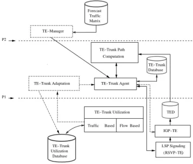
4.3.1 The Off/Cen/Coo MPLS-TE approach
We consider here an Offline mode based approach, where the TE-Trunks paths, potentially including backup paths, are pre-computed periodically without real time compu-tation constraints, in a Coordinated manner. The Fig. 2 shows the distribution of MPLS-TE functions in such ap-proach. The cursor in position P1, separates the blocks which are Centralized on a TE-server (above the cursor) from those which are Distributed on Edge Routers (under the cursor). There is no TE-Trunk adaptation as we are in an Offline mode. The Trunk Path Computation, the TE-Trunk Agent and the TE-TE-Trunk Adaptation blocks are Cen-tralized (actually the TED is maintained on router). Other blocks: TE-Trunk Utilization, IGP-TE, RSVP-TE are lo-cated on Edge Routers (actually IGP-TE and RSVP-TE are located on all routers). In this approach, the placement of Trunks can be drastically optimized because the TE-Trunk Path Computation function knows all the requests and can perform a Coordinated path computation, with no time limitation. In return, by definition this Offline ap-proach does not allow reacting upon traffic matrix change or network failure and this may lead to packet loss upon congestion or service disruption upon failure. Also even if this approach allows the pre-establishment of backup paths, such protection may not work upon a multiple failure cases and hence faces some robustness limitations. Thus, the Off/Cen/Coo approach obviously suffers from a lack of sur-vivability and reactivity as it does not allow adaptation to traffic variations and topology changes.
4.3.2 The On/Cen/Coo MPLS-TE approach
If we add a TE-Trunk Adaptation block and a TE-Trunk re-routing capability to the previous system, it ends up with
TE−Trunk TE−Manager P1 P2 IGP−TE TED RSVP−TE ( ) Forecast Traffic TE−Trunk Database Matrix Database LSP Signaling Utilization TE−Trunk Agent TE−Trunk Adaptation Computation TE−Trunk Path TE−Trunk Utilization Flow Based Based Traffic Centralized−Distributed Demarcation
Figure 2. The Off/Cen/Coo and On/Dis/Unc MPLS-TE mechanisms
an Online mode and this results in an On/Cen/Coo MPLS-TE System. Such approach can operate but it may require a lot of information exchanges between Edge Routers and the TE-server and suffers from a limited reactivity. Indeed, the recovery upon a network failure implies the following sequences: (1) Failure discovery on the TE-server, (2) Co-ordinated path computation and (3) Communication of the new paths to all Edge Routers. Such sequence may take long time, particularly when a lot of Trunks are impacted.
4.3.3 The On/Dis/Unc MPLS-TE approach
In this Online approach, the MPLS-TE Routing System contains an adaptation function. The requests are han-dled in an Uncoordinated manner. The TE-Manager re-mains Centralized, however all other architecture’s blocks are Distributed on the Edge Routers, which corresponds to the position P2 for the centralized/distributed cursor in the Fig. 2. This approach offers better reactivity and recovery time than the On/Cen/Coo approach thanks to its On/Dis scheme. In fact, in addition to the reactivity offered by the online mode, all functions of a given MPLS-TE System are located on the same element (the Edge Router) and hence this does not require heavy communication between Edge Router and the TE-server. In return, it affects the optimality because of the Uncoordinated scheme. The higher the level of reactivity and robustness is, the more affected the opti-mality is. Note that here the optiopti-mality may be affected by the order in which the TE-Trunk/LSP paths are computed. If instead of adopting an Uncoordinated scenario, the Coor-dinated mode was used, this would result in an On/Dis/Coo MPLS-TE System.
4.3.4 The On/Dis/Coo MPLS-TE approach
This approach implies that each Edge Router has to be aware of all the TE-Trunk requests and operate in a Co-ordinated manner with other network Edge Routers. This improves the usage of the network resources, but remains less advantageous compared to the Offline mode, due to its limited scalability. In fact, the edge routers can be sat-urated, since each one has to exchange all the information about its own TE-Trunks/LSPs with all other Edge Routers. This cannot scale because of the number of TE-Trunks in the network and their activity (resizing rates and so on). So, this approach seems not relevant.
The analysis carried above shows that each approach has its own advantages and drawbacks. Let’s discuss in the fol-lowing section an other approach that brings together con-flicting modes to take advantages of each of theme.
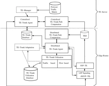
4.3.5 The hybrid MPLS-TE approach
This approach is based on a hybrid scheme: On/Dis/Unc-Off/Cen/Coo approach. In this case, a TE-Trunk layout is computed and setup periodically (e.g. weekly) in an Offline mode. Between periods, the Online mode is used and traf-fic matrices and topology changes are handled dynamically. This mechanism maintains two TE-Trunk Agents: A Cen-tralized TE-Trunk Agent without adaptation function and a Distributed TE-Trunk Agent with an Adaptation function. It maintains also two Path Computation blocks linked to the both TE-Trunk Agents: A Centralized and a Distrib-uted one (Fig. 3). Others blocks are located only in Edge Routers.
Such combination of two MPLS-TE approaches seems re-ally relevant as it takes advantage of the optimality offered by the Offline, Centralized and Coordinated modes and the reactivity, robustness, scalability and survivability assured by the Online, Distributed and Uncoordinated modes. In return, this approach raises issues in terms of cooperation between the different modes. This approach can be applied to a protected MPLS-TE layout where primary TE-Trunks are protected by local fast reroute backup TE-Trunks. Pri-mary TE-Trunks are established in an Online manner to en-sure as much adaptability and reactivity as possible, while Backup TE-Trunks are established in an Offline manner, without real time computation constraints ,so that their path can be optimized as much as possible, in order to avoid backup resources starvation.
The key challenge raised by this hybrid scheme re-lies on how to manage the handover between Offline and Online operations. A difficulty can arise when, in the Of-fline mode, the resource reservation for TE-LSPs is not ex-plicitly done. When the reservation is not done, the On-line mode ignores the resources taken by the OffOn-line mode. A solution can consist in using two bandwidth pools on the same link to separate Online resources from Offline resources. These pools must be dynamically adjusted to avoid blocking the resources of a pool while the other pool
TE−Trunk IGP−TE RSVP−TE ( LSP Signaling ) Database Utilization
based Flow based Traffic TE−Manager Traffic Forecast Matrix TE−Trunk Agent Centralized TE−Trunk Agent Computation TE−Trunk Path Distributed Computation TE−Trunk Path Centralized Database TE−Trunk TE−Trunk Adaptation TED
TE−Trunk Utilization Edge Router TE−Server
Distributed
Figure 3. Hybrid MPLS-TE Approach
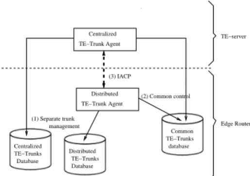
is under-utilized. Path computation has to take the band-width pool type into consideration. Another problem deals with the morphing of TE-Trunks between an Online and an Offline sequence (e.g. The migration from the Online mode to the Offline one). It consists, in this case, in con-trolling the transfer of a TE-Trunk management between a Distributed TE-Trunk Agent and a Centralized TE-Trunk Agent. Two scenarios for TE-Trunk management can be distinguished (Fig. 4): (1) Separate the management of the TE-Trunks which are created in Centralized mode (Offline TE-Trunks) from those which are established in Distrib-uted mode (Online TE-Trunks). This approach allows each Agent to manage separately its TE-Trunks. It implies two distinct types of TE-Trunks (Offline TE-Trunks and On-line TE-Trunks). (2) Centralized and Distributed control of the same TE-Trunk. In this approach, the management of a given TE-Trunk is shared between the Centralized and the Distributed TE-Trunk Agents. This requires more care in the cooperation between the two TE-Trunks Agents. In both scenarios, an Inter-Agent Communication Protocol (IACP) (3) would be useful, so as to synchronize the two Agents and coordinate the migration between the Offline and online modes. In case of separate TE-Trunk manage-ment the IACP protocol would have to carry information related to the creation, suppression and evolution of Online TE-Trunks, from the Distributed Agent to the Centralized Agent. It would also have to carry notification of an Offline re-optimization, from the Centralized Agent to the Distrib-uted Agent. In case of common TE-Trunk management, the IACP protocol would have to carry information allow-ing a transfer of TE-Trunk ownership between Centralized and Distributed Agents. For instance this could rely on a master-slave scheme, where the Centralized Agent is the master and notifies the Distributed Agent when it needs to take control of the TE-Trunks, i.e. when an Offline opti-mization is triggered.
Centralized TE−Trunks database TE−Trunks Database Database (3) IACP Centralized (1) Separate trunk management TE−server Edge Router TE−Trunks TE−Trunk Agent TE−Trunk Agent Distributed Distributed Common (2) Common control
Figure 4. TE-Trunks management
5 Conclusion
MPLS-TE is being deployed by network operators to bet-ter optimize their network resources. Routing in MPLS-TE networks is a large and open issue. Studies aimed to improve the MPLS-TE Routing in terms of scalability, sta-bility, robustness, optimality and survivability. In this pa-per, we have proposed a generic architecture for MPLS-TE Routing Systems, that combines a set of MPLS-MPLS-TE building blocks such as TE-Trunk Computation, TE-Trunk Utilization and TE-Trunk Adaptation. The goals of this generic architecture are to ease the classification of exist-ing MPLS-TE Routexist-ing solutions, and to help in improvexist-ing existing solutions or designing new solutions.
We have illustrated the interest of such architecture with a qualitative evaluation of various MPLS-TE implemen-tation approaches and we have identified the need for an Inter-Agent Communication Protocol (IACP) to facilitate the synchronization between Online and Offline control functions in a hybrid MPLS-TE approach.
Further works will focus on an evaluation of the discussed implementation options with regards to a set of evaluation metrics: optimality, scalability, reactivity, stability and ro-bustness. Also, a functional specification of the IACP pro-tocol will be performed.
Acknowledgement
The authors would like to thank R. Moignard, P. Chemouil, B. Jabbari and Y. Le Louedec for their helpful comments and suggestions.
References
[1] D. Awduche and B. Jabbari, “Internet traffic engineer-ing usengineer-ing multi-protocol label switchengineer-ing (MPLS),”
Computer Networks, vol. 40, no. 1, pp. 111–129,
Sep-tember 2002.
[2] H. Smit and T. Li, “IS-IS extensions for traffic engi-neering,” RFC 3784, June 2004.
[3] D. Katz, K. Kompella, and D. Yeung, “Traffic en-gineering (TE) extensions to OSPF version 2,” RFC 3630, September 2003.
[4] D. Awduche, L. Berger, D. Gan, T. Li, V. Srinivasan, and G. Swallow, “RSVP-TE: Extensions to RSVP for LSP tunnels,” RFC 3209, December 2001.
[5] T. L. M. Kodialam, “Minimum interference routing with applications to MPLS traffic engineering,” in
IN-FOCOM, 2000.
[6] W. Szeto, R. Boutaba, and Y. Iraqi, “Dynamic online routing algorithm for MPLS traffic engineering,” The
International Journal of Network and Systems Man-agement, vol. 10, no. 3, pp. 936–946, 2002.
[7] P. W. S. Suri, M. Waldvogel, “Profile-based routing: A new framework for mpls traffic engineering,”
Qual-ity of future Internet Services, no. 2156, pp. 138–157,
2001.
[8] A. Elwalid, C. Jin, S. H. Low, and I. Widjaja, “MATE : MPLS adaptive traffic engineering,” in INFOCOM, 2001.
[9] K.-T. K. S. Phuvoravan, “Fast time scale control for MPLS traffic engineering,” CS-TR 4351, April 2002. [10] A. Bosco, “Edge distributed admission control in
MPLS networks,” IEEE Communications Letters, vol. 7, no. 2, pp. 88–90, Febrary 2003.
[11] D. Awduche, J. Malcolm, J. Agogbua, M. O’Dell, and J. McManus, “Requirements for traffic engineering over MPLS,” RFC 2702, September 1999.
[12] J. Case, M. Fedor, M. Schoffstall, and J. Davin, “A simple network management protocol (SNMP),” RFC 1098, May 1990.