HAL Id: hal-01568437
https://hal.sorbonne-universite.fr/hal-01568437
Submitted on 25 Jul 2017
HAL is a multi-disciplinary open access
archive for the deposit and dissemination of
sci-entific research documents, whether they are
pub-lished or not. The documents may come from
teaching and research institutions in France or
abroad, or from public or private research centers.
L’archive ouverte pluridisciplinaire HAL, est
destinée au dépôt et à la diffusion de documents
scientifiques de niveau recherche, publiés ou non,
émanant des établissements d’enseignement et de
recherche français ou étrangers, des laboratoires
publics ou privés.
System-Level Design for Communication-Centric Task
Farm Applications
Daniela Genius, Ludovic Apvrille
To cite this version:
Daniela Genius, Ludovic Apvrille. System-Level Design for Communication-Centric Task Farm
Appli-cations. 12th International Symposium on Reconfigurable Communication-centric Systems-on-Chip ,
Jul 2017, Madrid, Spain. �hal-01568437�
System-Level Design for
Communication-Centric Task Farm
Applications
Daniela Genius
Sorbonne Universités, UPMC Paris 06, LIP6, CNRS UMR 7606, [email protected]
Ludovic Apvrille
LTCI, CNRS, Telecom ParisTech, Université Paris-Saclay, IMT, [email protected]
Abstract—Massively parallel applications such as telecommunication and video streaming have the par-ticularity that a large proportion of the time is spent on accessing communication channels between the tasks, due to contention on the on-chip interconnect. Moreover, the analysis of a given task deployment is often fastidious. Thus, we propose to extend an ex-isting easy-to-use System-level Design methodology to task farm applications. The contribution first concerns adding relevant SysML modeling elements to take into account application code, hardware platforms and deployment constraints. Secondly, new modeling elements – including access techniques to communica-tion channels – must be given a semantics in order to transform models into a well-defined SystemC virtual prototyping MPSoC platform. A telecommunication application serves as an example.
I. INTRODUCTION
It has become a common practice to model critical software components with model-driven approaches, one reason being to facilitate their execution analysis with simulation techniques.
Multiprocessor-on-chip system (MPSoC)
architec-tures feature complex, sometimes hierarchical, interconnect-on-chip architectures, allowing to ex-ecute communication-centric applications such as telecommunication and video streaming. Yet, usual UML/SysML-based model-driven approaches do not natively support such task-farm applications, both in terms of structure and behavior description. Nor do they offer efficient and easy ways to ana-lyze critical aspects of MPSoC supporting such as contention in the communication infrastructure.
In a previous contribution targetting the genera-tion of virtual prototypes for this particular class of applications [13], design and mapping were purely text-based, thus limiting its usage mostly to aca-demic research, and not to engineers more willing to use graphical frameworks. Hardware components had to be either described by hand, which is error-prone, or generated from a Python specification, and thus be practically unreadable and hard to debug or refactor.
This paper proposes an integrated method and a tool to model critical task-farm software compo-nents and to evaluate their deployment on massively parallel candidate MPSoCs. Models are performed with a UML/SysML editor. Model transformations techniques are used to convert the application and the hardware architecture into a SystemC-based virtual prototyping platform. The latter can easily be executed, and performance metrics can be obtained with scripts. Last but not least, tasks and channel models have been given a formal semantics in timed automata, thus allowing to use formal verification on the application before it is deployed. [5].
The paper is organized as follows. Section II presents the related work. Section III gives an overview of our previous contributions to virtual prototyping, while Section IV explains how we use the semantics of AVATAR channels to express the task farm property. Section V illustrates our approach by means of a case study. Section VI concludes the paper.
II. RELATEDWORK
During the software development process, soft-ware components are generally tested/executed on a local host, and only later integrated once the target is available. Software-hardware integration is postponed to the availability of the hardware target. Thus, the inadequacy of software/hardware interac-tions that cannot be found with local code execution may induce late and costly software revising.
A more adequate approach is to frequently val-idate the different refinements of software compo-nents in a as-realistic-as-possible hardware environ-ment. FPGAs can be used for this purpose [15], but the hardware environment is still required to be developed in a detailed way and then flashed onto a sometimes costly FPGA.
A promising solution is the use of virtual pro-totyping platforms. Their obvious drawback is that software execution is commonly less realistic, and takes much longer with regards to FPGAs or real targets. But they offer more flexibility, and they are probably more convenient for software engi-neers with little knowledge about hardware plat-forms. Many fully software-based prototyping en-vironments have been proposed. Some of them are restricted to high-level analysis and offer only func-tional simulation, while others offer extended profil-ing capabilities. PtolemyII [8] proposes a modelprofil-ing environment for the integration of diverse execution models, in particular hardware and software compo-nents. If design space exploration can be performed, its first intent is the simulation of the modeled systems.
In Polis [17], applications are described as a network of state machines. Each element of the network can be mapped on a hardware or a software node. This approach is more oriented towards appli-cation modeling, even if hardware components are closely associated to the mapping process. Metropo-lis [2] is an extension of PoMetropo-lis. It targets heteroge-neous systems and offers various execution models. Architectural and application constraints are closely interwoven. Sesame [9] proposes modeling and simulation of features at several abstraction levels. Preexisting virtual components are combined to form a complex hardware architecture. In contrast to
Metropolis, application and architecture are clearly separated in the modeling process. Models’ seman-tics vary according to the levels of abstraction, ranging from Kahn process networks (KPN [16]) to data flow for model refinement, and to discrete events for simulation purpose. Currently, Sesame is limited to the allocation of processing resources to application processes. It neither models memory mapping nor the choice of the communication ar-chitecture. The ARTEMIS [19] project originates from heterogeneous platforms in the context of research on multimedia applications in particular; it is strongly based on the Y-chart approach. Ap-plication and architecture are clearly separated: the application produces an event trace at simulation time, read in by the architecture model. However, behavior depending on timers and interrupts cannot be taken into account.
MARTE [21] shares many commonalities with our approach, in terms of the capacity to separately model communications from the pair application-architecture. However, it intrinsically lacks sepa-ration between control aspects and message ex-changes. Other works based on UML/MARTE, such as Gaspard2 [11], are dedicated to both hardware and software synthesis, relying on a refinement process based on user interaction to progressively lower the level of abstraction of input models. Still, such a refinement does not completely separate the application (software synthesis) or architecture (hardware synthesis) models from communication. Di Natale et al. [7] propose the generation of communication managers for software low layers. Yet, they do not handle the specificity of task-farm applications nor they offer formal verification.
AVATAR [18] is a SysML-based environment for modeling the software components of complex embedded systems. It proposes operators describe temporal constraints; formal simulations and veri-fication can be performed from the models. Gen-erated code can be used with a SystemC based simulation engine to perform a cycle-accurate sim-ulation [14]. However, it does not offer support for communication-centric task-farm type applications. Typical applications include automotive, avionics, but also smaller embedded applications. They have
in common that they are control-oriented, but they do not handle communication-bound, and high throughput, systems.
MDGen from Sodius [20] starts from Rhapsody, which can automatically generate software, but not hardware descriptions from SysML. SysML in Rhapsody is untimed and sequential. Timing and hardware specific artifacts such as clock/reset lines are generated automatically.
Batori [3] proposes a design methodology for telecommunication applications. From use cases, the method proposes several formalisms to capture the application structure ("interaction model") and behavior (Finite State Machine) and for its deploy-ment from which executable code can be generated. The platform seems limited to specific components and no design exploration seems possible; code gen-eration targets a real platform, and not a prototyping environment.
In summary, most of these environments do not handle explicitly task-farm applications. On the contrary, the contribution presented in this paper explicitly addresses these applications both in terms of modeling, simulation and formal verification aspects.
III. VIRTUALPROTOTYPING
SoCLib[1] is a public domain library of
compo-nent models written in SystemC targeting shared-memory MPSoC architectures based on the
Vir-tual Component Interconnect (VCI) protocol [22],
which clearly separates the components’ functional-ity from communication. Hardware components are either initiators (typically a CPU with its caches), targets (typically RAM), or sometimes both (DMA, configurable hardware accelerators and I/O copro-cessors).
A tool chain for generating code to be executed in MPSoCs has been defined and implemented [12]. Its objective is to transform SysML application diagrams , hardware architecture diagrams and map-ping diagrams into a SoCLib representation. So-called deployment diagrams are used to capture allocations of software components onto a MPSoc platform. From the diagrams, a code generator translates each SysML software block into a POSIX
thread, and a ldscript generator generates the linker script taking into account the mapping specified in the deployment diagram. Finally, The top cell
generator generates a SystemC top cell for
cycle-accurate bit-cycle-accurate simulation.
However, this contribution was lacking a a formal semantics. This paper thus proposes to provide a complete semantics for these applications, in the scope of the prototyping and the design space exploration of these applications.
IV. EXTENDING THESEMANTICS OF
COMMUNICATIONCHANNELS
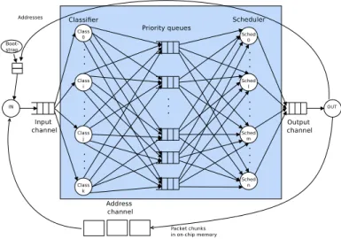
This section explains how we propose to extend models/diagrams and code generation capabilities to support task-farm applications. In the field of embedded systems, communications are typically one-to one, more rarely one-to-many e.g. broadcast communication. Task farm applications are typi-cally multimedia streaming and high-performance packet processing e.g. in routers, see Figure 1. Contrary to general embedded applications, the communication in task-farm application generally rely on multi-writer multi-reader communication channels where any number of reader or writer tasks can access these channels. Said differently, a task waiting for some data to be processed indifferently picks up data from common buffers, thus introduc-ing a high degree of non-determinism difficult to capture in a pure FIFO model (e.g., Kahn models). It is a common practice to transform UM-L/SysML models to Timed Automata specifications, as explained in [18]. Based on this idea, we decided to enhance the AVATAR methodology of [18] to describe the software part of our application: the structure of the application is described with SysML block diagrams, and the behavior of each task is described with state machine diagrams. A software model, i.e. its structure and its behavior, can be transformed into a set of communicating timed automata.
An example of non-deterministic behavior is shown on the left side of Figure 2 where two SysML blocks communicate via a channel. Multi-writer multi-reader channels are intrinsically asyn-chronous, and thus part of their semantics can be
Fig. 1. Classification application task and communication graph <<block>> B0 ~ out m0() ~ out m1() <<block>> B1 ~ in m0() ~ in m1() m0() state0 m1() Waiting4Sig m1() m0() after (2,12) after (5,15) after (10,20)
Fig. 2. Non-deterministic semantics
related to the semantics of AVATAR asynchronous channels. Avatar asynchronous channels are de-picted with origin and termination ports filled in white. The right part of Figure 2 shows the state ma-chine diagrams of blocks B0 and B1, respectively. A non deterministic system is modeled. Indeed, B0 can decide to send either m0 or m1. B1 waits for one of the two message, or after a given time without receiving one of the two ("after(10,20)"), it resets the waiting time of messages by taking the central transition from its main state.
V. CASESTUDY
The task and communication graph in Figure 1 features a massively parallel telecommunication application (i.e., a task farm application), where all
tasks of a stage n can read the data output by all tasks of stage n − 1. In this particular application, network packets are first cut into chunks of equal size by the input co-processor. Each packet chunk has a descriptor referencing the address of the next chunk. Overall, a chunk contains a 32-bit address, 11 bits to describe its TotalSize, 20 bits date for a time stamp, and a Boolean internal indicating if the packet is stored on-chip of off-chip, for a total of 64 bit (8 byte). Only these descriptors are sent through the channels: the packet chunks themselves are stored in on-chip or off-chip memory.
Tasks of the application are the following. A bootstrap taskorganizes the system start-up and fills the address channel with addresses generated from
the memory segment(s) where packet chunks are to be stored. The input task accepts addresses from a channel. It reads Ethernet encapsulated IP packets, cuts them into slots of equal size, and copies these slots to dedicated memory regions. A classification
task reads one or several descriptors at a time and
then retrieves the first chunk of the corresponding packet from memory (not shown in the Figure to preserve readability; any classification task can access to any chunk). The scheduling task reads the priority queues, then writes the descriptor to the output queue. Both classification and scheduling tasks use try-read primitives to get work whenever it is available and thus maximize performance. The
output taskconstantly reads the output queue. Each
time a slot is read, its liberated addresses are sent to the address channel for reuse.
A. Modeling
To model this application in AVATAR, we con-sider only the software tasks, thus ignoring the input and output coprocessors and the bootstrap task. The central part of Figure 1 displays what is contained in the AVATAR model.
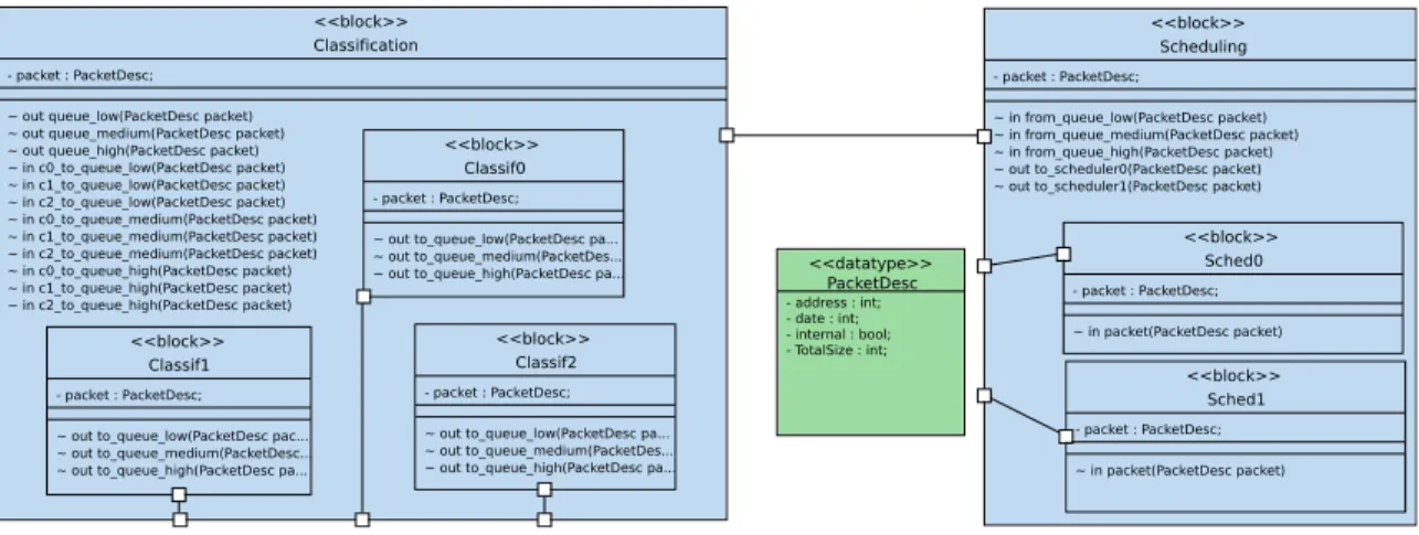
Figure 3 shows the block diagram of the Telecommunication Application. The packet
de-scriptor is modeled as a data type 1 The central
channel, visible as a unique main channel in the SysML block diagram, contains in fact the three priority queues, modeled as AVATAR signals. Each priority queue (high, medium, low) is translated into a separate multi-writer multi-reader channel for the SoCLib platform.
Figure 4 shows on the left the state machine diagram of the classifier. It models the sending of a packet descriptor from the classifier to the priority queues. Depending on the priority, the packet is sent to queue high, medium, or low. To ensure non-determinism on the handling of data, several classification tasks are instantiated2, and the Waiting
state of classification tasks has several non deter-ministic transitions, i.e. a random data is selected
1Currently, only int and Boolean data types are made explicit
in the model, bit wise modeling is not yet possible.
2Three tasks are shown for space restrictions, but there can
be any number of classification tasks, independently from the number of channels and from the number of packet priorities
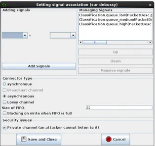
Fig. 5. Channel configuration window
among the possible channels having at least one data available. once a classification task has read a data, it proceeds i to one of the states Low, Medium, or High depending on the priority determined by the classification tasks. Finally, packets of the same priority are sent to the appropriate queue.
On the right we show the reception of packets stemming from any of the three priority queues by the scheduler task. Again, packets are read indiffer-ently from all three queues and then dispatched in the Dispatch state to any of the available scheduler task (two scheduling tasks are instantiated in the example).
The channel type of the priority queues is lossy, an option available in AVATAR. This is necessary to model the fact that incoming packets can be thrown away if the channel is full. Figure 5 shows the configuration dialog window of a channel: the upper part of the window is dedicated to the interconnec-tion of ports, with connected ports on the right, and non connected ports on the left. Options of channels are listed in the central part of the figure: synchronous, asynchronous, channel depth (here: 32 items), blocking or non blocking, broadcast, lossy and privacy.
<<block>> Scheduling - packet : PacketDesc; ~ in from_queue_low(PacketDesc packet) ~ in from_queue_medium(PacketDesc packet) ~ in from_queue_high(PacketDesc packet) ~ out to_scheduler0(PacketDesc packet) ~ out to_scheduler1(PacketDesc packet)
<<block>> Sched0 - packet : PacketDesc; ~ in packet(PacketDesc packet) <<block>> Sched1 - packet : PacketDesc; ~ in packet(PacketDesc packet) <<block>> Classification - packet : PacketDesc; ~ out queue_low(PacketDesc packet) ~ out queue_medium(PacketDesc packet) ~ out queue_high(PacketDesc packet) ~ in c0_to_queue_low(PacketDesc packet) ~ in c1_to_queue_low(PacketDesc packet) ~ in c2_to_queue_low(PacketDesc packet) ~ in c0_to_queue_medium(PacketDesc packet) ~ in c1_to_queue_medium(PacketDesc packet) ~ in c2_to_queue_medium(PacketDesc packet) ~ in c0_to_queue_high(PacketDesc packet) ~ in c1_to_queue_high(PacketDesc packet) ~ in c2_to_queue_high(PacketDesc packet) <<block>> Classif2 - packet : PacketDesc; ~ out to_queue_low(PacketDesc pa... ~ out to_queue_medium(PacketDes... ~ out to_queue_high(PacketDesc pa...
<<block>> Classif1
- packet : PacketDesc; ~ out to_queue_low(PacketDesc pac... ~ out to_queue_medium(PacketDesc... ~ out to_queue_high(PacketDesc pa...
<<block>> Classif0
- packet : PacketDesc; ~ out to_queue_low(PacketDesc pa... ~ out to_queue_medium(PacketDes...
~ out to_queue_high(PacketDesc pa... <<datatype>>
PacketDesc
- address : int; - date : int; - internal : bool; - TotalSize : int;
Fig. 3. Block Diagram of the software part of the classification application
Low queue_low(packet) Waiting c0_to_queue_low(packet) c1_to_queue_low(packet) c2_to_queue_low(packet) Medium queue_medium(packet) High queue_high(packet) c0_to_queue_medium(packet) c2_to_queue_medium(packet) c1_to_queue_medium(packet) c0_to_queue_high(packet) c1_to_queue_high(packet) c2_to_queue_high(packet) Dispatch to_scheduler1(packet) to_scheduler0(packet) from_queue_low(packet) from_queue_medium(packet) from_queue_high(packet) Waiting
Fig. 4. State machine diagram of the classifier (left) and the scheduler (right) blocks
B. Mapping
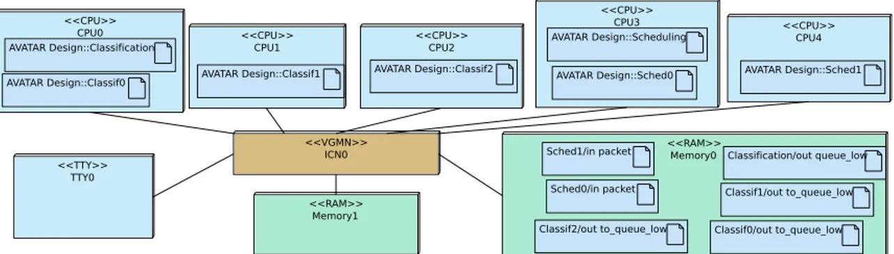
Allocation of tasks and channels onto the target MPSoC is explicitly captured within deployment diagrams. These diagrams contains hardware nodes (e.g., CPUs and memory banks) that can be cus-tomized with several parameters such as cache associativity, memory size, . . . . Software tasks are mapped onto the execution nodes of the platform, and channels between tasks are mapped onto the memories. Timers and interrupts are hidden, and are automatically added to the prototyping model during the deployment diagram transformation to SoCLib.
Figure 6 shows the deployment diagram, where each block representing either a classifier or a scheduler is mapped onto a separate processor. The
six channels are mapped to Memory0. The other memory banks represents on-chip packet storage.
The target architecture is based on a Virtual
Generic Micro Network(VGMN), which behaves as
two independent packet switched networks for com-mands and responses. The underlying simulation model of VGMN is cycle accurate bit accurate: it is based on SystemCASS [6]. The operating systems running on the processors is MutekH [4].
C. Experiments
For functional verification purpose, a C/POSIX code is first generated from software components only. As in former work, generated code is automat-ically enriched with backtracing information: this enables UML sequence diagrams displaying system
<<CPU>> CPU1 AVATAR Design::Classif1 <<CPU>> CPU3 AVATAR Design::Sched0 AVATAR Design::Scheduling <<CPU>> CPU0 AVATAR Design::Classif0 AVATAR Design::Classification <<TTY>> TTY0 <<VGMN>> ICN0 <<CPU>> CPU2 AVATAR Design::Classif2 <<RAM>> Memory0 Classif2/out to_queue_low Classif1/out to_queue_low Classif0/out to_queue_low Classification/out queue_low Sched0/in packet Sched1/in packet <<CPU>> CPU4 AVATAR Design::Sched1 <<RAM>> Memory1
Fig. 6. Deployment Diagram of the classification application
execution to be shown while executing the system on the local host (or on a target).
For virtual prototyping purpose, hardware is de-scribed on CABA (Cycle/Bit Accurate) level, thus with high precision at the price of rather slow simulation. We furthermore make the following assumptions. Only one level of interconnect be-tween hardware elements is considered, bounding the number of tasks and channels we can reasonably simulate to a few dozen. We perform experiments for three classifiers, three priority queues, and two schedulers.
Just like at the functional level, each SysML block is translated into on POSIX thread. Each threads is executed on one of the five powerPC405 processors. In the scope of our application, the channel memory is a potential contention point; channels locks are other potential contention points.
0 2000 4000 6000 8000 10000 0 50 100 150 200 250 300 cycles
mio. simulation cycles
transfer time spent in lock
Fig. 7. Transfer latency in priority queues
0 5 10 15 20 25 30 1x10⁶ 2x10⁶ 3x10⁶ 4x10⁶ 5x10⁶ 6x10⁶ 7x10⁶ 8x10⁶ 9x10⁶ 1x107 bytes simulation cycles Priority Queue0 Priority Queue1 Priority Queue2
Fig. 8. Fill state of the priority queues
We plot the fill state of the three priority queues for the first millin simulation cycles (see Figure 8). The channels never overflow, a maximum of 3 descriptors (24 byte) are simultaneously present in a channel, most of the time the cchannels are near empty (0 or 1 descriptor). We can also determine the latency of a transfer through the priority queues in the course of time (Figure 7).
Previous work showed that transfer latency and channel fill state vary more strongly for clustered platforms. Buses, bridges and crossbars can be customized at SysML level. The corresponding SoCLib models will allow us to address NUMA architectures in the near future: these architectures are indeed expected to provide better latency results but also more variation in the fill state of the channels [10].
VI. CONCLUSION ANDFUTUREWORK
This paper extends a UML/SysML virtual pro-totyping environment for embedded systems to SoCLib-based communication-bound platforms. A typical task farm case is used to explain modeling operators, the formal semantics and some prelimi-nary performance results.
Parallel classification is known to suffer from several major performance impediments, such as overflow of the input channels for high throughput, which can only be revealed once input and output hardware accelerators with parametrizable through-put are available. We cannot yet model these effects as our current modeling approach limits to the
softwarepart of the application running on general
purpose processors.
Also, we are working on a tool for better cap-turing latencies, and automatically evaluating them during the prototyping stage. That would enable to compare high-level simulation result - e.g., at partitioning - with results obtained with the cycle accurate bit accurate simulations, thus paving the way to design space exploration at different level of abstractions.
REFERENCES
[1] SoCLib consortium. SoCLib: an open platform for virtual prototyping of multi-processors system on chip (webpage). In http://www.soclib.fr.
[2] F. Balarin, Y. Watanabe, H. Hsieh, L. Lavagno, C. Passerone, and A. L. Sangiovanni-Vincentelli. Metropo-lis: An integrated electronic system design environment. IEEE Computer, 36(4):45–52, 2003.
[3] G. Batori, Z. Theisz, and D. Asztalos. Domain Specific Modeling Methodology for Reconfigurable Networked Sys-tems, pages 316–330. Springer, Berlin, Heidelberg, 2007. [4] A. Becoulet. Mutekh. http://www.mutekh.org.
[5] J. Bengtsson and W. Yi. Timed automata: Semantics, algorithms and tools. In Lecture Notes on Concurrency and Petri Nets, pages 87–124. W. Reisig and G. Rozenberg (eds.), LNCS 3098, Springer-Verlag, 2004.
[6] R. Buchmann and A. Greiner. A fully static scheduling approach for fast cycle accurate SystemC simulation of MPSoCs. In Proc. ICEEC, pages 35–39, Cairo, Egypt, Dec. 2007. IEEE.
[7] M. Di Natale, F. Chirico, A. Sindico, and A. Sangiovanni-Vincentelli. An mda approach for the generation of communication adapters integrating sw and fw components from simulink. In Int. Conf. on Model Driven Engineering Languages and Systems, pages 353–369. Springer, 2014.
[8] J. Eker, J. W. Janneck, E. A. Lee, J. Liu, X. Liu, J. Ludvig, S. Sachs, Y. Xiong, and S. Neuendorffer. Taming hetero-geneity - the ptolemy approach. Proceedings of the IEEE, 91(1):127–144, 2003.
[9] C. Erbas, S. Cerav-Erbas, and A. D. Pimentel. Multiob-jective optimization and evolutionary algorithms for the application mapping problem in multiprocessor system-on-chip design. IEEE Trans. on Evolutionary Comp., 10(3):358–374, 2006.
[10] Etienne Faure. Communications matérielles-logicielles dans les systèmes sur puce orientés télécommunications (HW/SW communications in telecommunication oriented MPSoC). PhD thesis, UPMC, 2007.
[11] A. Gamatié, S. L. Beux, É. Piel, R. B. Atitallah, A. Etien, P. Marquet, and J.-L. Dekeyser. A model-driven design framework for massively parallel embedded systems. ACM TECS, 10(4):39, 2011.
[12] D. Genius and L. Apvrille. Virtual yet precise prototyping : An automotive case study. In ERTSS’2016, Toulouse, Jan. 2016.
[13] D. Genius, E. Faure, and N. Pouillon. Mapping a telecom-munication application on a multiprocessor system-on-chip. In G. Gogniat, D. Milojevic, and A. M. A. A. Erdo-gan, editors, Algorithm-Architecture Matching for Signal and Image Processing, chapter 1, pages 53–77. Springer LNEE vol. 73, Nov. 2011.
[14] D. Genius, L. Li, and L. Apvrille. Model-Driven Perfor-mance Evaluation and Formal Verification for Multi-level Embedded System Design. In 5th International Conference on Model-Driven Engineering and Software Development, Porto, Portugal, Feb. 2017. INSTICC.
[15] K. Goossens, B. Vermeulen, and A. B. Nejad. A high-level debug environment for communication-centric debug. In Proceedings of the Conference on Design, Automation and Test in Europe, pages 202–207. European Design and Automation Association, 2009.
[16] G. Kahn. The semantics of a simple language for parallel programming. In J. L. Rosenfeld, editor, Information Processing ’74: IFIP Congress, pages 471–475. North-Holland, New York, NY, 1974.
[17] P. Lieverse, P. van der Wolf, K. A. Vissers, and E. F. Deprettere. A methodology for architecture exploration of heterogeneous signal processing systems. VLSI Signal Processing, 29(3):197–207, 2001.
[18] G. Pedroza, D. Knorreck, and L. Apvrille. AVATAR: A SysML environment for the formal verification of safety and security properties. In The 11th IEEE Con-ference on Distributed Systems and New Technologies (NOTERE’2011), Paris, France, May 2011.
[19] A. D. Pimentel, L. O. Hertzberger, P. Lieverse, P. van der Wolf, and E. F. Deprettere. Exploring embedded-systems architectures with artemis. IEEE Computer, 34(11):57–63, 2001.
[20] Sodius Corporation. MDGen for SystemC. http://sodius.com/products-overview/systemc.
[21] J. Vidal, F. de Lamotte, G. Gogniat, P. Soulard, and J.-P. Diguet. A co-design approach for embedded system modeling and code generation with UML and MARTE. In DATE’09, pages 226–231, April 2009.
[22] VSI Alliance. Virtual Component Interface Standard (OCB 2 2.0). Technical report, Aug. 2000.