(12) INTERNATIONAL APPLICATION PUBLISHED UNDER THE PATENT COOPERATION TREATY (PCT) (19)World Intellectual Property
Organization
InternationalBureau (10)International Publication Number
(43)International Publication Date
WO 2017/211555
Al
14 December 2017 (14.12.2017)
W ! P O
PCT
(51) International Patent Classification: (BE). PIEDBOEUF, Marie-Laure; Universite de Liege, HOIM 4/04(2006.01) H01M 4/587(2010.01) Department of Chemical Engineering, Ingenierie elec-H01M 4/36(2006.01) H01M 4/38(2006.01) trochimique, Allee du six Aout 11,Bat. B6, 4000 LIEGE H01M 4/485(2010.01) H01M 4/505(2010.01) (BE). JOB, Nathalie; Universite de Liege, Department of H01M 4/62(2006.01) H01M 4/525(2010.01) Chemical Engineering, Ingenierie electrochimique, Allee H01M 10/04(2006.01) H01M4/131 (2010.01) du six Aout 11,Bat. B6, 4000 LIEGE (BE).
H01M 10/54(2006.01) H01M 4/133(2010.01)
(81) Designated States (unless otherwise indicated,for every H01M 4/1393(2010 .01) H01M 4/136(2010.01)
kind of national protection available): AE, AG, AL, AM, H01M 4/1397(2010.01) H01M 4/1391(2010.01)
AO, AT, AU, AZ, BA, BB, BG, BH, BN, BR, BW, BY, BZ, H01M 4/58(2010.01) H01M 4/1395(2010.01)
CA, CH, CL, CN, CO, CR, CU, CZ, DE, DJ, DK, DM, DO, (21) International Application Number: DZ, EC, EE, EG, ES, FI, GB, GD, GE, GH, GM, GT, HN, PCT/EP20 17/06 1786 HR, HU, ID, IL, IN, IR, IS, JP, KE, KG, KH, KN, KP, KR, KW, KZ, LA, LC, LK, LR, LS, LU, LY, MA, MD, ME, MG, (22) International Filing Date:
MK, MN, MW, MX, MY, MZ, NA, NG, NI, NO, NZ, OM,
17May 2017 (17.05.2017)
PA, PE, PG, PH, PL, PT, QA, RO, RS, RU, RW, SA, SC, (25) Filing Language: English SD, SE, SG, SK, SL, SM, ST, SV, SY, TH, TJ, TM, TN, TR,
TT, TZ, UA, UG, US, UZ, VC, VN, ZA, ZM, ZW. (26) Publication Language: English
(84) Designated States (unless otherwise indicated,for every (30) Priority Data:
kind of regional protection available): ARIPO (BW, GH, 16173423.1 0 7 June 2016 (07.06.2016) EP
GM, KE, LR, LS, MW, MZ, NA, RW, SD, SL, ST, SZ, TZ, (71) Applicant: UNIVERSITE DE LIEGE [BE/BE]; Patent UG, ZM, ZW), Eurasian (AM, AZ, BY, KG, KZ, RU, TJ, Department, place du XX aout, 7, 4000 LIEGE (BE). TM), European (AL, AT, BE, BG, CH, CY, CZ, DE, DK, EE, ES, FI, FR, GB, GR, HR, HU, IE, IS, IT, LT, LU, LV, (72) Inventors: LEONARD, Alexandre; Universite de Liege, MC, MK, MT, NL, NO, PL, PT, RO, RS, SE, SI, SK, SM,
Department of Chemical Engineering, Ingenierie elec-trochimique, Allee du six Aout 11,Bat. B6, 4000 Liege
(54) Title: PROCESS TO PREPARE AN ELECTRODE FOR AN ELECTROCHEMICAL STORAGE DEVICE
- O. c rg A -Θ- discharge ( h · — · — — » « — — · — · — · — · — * — · — · — · — · — « — 150 100 m 50 10 15 20 CycleNumber Fig. 1
(57) Abstract: The invention is directed to a process to prepare an electrode for an electrochemical storage device by spraying an aqueous slurry composition comprising water, xanthan gum, a source of conducting carbon particles and an active material on an electrode base. The slurry may be made by first mixing solid xanthan gum with the conducting carbon particles and the active material and secondly adding water to the resulting mixture. Alternatively the slurry is obtained by mixing solid xanthan gum with a carbon-based
o
active material and adding water to the resulting mixture obtained.o
W O 2017/211555 A l
llll I I I I11
IIII
III
II II IIIIIII
III III
IITR), OAPI (BF, BJ, CF, CG, CI, CM, GA, GN, GQ, GW,
KM, ML, MR, NE, SN, TD, TG).
Declarations under Rule4.17:
— astoapplicant's entitlementtoapplyfor and be granted a patent(Rule 4.17(H))
PROCESS TO PREPARE AN ELECTRODE FOR AN ELECTROCHEMICAL STORAGE DEVICE
The invention is directed to a process to prepare an electrode for an electrochemical storage device. The invention is also directed to an electrochemical storage device which comprises such electrodes and to a method to reclaim valuable components of the
electrochemical storage device after use.
An example of a known electrochemical storage device are lithium ion batteries asfirst described in US4959281 consisting of Li intercalation compounds. The most widespread electrode preparation involves the use of organic binders as fluorine-based polymers, conducting carbon additive and organic solvents suchasN-methyl-2-pyrrolidone, as
described for example in patent CN101414693 and by Jae-Kwang Kim, Johan Scheers, Young- Jin Choi, Jou-Hyeon Ahn, Gil-Chan Hwang : Facile preparation of nanoporous and nanocrystalline LiFeP04with excellent electrochemical properties, RSC Adv., 2013, 3,
20836.
The use of these organic binder and solvent compounds asin the above described methods are disadvantageous because of environmental reasons. Another disadvantage is that the recovery of the current collectors after such batteries end-of-life requires the use of toxic organic solvents to dissolve electrode composites as for example described in
US20 13/0302226.
Methods using more environmentally friendly pathways, suchasreplacement of
organic binder and solvent compounds by water as solvent and water-compatible binders, like in US2013/0108776, also imply the use of binder in conjunction with one or more
dispersants, adding therefore a useless mass of additional ingredients which are not participating to the electrochemical reaction of the electrochemical storage device.
The object of the present invention is to provide a process to prepare an electrode for an electrochemical storage device which does not have one or more of the above disadvantages.
This object is achieved with the following process to prepare an electrode for an electrochemical storage device by spraying an aqueous slurry composition comprising water, xanthan gum, a source of conducting carbon particles and an active material on an electrode base to obtain a covered electrode base, wherein the slurry is obtained by one of the
following slurry preparation processes
(a)comprising of the following in-sequence steps wherein (ai) first solid xanthan gum
optionally adding active material to the resulting mixture in case active material was not added or not sufficiently added in step (ai) and (aiii) adding water to the resulting mixture obtained in step (ai) or (aii) such that the content of solids in the resulting aqueous slurry is
between 2 and25wt.%,
or (b) comprising of the following in-sequence steps wherein (bi) solid xanthan gum
ismixed with a carbon-based active material and (bii) adding water to the resulting mixture obtained in step (bi) such that the content of solids in the resulting aqueous slurryisbetween 3-12wt.%.
Applicants found that an electrode may be prepared by the described slurry preparation processes which does not use an environmental disadvantageous organic binder and solvent compound. The electrodes themselves have similar and sometimes better cycling properties
as compared with prior art electrodes obtainable by bar coating process involving the use of an organic binder and solvents. Furthermore an electrode is obtained which can be more easily recycled. In other words an electrode base made of metal or any other current conducting surface can be more easily reclaimed from an electrochemical storage device comprising the electrodes as obtainable by the process according to the invention.
The electrochemical storage device for which the electrode is prepared may be a supercapacitor, a sodium ion electrochemical storage device, a lithium ion electrochemical storage device and preferably a lithium ion electrochemical storage device. The below description ismainly directed to the preparation of an electrode for a lithium ion electrochemical storage device.
In slurry preparation processes (a) an active material is used. The choice of active material will depend on the type of electrode one wishes to prepare. When the electrode isan anode electrode for a lithium ion electrochemical storage device, the active material may be for instance a carbon based material, like for example porous carbons, carbon nanotubes, carbon black, graphene and graphite, Si-C composites, Sn-C composites, Sn orSiparticles,
Li.iTi5012isa preferred anode material since it exhibits enhanced safety due to zero strain (negligible volume change) during the Li intercalation-deintercalation processes, and consequently longer service life and shorter charging times. Li4Ti 0 i2can be prepared via various processes suchassolid state synthesis, hydrothermal synthesis, spray drying or sol-gel-synthesis, asfor example described in US20 15236345.
When the electrode is a cathode for a lithium ion electrochemical storage device, the active material may be selected from the group consisting of LiCo02, Li i02, LiMn204,
LiFeP0 4, LiMnP0 4, LiFexMni_
xP04(0<x<l), Li ixMn Coi_x_02,Lii+xN i Mn Coi_x__02, LiNi MnyCoAli_ _y_02,Lii+N iyMni_ Co 02, Cu2ZnSn(S, Se)4 . Phosphate-based cathodes, in particular LiFeP0 4is preferred since they exhibit enhanced stability, extended lifetime and overcome safety issues occurring upon overheating or overcharging.
The electrode base may be composed of any material which exhibits electronic
conductivity and does not undergo any oxidation or reduction at the operating voltages of the electrochemical storage device. Examples are metals, carbon foams, reticulated vitreous carbons, graphite foams or carbon-coated substrates. Preferred materials are carbon and/or nanotube-covered substrates or metals, for example copper, aluminium or stainless steel.
The source of conducting carbon particles asused in slurry preparation processes (a) are suitably Carbon Black particles, carbon nanotubes, graphene or a mixture thereof, conferring good electronic conductivities to the prepared electrodes. Preferably, high-purity carbon-black with low impurities contents and good electronic conductivity is used, like for instance Timcal Super C65 asobtained from Imerys Graphite & Carbon. The anode active material asused in slurry preparation processes (b) are carbon-based materials such as hard carbons or synthetic graphites, preferably graphite, a porous carbon and/or carbon nanotubes. The synthetic graphite particles preferably have particle sizes of between 0.1 and 10 µιη.
The xanthan gum isa polysaccharide as for example secreted by the bacterium
Xanthomonas campestris. The content of xanthan gum asreferred to in this description refers to the content of the polysaccharide in terms of solid matter expressed asweight percentage. The water asadded in the slurry preparation processes (a) and (b) is preferably ultra-pure water.
In a preferred embodiment, the mixing in step (ai) of solid xanthan gum with the source of conducting carbon and optionally the active material isperformed under a shear stress.
By shear stress one means a shear obtained in a mixing composition when using a mortar, a mill mixer, a ball milling device such as a planetary ball milling device.
The mixing of the solid compounds in step (ai) is therefore suitably performed by means of ball milling and preferably by planetary ball milling.
The process according to the invention advantageously provides a flowable aqueous slurry composition that can be sprayed, allowing a more accurate preparation of an electrode for electrochemical storage devices. Indeed the in-sequence steps of the process surprisingly provides a flowable and therefore sprayable composition whereas another sequence o f steps provides gelation of the composition.
Consequently, it isnow easier and more accurate to characterise an electrode by weighing the dried covered base and compare to the mass of the starting electrode base to finally obtain a measurement of the exact mass of active material involved in the electrode and characterise its electrochemical performance.
The process according to the invention surprisingly and advantageously also provides improved coating adhesion on its electrode base without surface treatment such ascorona treatment generally applied to raise surface energy of the surface.
In a further embodiment the slurryisobtained by slurry preparation process (a). In step (ai)or (aii) of such a process, the content of active material is suitably between 70 and
95wt.%, preferably between 70and 80wt.%, the content of solid xanthan gumissuitably between 1 and 10wt.%, preferably between 2 and 8 wt.% and the content of conducting carbon particles is suitably between 1 and25wt.%, preferably between 15 and 25wt.%. In such a process the active material may be added in a second step (aii) to the mixture obtained in step (ai).Thus the slurry isobtained by slurry preparation process (a) comprising the following steps wherein (ai) first the solid xanthan gumismixed with the conducting carbon particles, (aii) adding active material to the resulting mixture and (aiii) adding water to the resulting mixture obtained in step (aii), such that the total solid contents in water is between 2 and25wt.%. Applicants have found that such a process is suited for anode active materials, suchas Li.iTi5012 aswell as cathode active materials such as LiFeP04or LiCo0 2.
For active materials, like Li4TisOi2or LiCo02, that display very poor electronic
conductivities itmay be preferred to obtain the slurry by a slurry preparation process wherein the active material ismixed with the xanthan gum and conducting carbon additive in a first step.Thus such a modified process would comprise the following steps wherein (ai) first the solid xanthan gumismixed with the conducting carbon particles and active material and (aiii) adding water to the resulting mixture obtained in step (ai).
The slurry obtained by slurry preparation process (b)may be used to prepare electrodes based on active materials, such ashard carbons or graphite. The content of active material in process (b) can range between 70 and95wt.%, and preferably between 90 and95wt.%.
The obtained slurry of process (a) comprises between 2 and25wt.% of solids, suitably between 6 and 12wt.% of solids. The obtained slurry of process (b) comprises between 3 and
12 wt.% of solids, suitably between 7 and 10wt.% of solids. In combination with the xanthan gum a slurry would then be obtainable which can be sprayed upon an electrode base.
Sprayingmay be performed according to the well-known spraying techniques, wherein finely dispersed droplets of the slurry are formed in a spray. The droplets will deposit on the surface of the electrode base to form a covered electrode base. The thus obtained covered electrode baseissubsequently dried to obtain a dried covered electrode base.
Advantageously, the process according to the invention can be applied to all types of electrode base surfaces such as a planar or a curved surface, a rigid or a flexible surface.
Suitably the mass of the dried covered base is measured and compared to the mass of the starting electrode base to obtain a measurement for the amount of coatingasadded to the electrode base. The exact measurement of the mass of active material is important in order to know with precision the gravimetric capacity of the final anode or cathode.
Prior to using the electrodesaspart of an electrochemical storage device, the electrodes aresuitably dried at a low pressure at a temperature between 20 and 150 °C.
Theinvention is also directed towards an electrode comprising an electrode base and a sprayedcoating comprising of xanthan gum, a source of conducting carbon and an active material. The components of this electrode may beas described above and the electrode itself may be obtained by the process according to the invention. Such an electrode, which may be advantageously usedaspart of a lithium ion electrochemical storage device, a sodium-ion electrochemical storage device or a supercapacitor, isfound tobe recyclable.
Theinvention is also directed to a lithium ion electrochemical storage device
comprising the above described electrode or an electrode obtained by the process according tothe invention. The electrochemical storage device may further comprise of an electrolyte anda separator. The electrolyte and separator may be those known for lithium ion batteries. The separator may be a porous substrate having pores, and examples of the separator that can be used include (a) a porous separator having pores, (b) a porous separator on which a polymer coat layer is formed on one or both surfaces, or(c) a porous separator on which a porous resin coat layer containing inorganic ceramic powder is formed on the surface. The non-limiting examples of these separators include: a polypropylene, polyethylene, polyolefin or aramid porous separator; a separator coated with a polymer film or a gelling polymer coatinglayer for a solid polyelectrolyte or a gelatinous polyelectrolyte such aspolyvinylidene fluoride,polyethylene oxide, polyacrylonitrile and a polyvinylidene fluoride
hexafluoropropylene copolymer; and a separator coated with a porous film layer composed of a dispersant for an inorganic filler or an inorganic filler.
The electrolytic solution used in the present invention is not particularly limited, but for example,those in which a lithium salt dissolved as a supporting electrolyte in a nonaqueous
solvent can be used. Examples of the lithium salt include a lithium salt such asLiPFg, LiAsF6,L1BF4, LiSbF6,L1AICI4,L1CIO4,CF3SO3L1, C4F9SO3L1,CF3COOL1,
(CF3CO) NLi, (CF3S0 )2NLi and (C F S02)NLi orso. Especially preferably used are LiPFg, L1CIO4 and CF3SO3L1,which can easily dissolve in a solvent and exhibit a high dissociation degree. These can be used alone or by combining two or more thereof. The amount of the supporting electrolyte isusually 1 wt % or more, preferably 5 wt % or more, and usually 30wt % or less and preferably 20 wt % or less, with respect to the electrolytic solution. When the amount of the supporting electrolyte is too small or too large, the ion conductivity declines and the charge and discharge characteristics of the electrochemical storage device decline.
A solvent used in the electrolytic solution is not particularly limited as long as it dissolves the supporting electrolyte, however alkyl carbonates such asdimethyl carbonate (DMC), ethylene carbonate (EC), diethyl carbonate (DEC), propylene carbonate (PC), butylene carbonate (BC) and methyl ethyl carbonate (MEC) orso; esters such asγ -butyrolactone and methyl formate or so;ethers such as 1,2-dimethoxyethane and tetrahydrofuran orso; and sulfur-containing compounds such assulfolane and dimethylsulfoxide or somay be mentioned. Dimethyl carbonate, ethylene carbonate, propylene carbonate, diethyl carbonate and methyl ethyl carbonate are preferable because especially high ionic conductivity is easily obtained and the operating temperature range is wide. These can be used alone or by combining two or more thereof. In addition, an additive can also be used by adding into the electrolytic solution. As the additive, a carbonate
compound suchasvinylene carbonate (VC) or so is preferable.
Examples of the electrolytic solution other than the above include a gelatinous polymer electrolyte in which an electrolytic solution isimmersed with a polymer electrolyte suchas
polyethylene oxide and polyacrylonitrile, and an inorganic solid electrolyte such aslithium sulfide, Lil andL13N or so.
The method for producing a lithium ion electrochemical storage device of the present invention is not particularly limited. For example, the above negative and positive electrodes are stacked against each other via a separator and wound or folded according to the
electrochemical storage device shape to place into an electrochemical storage device container and the electrochemical storage device container is sealed after an electrolytic solution is poured into the electrochemical storage device container. Further, an expanded metal, an overcurrent preventing element such asa fuse or a PTC element and a lead plate
may be placed depending on the needs thereby the pressure increase inside the
electrochemical storage device and overcharge and overdischarge can also be prevented. The shape of the electrochemical storage device may be a stacking cell type, a coin type, a button type, a sheet type, a cylindrical type, a square type, a flat type or the like.
The electrode base may be reclaimed from the above described lithium ion
electrochemical storage device by disassembling the electrochemical storage device and contacting the separate electrodes with water to obtain an electrode base which does not have a sprayed coating comprising of xanthan gum, conducting carbon particles and an active material. Suitably the electrode base is agitated during contact with water, for example by stirring the water solution or by ultra-sound. The water can be common tap-water, or, if the active materials are to be recycled separately, preferably ultra-pure water should be used.
The invention shall be illustrated by the following non-limiting examples.
Example 1
This example describes the process of preparing various types of electrodes. 0.200g xanthan gum (Binder, Sigma Aldrich) and 0.800g Carbon Super C65 (Conducting Carbon, Timcal) were mixed in a planetary mill (Fritsch Monomill P6) in stainless-steel jars with 20 stainless-steel balls (diameter 10 mm). Mixing was performed at 400 rpm, 5 x 1 minute, 15 seconds pause and in reverse mode.
Then, 0 . 125 g of this mixture were put together with 0.375g of active material, either Li4Ti 0 i2(anode material, asprepared for all examples unless stated otherwise by the procedure described in Kiyoshi Nakahara, et al, Preparation of particulate Li.iTi5012having excellent characteristics as an electrode active material for power storage cells, Journal of Power Sources 117 (2003) 131-136) or LiFeP0 4(cathode material, Pholicat FE100 as
obtained from beLife), leading to a composition by weight percentage of75 : 20 : 5 (active material : conducting carbon : binder). This mixture was dried during 1 hour at 100°C. 3.6 g of MilliQ water were then added resulting in a slurry containing 12wt.% solids, followed by magnetic stirring during 3 hours at 1000rpm. The slurry was then sprayed on 20 pre-weighed current collector Cu disks in the case of anode materials (0 14mm, punched from a copper foil, MTI corp.), on pre-weighed current collector Al disks in the case of cathode materials (0 14mm, punched from an alimentary Reynolds Al foil)) and/or on pre-weighed current collector stainless-steel disks for both types of materials (0 15.5mm, MTI corp.) using an airbrush (Harder & Steenbeck Airbrush Evolution Silverline fPc, 0.4 mm nozzle and needle).
The coated disks were dried during 2 hours at ambient temperature and overnight at 60°C. The weight of active material was determined with very good accuracy (error lower than 1%)
upon weighing the electrodes after drying and subtracting the mass of the corresponding bare current collector disk. An average mass of active material of 2.2 mg/cm2was obtained
regardless the used active material. The obtained electrodes were then dried at 120°Cunder vacuum during 2 hours and transferred to an Ar- filled glove-box (MBraun) for making half-cell assemblies.
The electrochemical measurements were carried out in CR2032 coin cells, where the tested material acted ascathode and a Li-metal disk as anode. A Celgard®separator soaked with 80 ofLP71 ( 1M LiPF6 in Ethylene carbonate : Diethylcarbonate :
Dimethylcarbonate (EC:DEC:DMC) 1:1:1 weight ratios) or Ethylene carbonate
Diethylcarbonate (EC:DEC) 1:1 weight ratio electrolyte was placed in-between. Charge-discharge cycles were recorded up to rates of IOC (6minutes to fully charge the cell, 6 minutes to fully discharge the cell again) between 1.0 and2.5V (vs. Li+/Li) or 2.0 and 4.2 V
(vs. Li+/Li) for anode and cathode materials respectively with a Biologic VMP3 multichannel potentiostat or a Neware battery cycler at 25°C.
Example 2
Example 1 was repeated for preparing a graphite (anode material, KS6L, Timcal) covered electrode. In this example however no conducting carbon was added to the mixture. Briefly, 0.025g of xanthan gum (Binder, Sigma Aldrich) was mixed with 0.475g graphite (KS6L, Timcal), leading to a composition having a weight percentage of95wt.% graphite and 5 wt.% xanthan gum. This mixture was dried during 1 hour at 100°Cand 4.6 g of MilliQ water was subsequently added resulting in a slurry consisting of9.8 wt.% solids. The next steps were asin Example 1. An average mass of active material of3.6 mg/cm2on the electrode was obtained.
Example 3 (Comparison)
This example describes the preparation of LTO/Cu electrodes by means of a bar coater following a widely used conventional method. Li.iTi5012 (LTO) (anode material, asprepared for all examples unless stated otherwise by the procedure described in Kiyoshi Nakahara, et al, Preparation of particulate Li.iTi5012having excellent characteristics as an electrode active material for power storage cells, Journal of Power Sources 117 (2003) 131-136) as alsoused in Example 1, was dispersed in an organic solvent (NMP, N-methyl-2-pyrrolidone) with
PVDF (polyvinylidene fluoride) asa binder. The chosen composition by mass was: 75wt.% LTO, 10 wt.% PVDF, 15wt.% Conducting Carbon (Super C65, Timcal). The obtained organic slurry was coated on a Cu-foil by bar-coater at ambient temperature. This foil was then dried at 60°C and 14-mm electrodes were punched from this coating. The mass of active material was determined upon weighing these electrodes and subtracting the average mass of bare Cu-disks of the same size.
Example 4
In this example the cycling performance atC/5 inhalf-cells of LTO (Li4TisOi2, anode material) on a Cu disc according to the invention andasobtained in Example 1 were
compared to the cycling performance atC/5 for the LTO/Cu disc asobtained by means of bar coater in Example 3 .
Galvanostatic cycling was performed at a rate ofC/5 (5hours needed to fully charge the cell, 5 hours to fully discharge the cell).
Figure 1 shows the charge and discharge specific capacities asa function of cycle number and the horizontal dotted line indicates the theoretical specific capacity of the active material for the sprayed LTO/Cu electrode of Example 1 .The specific capacity after 20 cycleswas 163 mAh/g.
Figure 2 shows the charge and discharge specific capacities asa function of cycle number and the horizontal dotted line indicates the theoretical specific capacity of the active material for the bar coater LTO/Cu electrode of Example 3 .The specific capacity after 20 cycleswas 166mAh/g.
This experiment shows that the specific capacity after 20 cycles of the sprayed LTO/Cu electrode of Example 1 is very close to that of the bar coater LTO/Cu electrode of Example3,
and the cycling stability is the same. The observed differences cannot be consideredas
significant owing to the errors occurring on the mass determinations of electrodes obtained by the organic bar-coating process.
Example 5
In this example the cycling performance at variable rates in half-cells of LTO (Li4Ti50i2, anode material) on a Cudisc according to the invention and asobtained in Example 1 were compared to the cycling performance at variable rates for the LTO/Cu disc
Galvanostatic cycling was performed first at a rate ofC/5 (5hours needed to fully charge the cell, 5 hours to fully discharge the cell) for a given number of cycles, followed by cycling at higher rates (C/2, 1C,2C, 5C, IOC and back to C/5), for 10 cycles at each rate.
(IOC : 6 minutes needed to fully charge the cell, 6 minutes to fully discharge the cell). Figure 3 shows the charge and discharge specific capacities as a function of cycle number and the horizontal dotted line indicates the theoretical specific capacity of the active material for the sprayed LTO/Cu electrode of Example 1 .Figure 4 shows the charge and
discharge specific capacities asa function of cycle number and the horizontal dotted line indicates the specific theoretical capacity of the active material for the bar coater LTO/Cu electrode of Example 3 .
The specific capacity per cycle is also listed in the below Table 1.
Table 1
The global behavior isthe same for the electrodes of Example 1 (aqueous slurry) and Example 3 (organic slurry). The comparison of specific capacities reported in the Table 1 shows that the performances are somewhat lower in the case of the aqueous coatings, especially at high rates (5C and IOC). Full recovery of specific capacity atC/5 after cycling at high rates isobserved in both cases.
Example 6
Example 6 shows the cycling performance in half-cells of LFP (LiFeP04, cathode material, Pholicat FE100, beLife) at variable rates for aqueous sprayed slurries, with different contents in active material.
Two electrodes were prepared according to the procedure of Example 1:75wt.% LFP, 5w t .% xanthan gum, 20 wt.% Conducting Carbon (Super C65, Timcal) and70wt.% LFP, 5 wt.% xanthan gum,25wt.% Conducting Carbon (Super C65, Timcal). The fraction of total solids in water was 12 wt.%. The obtained aqueous slurry was then sprayed at ambient temperature on pre-weighed 14-mm Al-disks. The electrodes were weighed after drying at 60°C, allowing for the precise determination of the mass of active material.
Galvanostatic cycling was performed first at a rate ofC/5 (5hours needed to fully charge the cell, 5 hours to fully discharge the cell) for a given number of cycles, followed by cycling at higher rates (C/2, 1C,2C, 5C, IOC),with 10 cycles of charge-discharge at each rate. This procedure was repeated 3 times on the same cell.
Figure 5 shows the charge and discharge specific capacities asa function of cycle number for the electrode with 75wt.% LFP and Figure 6 shows the charge and discharge specific capacities as a function of cycle number for the electrode with 70wt.% LFP.
For both contents of LFP, stable cycling isobserved up to 2C (30 minutes needed to fully discharge the cell,30minutes to fully charge again), with high values of specific capacities. Superior performances in terms of capacity at high rates are obtained when the content of LFP decreases from75to70wt.%, i.e.when the relative quantity of conducting carbon is increased.
In each case, the specific capacities are recovered after cycling at very high rates, indicating the stability of the coatings.
Example 7
Example 7 shows the cycling performance in a half-cell of Graphite (KS6L, anode material, Timcal) atC/5 for an aqueous sprayed slurry. The electrode was prepared as
described in Example 2 on 14-mm Cu-disks. The horizontal dotted line indicates the theoretical specific capacity of the active material for the sprayed Graphite/Cu electrode of Example 2 .
Galvanostatic cycling was performed at a rate ofC/5 (5hours needed to fully charge the cell, 5 hours to fully discharge the cell).
Figure 7 and the Table 2 below show the charge and discharge specific capacities asa function of cycle number and the dotted line indicates the theoretical specific capacity of the active material.
(mAh/g) 1 320 10 339 25 340 50 336 75 324 100 317 Table 2
A specific capacity of about 340 mAh/g, which remains stable for 50cycles, isobtained for this coating, which corresponds to 91% of the theoretical specific capacity of graphite. A slow decayisthen observed, which could be attributed to the fact that no conducting carbon was added to the solid mixture.
Example 8
In this example the cycling performance at variable rates in half-cells of LTO (Li4Ti50i2, anode material) on a Cu disc according to the invention were compared to the cycling performance at variable rates for the LTO/Cu discasobtained by means of bar coater in Example 3 .
The LTO (Li4Ti 0 i2, anode material) on a Cu disc electrode was prepared according to Example 1, except in that the active material is directly mixed with the conductive carbon and the binder in weight percentages of80 :15 : 5 or 75 :20 : 5 (active material : conducting carbon : xanthan gum). This mixture isdried during 1 hour at 100°C and then subjected to planetary milling following the same procedure as described for Example 1,allowing for a more intimate contact between the components of the solid mixture. The latter is then dispersed in MilliQ water (12wt.%> solids), followed by magnetic stirring and spraying at
ambient temperature on pre-weighed 14-mm Cu-disks. The electrodes were weighed after drying at 60°C, allowing for the precise determination of the mass of active material.
Galvanostatic cycling was performed first ata rate ofC/5 (5hours needed to fully charge the cell, 5 hours to fully discharge the cell) for a given number of cycles, followed by cycling at higher rates (C/2, 1C,2C, 5C, IOC and back to C/5), for 10 cycles at each rate.
(IOC: 6 minutes needed to fully charge the cell, 6 minutes to fully discharge the cell) Figure 8 shows the charge and discharge specific capacities asa function of cycle number of the LTO (L i O , anode material) on a Cu disc electrode prepared according to
the procedure of the above paragraph and the horizontal dotted line indicates the theoretical specific capacity of the active material. Figure 9 shows the charge and discharge specific capacitiesasa function of cycle number of the LTO/Cu electrode asobtained by means of bar coater (procedure of Example3) and the horizontal dotted line indicates the theoretical
specific capacity of the active material.
The global behavior isthe same for the aqueous and organic slurries. Improved specific capacities for each rate of cycling are however obtained in the case of the aqueous pathway with xanthan gumasa binder.
The comparison of these results with Example 5 suggests that the optional addition of the active material (step aii) to the xanthan gum - conducting carbon mixture prior to ball-milling is more adapted for insulating active materials. Indeed, the ball-ball-milling step of all the components will lead to an enhanced interaction between the LTO active material and the conducting carbon additive, which will result in enhanced cycling performances, especially at high rates, favoring the electron transfers.
Example 9
Example 9 illustrates the cycling performance in half-cells of LTO (Li4TisOi2, anode material) at 1C for aqueous sprayed slurries with stainless-steel disksas current collectors.
The LTO (Li4Ti 0 i2, anode material) on a stainless-steel (SS) disc electrode was prepared according to Example 1, except in that the active material is directly mixed with the conductive carbon and the binder in weight percentages of80 :15 : 5 or 75 : 20 : 5 (active material : conducting carbon : xanthan gum). This mixture is dried during 1 hour at 100°C and then subjected to planetary milling following the same procedure as described for Example 1, allowing for a more intimate contact between the components of the solid mixture. The latter is then dispersed in MilliQ water (12 wt.% solids), followed by magnetic stirringand spraying at ambient temperature on pre-weighed 15.5-mm SS-disks. The
electrodes were weighed after drying at 60°C, allowing for the precise determination of the mass of active material.
Galvanostatic cycling was performed at a rate of 1C ( 1hour needed to fully charge the cell, 1 hour to fully discharge the cell).
Figure 10 shows the charge and discharge specific capacities asa function of cycle number and the horizontal dotted line indicates the theoretical specific capacity of the active material. An excellent cycling stability with a stable value of specific capacity of 161 mAh/g up to 150 cycles atleastwas recorded in this case.
Example 10
Example 10 shows the cycling performance in half-cells of LCO (LiCo02, cathode material, Sigma-Aldrich) at C/5 and C/2 for aqueous sprayed slurries, with different contents in active material.
For the dispersion in water, the procedure of Example 1 was first used. No cycling of half-cells could be performed in this case, probably due to improper contact between the active material and the conducting carbon additive.
For that reason the active material isdirectly mixed with the conductive carbon and the binder in weight percentages of75wt.% LCO, 5 wt.% xanthan gum, 20 wt.% conducting carbon (Super C65, Timcal) and70wt.% LCO, 5 wt.% xanthan gum,25wt.% conducting carbon (Super C65, Timcal). This mixture is dried during 1 hour at 100°Cand then subjected toplanetary milling following the same procedure asdescribed for Example 1,allowing for a more intimate contact between the components of the solid mixture. The latter is then
dispersed in MilliQ water (12 wt.% solids), followed by magnetic stirring and spraying at ambient temperature on pre-weighed 14-mm Al-disks. The electrodes were weighed after drying at 60°C, allowing for the precise determination of the mass of active material.
Galvanostatic cycling was performed first for 100 cycles ata rate ofC/5 (5hours needed to fully charge the cell, 5 hours to fully discharge the cell), followed by cycling at C/2
(2hours needed to fully charge the cell,2 hours to fully discharge the cell).
Figure 11 shows the charge and discharge specific capacities asa function of cycle number for the electrode derived from the 75wt.% LCO, 5 wt.% xanthan gum, 20 wt.% conducting carbon mixture. Figure 12 shows the charge and discharge specific capacities as a function of cycle number for the electrode derived from the70wt.% LCO, 5 wt.% xanthan gum,25wt.% conducting carbon mixture..
For both contents of LCO, the specific capacity tends to decrease with cycling. A better stability and higher specific capacity values are observed when the relative amount of
conducting carbon is increased (70 wt.% of LCO), demonstrating the importance of the contact between the additive and the active material.
Although the cycling stability isnot optimized, this example nevertheless demonstrated the possibility of coating another cathode material than LFP by aqueous processing, with xanthan gumas a binder. Improved performances are expected upon using modified or pre-treated LCO.
This example also demonstrates the benefits of the modified procedure when the active materials used display an insulating character.
Example 11
Li4Ti 0 i2coated on Cu andSS electrodes as well asLiFeP04coated on Al andSSelectrodes, prepared asdescribed in the above Examples 4, 5, 6,by the aqueous pathway according to the processes of this invention, were recovered after cell disassembly. The electrodes were
covered with3.5 ml of deionized water without any prior treatment. After contacting by manual stirring or ultrasounds for 10 seconds at ambient temperature, the coatings separated from the current collectors, allowing for the recovery of clean metal bases (Cu, Al orSS).
This example demonstrates the benefits of the invention by the fact that a non-toxic solvent (water) can easily be used to recover clean metal current collectors after batteries end-of-life.
Example 12
Example 12shows a preferred embodiment wherein a shear stress is applied to the solid components prior to the slurry preparation to obtain a flowable sprayable solution
In a first instance, 0.025g of Xanthan gum binder, i.e. the quantity corresponding to that described in Example 1,was dissolved in 3.6g of MilliQ water, followed by magnetic stirring during 3 hours at 1000rpm.A gel-like mixture is formed asillustrated in Figures 13A and B, which cannot be processed further, e.g. by spraying.
On the opposite, if the xanthan gum binder is ball-milled with a carbon additive, asreported in Example 1,the resulting solid mixture can be dispersed in water in presence of a cathode or anode active material, leading to a low viscosity sprayable solution.
In a second instance, 0.025g xanthan gum binder, 0.1OOg of Carbon SuperC65 (Conducting Carbon,Timcal) and 0.375g of LiFeP04(cathode material, Pholicat FE100as obtained from beLife), were hand-mixed in a vial, leading to a composition by weight percentage of75 : 20
: 5 (active material : conducting carbon : binder). To this mixture, 3.6 g of MilliQ water were then added, resulting in a slurry containing 12 wt.% solids, followed by magnetic stirringduring 3 hours at 1000rpm. A gel-like mixture is formed as illustrated in Figure 13
C&D,which cannot be further processed either by spraying or by bar-coater in opposition to the process according to the invention, wherein a flowable sprayable solution is obtained.
Example 13 comparison with US US2013/0108776A1
This example shows the cycling performance atC/5 inhalf-cellsof LTO ( Ti O , anode material) on a Cu discand LFP (LiFeP04, cathode material, Pholicat FE100, beLife) on an Al disk, according to the invention and asobtained in Example 1. Charge and discharge were performed at this rate during50cycles to evaluate the stability over time.
As shown from Figure 14 andTable 3,the specific capacities remain stable for both of the investigated active materials when cycling is performed during50 cycles at a rate ofC/5.
This isopposite to the observations described in US2013/0108776A1, wherein
polyethyleneimine is needed asa dispersant for slurry preparation. In this latter case, the specific capacity of LiFeP04cathode materials decreases with cycling when no
polyethyleneimine is added to the mixture. This difference proves that the process according tothe invention can lead to electrodes (anodes and cathodes) with a good cycling stability, without need of an additional dispersant in the mixture.
Table 3
Example 14
Example 14 shows the cycling performance in half-cells of LFP (LiFeP04, cathode material, Pholicat FE100, beLife) at a rate ofC/5 for aqueous sprayed slurries on Al disks, with different contents of Multiwalled Carbon Nanotubes (MWCNT, NC-7000, Nanocyl) as
The electrodes were prepared according to the procedure of Example 1: 75 wt.% LFP, 5
w t .% xanthan gum, 20 wt.% Conducting additive. The classically used Conducting Carbon additive (Super C65, Timcal) was in this case replaced by 2, 15,50 and 100 wt.% carbon nanotubes. The fraction o f total solids in water was 12wt.%. The obtained aqueous slurry was then sprayed at ambient temperature on pre-weighed 14-mm Al-disks. The electrodes were weighed after drying at 60°C, allowing for the precise determination of the mass of active material.
Galvanostatic cycling was performed during 50 cycles at C/5 (5 hours needed to fully charge the cell, 5 hours to fully discharge the cell).
Figure 15 represents the charge and discharge specific capacities as a function of cycle number and Table 4 shows the discharge capacity at cycle 50 for each composition.
Table 4
Stable cycling is observed at C/5 whatever the contents in carbon nanotubes as a conducting carbon additive. Indeed, even with full replacement of the classically used Super C65, i.e. 10 0 % CNT, similar values of capacities are obtained for this cycling. The values of specific discharge capacity also remain in the same range after 50 cycles, with values
comprised between 146 and 150 mAh/g. These results prove that the procedure presented here is compatible with the dispersion of multiwalled carbon nanotubes in aqueous slurries for Li-ion battery electrodes preparation.
Example 15
Example 15 shows the cycling performance in half-cells of LTO (L i O , anode material) at a rate of C/5 for aqueous sprayed slurries on Cu discs, with different contents of Multiwalled Carbon Nanotubes (MWCNT, NC-7000, Nanocyl) as a conducting additive.
The electrodes were prepared according to the procedure of Example 1: 75 wt.% LTO, 5w t .% xanthan gum, 20 wt.% Conducting additive. The classically used Conducting Carbon additive (Super C65, Timcal) was in this case replaced by 2, 15,50 and 100 wt.% carbon nanotubes. The fraction o f total solids in water was 12wt.%. The obtained aqueous slurry was then sprayed at ambient temperature on pre-weighed 14-mm Cu-disks. The electrodes were weighed after drying at 60°C, allowing for the precise determination of the mass of active material.
Galvanostatic cycling was performed during 50 cycles at C/5 (5 hours needed to fully charge the cell, 5 hours to fully discharge the cell).
Figure 16 represents the charge and discharge specific capacities as a function of cycle number and Table 5 shows the discharge capacity at cycle 50 for each composition.
Table 5
Stable cycling is observed at C/5 whatever the contents in carbon nanotubes as a conducting carbon additive. Indeed, even with full replacement of the classically used Super C65, i.e. 10 0 % CNT, similar values of capacities are obtained for this cycling. The values of specific discharge capacity also remain in the same range after 50 cycles, with values
comprised between 147 and 159mAh/g. These results prove that the procedure presented here is compatible with the dispersion of multiwalled carbon nanotubes in aqueous slurries for Li-ion battery electrodes preparation.
Example 16
This example illustrates the improved behavior in terms of adhesion of the coatings obtained by the process according to the invention. Three coatings have been prepared for an anode active material (LTO, Ti O , anode material on a Cu foil according to the invention and
asobtained in Example 1. Two different coating techniques have been used, namely bar-coater and manual spray. The classical composition made of PVDF binder in NMP solvent has also been compared with the aqueous pathway using XG as a binder. No further treatment was applied to the substrates prior to the coatings. This is opposite to US2013/0108776A1, where a surface treatment, e.g. plasma corona treatment isapplied in order to raise the surface energy of the surface to at least the surface tension of the mixed dispersion.
The adhesion has been tested for three types of coatings in each case by the use of the ASTM D3359-97 procedure. This test is based on the application of a force or an energy to separate two materials linked by a common surface. Adhesive paper is used to peel off the coating with an angle of 180°.
In the present case, the adhesion was qualitatively evaluated upon observation of the substrate
aswell asof the adhesive paper after the test.
Figure 17 shows adhesion results in different conditions for LTO active material on a copper foil. On the left sideisshown a picture of the copper foil after the adhesion test and on the right side a picture of the corresponding adhesive paper after the test.
The results clearly show that the process according to the invention using water and manual sprayascoating method displays the better behavior in terms of adhesion when compared with another coating technique (bar-coater) or with another ink preparation process (NMP+PVDF). Indeed, more coating remains present on the copper foil when the process according to the invention is used, and less material is seen on the adhesive paper in this case. This experiment demonstrates that the spraying technique leads to distinguished features in comparison to the bar-coating process, in addition to the fact that the water-based slurry making use of xanthan gum also shows superiority in terms of adhesion in comparison to the organic pathway.
Example 17
Example 17 shows the cycling performance at C/10 for 20 cycles and at C/2 for 80
cycles of a full Li-ion cell comprising an anode based on LTO (Li.iTi5012, anode material) on a Cu disc and a cathode based on LFP (LiFeP04, cathode material, Pholicat FE100, beLife) on an Al disk, according to the invention and asobtained in Example 1. Both electrodes were assembled in a CR2032 coin cell, with a Celgard®separator soaked with 80 of LP71 ( 1M LiPF6in Ethylene carbonate : Diethylcarbonate : Dimethylcarbonate (EC:DEC:DMC) 1:1:1 weight ratios) electrolyte was placed in-between. The charge-discharge cycles were recorded between 1.0and2.5 V (vs. Li+/Li) with a Biologic VMP3 multichannel potentiostat or a Neware battery cycler at 25°C.
As shown from Figure 18 and Table 6,a good cycling stability is recorded either at a rate of C/10 (10 hours to fully charge the cell, 10hours to fully discharge it) aswell as at C/2. The specific capacity of the cellisgiven as a function of the mass of LFP-cathode material. In this latter case, the specific capacity of the full cell stabilizes at ~ 115 mAh/g LFP, i.e. 115 mAh per gram of LFP present at the cathode.
These results indicate that the process described in the invention can lead to electrodes (anodes and cathodes) that work well in a Li-ion full cell, with good cycling stability.
Table 6
Example 18
This Example shows the cycling performance at C/10 for 20 cycles and at C/2 for80
a Cu disc and a cathode based on LFP (LiFeP04, cathode material, Pholicat FE100, beLife) on an Al disk, according to the invention and asobtained in Examples 14 and 15. In this case, for both the electrodes, the conducting carbon additive was totally replaced with multiwalled carbon nanotubes (Nanocyl NC-7000). Both electrodes were assembled in a CR2032 coincell,with a Celgard®separator soaked with 80 ofLP71 ( 1M LiPF
6 in Ethylene carbonate : Diethylcarbonate : Dimethylcarbonate (EC:DEC:DMC) 1:1:1 weight ratios) electrolyte was placed in-between. The charge-discharge cycles were recorded between 1.0and2.5 V(vs. Li+/Li) with a Biologic VMP3 multichannel potentiostat or a Neware battery cycler at 25°C.
As shown from Figure 19 and Table 7,a good cycling stability is recorded either at a rate of C/10 (10 hours to fully charge the cell, 10hours to fully discharge it)aswell as at C/2. The specific capacity of the cell isgiven as a function of the mass of LFP-cathode material. In this latter case, the specific capacity of the full cell stabilizes at -105 mAh/g LFP, i.e. 115 mAh per gram of LFP present at the cathode
These results indicate that the process described in the invention can lead to electrodes (anodes and cathodes) bearing only multiwalled carbon nanotubes as a conducting additive that work well in a Li-ion full cell, with good cycling stability. The performances remain comparable to those recorded for a full cell assembled from electrodes prepared according to the invention and asdescribed in Example 1, with Timcal Super C65 as a conducting
additive.
Example 19
In Example 19the cycling performance atC/5 in half-cells of LTO (as-prepared
particulate L i O , anode material) on a Cu disc according to the invention andasobtained in Example 1were compared to the cycling performance at C/5 for a commercial LTO (Sigma-Aldrich, Lithium Titanate, Spinel, >99%) on a Cu disc, processed in the same wayas
described in Example 1.
Galvanostatic cycling was performed at a rate ofC/5 (5hours needed to fully charge the cell,5hours to fully discharge the cell).
Figure20 shows the charge and discharge specific capacities asa function of cycle number and the horizontal dotted line indicates the theoretical specific capacity of the active material for the sprayed commercial LTO/Cu electrode, which can be compared with the sprayed LTO/Cu electrodeasobtained from Example 1andillustrated in Figure 1 .
The specific capacity in the present case after20 cycles was 164mAh/g, the same value
asfor the as-prepared particulate LTO/Cu electrode obtained from example 1 (163 mAh/g). The specific capacity per cycle is also listed in the below Table8 .
Table 8
The global behavior isthe same for the electrodes of Example 1(as-prepared
particulate LTO) and Example 19 (commercial LTO). The comparison of specific capacities reported in the Table 8shows that the performances are identical, whatever the origin of the used anode active material.
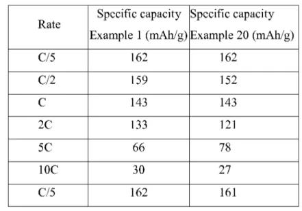
Example20
In this example the cycling performance at variable rates in half-cells of LTO (as-prepared particulate Li4TisOi2, anode material) on a Cu disc according to the invention andas
obtained in Example 1 were compared to the cycling performance at variable rates for a commercial LTO (Sigma-Aldrich, Lithium Titanate, Spinel, >99%) on a Cu disc, processed in the same wayas described in Example 1.
Galvanostatic cycling was performed in both cases first at a rate ofC/5 (5hours needed tofully charge thecell, 5 hours to fully discharge the cell) for a given number of cycles, followed by cycling at higher rates (C/2, 1C,2C, 5C, IOC and back to C/5), for 10 cycles at each rate. (IOC : 6 minutes needed to fully charge the cell, 6 minutes to fully discharge the cell).
Figure2 1shows the charge and discharge specific capacities asa function of cycle number and the horizontal dotted line indicates the theoretical specific capacity of the active material for the sprayed commercial LTO/Cu electrode, which can be compared with the sprayed LTO/Cu electrodeasobtained from Example 1 and illustrated in Figure3 .
The specific capacity per cycle is also listed in the below Table9 .
Table 9
The global behavior isthe same for the electrodes of Example 1 (as-prepared
particulate LTO) and Example 20 (commercial LTO). The comparison of specific capacities reported in the Table 9 shows that the performances are in the same range, whatever the origin of the used anode active material. Full recovery of specific capacity at C/5 after cycling at high rates is also observed in both cases.
CLAIMS
1. Process to prepare an electrode for an electrochemical storage device by spraying an aqueous slurry composition comprising water, xanthan gum, a source of conducting carbon particles and an active material on an electrode base to obtain a covered
electrode base, wherein the slurry isobtained by one of the following slurry preparation processes
(a) comprising of the following in-sequence steps wherein (ai) first solid xanthan gum
ismixed with the conducting carbon particles and optionally the active material, (aii) optionally adding active material to the resulting mixture in case active material was not added or not sufficiently added in step (ai) and (aiii) adding water to the resulting mixture obtained in step (ai) or (aii) such that the content of solids in the resulting aqueous slurry isbetween 2 and 25wt.%,
or (b) comprising of the following in-sequence steps wherein (bi) solid xanthan gum is
mixed with a carbon-based active material and (bii) adding water to the resulting mixture obtained in step (bi) such that the content of solids in the resulting aqueous slurry isbetween 3-12 wt.%.
2 .Process according to claim 1,wherein the mixing in step (ai) of xanthan gum with the conducting carbon particles and optionally the active material is performed under shear stress.
3 . Process according to claim 1 or2,wherein the electrode is an anode and the active material isselected in the group consisting of a carbon based material, Si-C composites,
Sn-C composites, Sn or Siparticles, LiTi0 2or Li4Ti 0 i2
4 . Process according to claim 3,wherein the active material is
5 . Process according to claim 1 or2,wherein the electrode is a cathode and the active material isselected from the group consisting of LiCo0 2, Li i02, LiMn204, LiFeP0 4, LiMnP0 4, LiFexMni_xP04, Li xMn Coi_x_ 02,Lii+N i Mn Coi_ _ _02,
LiNi Mn Co Ali_ _ _02,Lii+N i Mni_ Co 02, Cu2ZnSn(S, Se)4.
7 . Process according to any one of claims 1-6,wherein the electrode baseiscomposed of a metal or carbon and/or nanotube-covered substrates.
8 . Process according to any one of claims 1-7,wherein the slurry is obtained by slurry preparation process (a)and wherein in step (ai) or (aii) the content of active material is between 70and 95wt.%, the content of solid xanthan gumisbetween 2 and 8 wt.% and the content of the source of conducting carbon particles isbetween land 25wt.%.
9 . Process according to any one of claims 1-8,wherein the slurryisobtained by slurry preparation process (a) comprising the following steps wherein (ai) first the solid xanthan gumismixed with the conducting carbon particles, (aii) adding active material to the resulting mixture and (aiii) adding water to the resulting mixture obtained in step
(aii).
10. Process according to any one of claims 1-8,wherein the slurryisobtained by slurry preparation process (a) comprising the following steps wherein (ai) first the solid xanthan gumismixed with the conducting carbon particles and active material and (aiii) adding water to the resulting mixture obtained in step (ai).
11. Process according to anyone of claims 2-10 wherein the mixing in step (ai) is performed by planetary ball milling.
12. Process according to any one of claims 1-3 or 7,wherein the slurry containing carbon based active materials isobtained by slurry preparation process (b).
13. Process according to claim 12,wherein the carbon-based active material isgraphite, a porous carbon and/or carbon nanotubes.
14. Process according to any one of claims 1-13,wherein the covered electrode base is dried to obtain a dried covered base.
15. Process according to claim 14,wherein the mass of the dried covered electrode base is measured and compared to the mass of the starting electrode base to obtain an accurate
measurement for the amount of coating as added to the electrode base with less than 1%
error.
16. Electrode comprising an electrode base and a sprayed coating comprising of xanthan gum, optionally a source of conducting carbon and an active material.
17. Electrochemical storage device comprising an electrode according to claim 16 obtained by a process according to anyone of claim 1-15.
18. Process to recover an electrode according to claim 16,wherein the electrode is
contacted with water to obtain an electrode base which does not have a sprayed coating comprising of xanthan gum, conducting carbon particles and an active material.
A .CLASSIFICATION OF SUBJECT MATTER
INV. H01M4/04 H01M4/36 H01M4/485 H01M4/62 H01M10/04
H01M10/54 H01M4/1393 H01M4/1397 H01M4/58 H01M4/587
ADD. H01M4/38 H01M4/505 H01M4/525 H01M4/131 H01M4/133
According to International Patent Classification (IPC) or tobothnationalclassification andIPC
B. FIELDS SEARCHED
Minimumdocumentation searched (classification system followed by classification symbols) H01M
Documentationsearched other than minimum documentation to the extent that such documents are includedinthe fields searched
Electronicdata base consulted during the international search (name of data base and, where practicable, search terms used)
EPO-Internal , WPI Data
C.DOCUMENTS CONSIDERED TO BE RELEVANT
Category* Citationof document, with indication, where appropriate, of the relevant passages Relevant to claimNo.
US 2013/108776 A l (LI JIANLIN [US] ET AL) 16,17
2 May 2013 (2013-05-02) paragraphs [0005], [0007] - [0010], 1-15,18 [0012], [0088], [0089], [0090], [0098] , [0114] US 2012/264022 A l (H0S0E AKIHISA [JP] ET 1-15 AL) 18 October 2012 (2012-10-18) paragraphs [0059] , [0060] US 2009/220678 A l (K0N0 MICHIYUKI [JP] ET 1 1 AL) 3 September 2009 (2009-09-03) paragraph [0044] E P 2 306 583 A l (SUMITOMO CHEMICAL CO 18 [ P]) 6 April 2011 (2011-04-06) paragraphs [0012] , [0013]
□
Furtherdocuments are listedinthe continuation of BoxC . Seepatent family annex. * Special categories of cited documents :"T" later document published after the international filing date or priority dateand notinconflict with the application but cited to understand
"A" document defining the general state of the art whichisnot considered the principle or theory underlying the invention to be of particular relevance
"E" earlier application or patent but published on or after the international "X" document of particular relevance; the claimed invention cannot be filingdate considered novel or cannot be considered to involveaninventive
"L" documentwhich may throw doubtsonpriority claim(s) orwhich is stepwhenthe documentistaken alone
citedto establish the publication date of another citation or other "Y" document of particular relevance; the claimed invention cannot be special reason(asspecified) considered to involveaninventive step when the documentis
"O"document referring toanoraldisclosure,use,exhibition or other combined with one or more other such documents, such combination means beingobvious to a person skilledinthe art
"P" document published prior to the international filing date but later than
the priority date claimed "&" document member of the same patent family
Dateof the actual completion of the international search Dateof mailing of the international search report
5 July 2017 18/07/2017
Nameand mailing address of the ISA/ Authorized officer EuropeanPatent Office, P.B. 5818 Patentlaan 2
NL- 2280HVRijswijk Tel. (+31-70) 340-2040,
Patent document Publication Patent family Publication
citedinsearch report date member(s) date
US 2013108776 Al 02-05-2013 US 2013108776 Al 02-05-2013 US 2015188120 Al 02-07-2015 US 2012264022 Al 18-10-2012 C N 103380521 A 30-10-2013 D E 112012000878 T5 21-11-2013 P 2012186142 A 27-09-2012 K R 20140005957 A 15-01-2014 US 2012264022 Al 18-10-2012 O 2012111613 Al 23-08-2012 US 2009220678 Al 03-09-2009 CA 2525988 Al 08-05-2006 C N 1819307 A 16-08-2006 C N 101728515 A 09-06-2010 EP 1655798 Al 10-05-2006 P 4819342 B2 24-11-2011 P 2006134777 A 25-05-2006 US 2006222952 Al 05-10-2006 US 2009220678 Al 03-09-2009 EP 2306583 Al 06-04-2011 C N 102077409 A 25-05-2011 EP 2306583 Al 06-04-2011 J P 2010034021 A 12-02-2010 K R 20110030658 A 23-03-2011 US 2011147679 Al 23-06-2011 O 2010002019 Al 07-01-2010