Development of an Ericsson Heat Engine for
biomass Combined Heat and Power
Jean-François Oudkerka and Vincent Lemortb a University of Liège, Belgium, jfoudkerk@ulg.ac.be b University of Liège, Belgium, vincent.lemort@ulg.ac.be
Abstract:
This paper presents the development of a prototype of Ericsson Heat Engine (EHE) to be integrated into a biomass combined heat and power plant. The EHE has been built by adapting an existing 6-cylinder internal combustion engine. Two types of simulation models of piston machines are first presented: a detailed model to represent both the compressor and expander stages and a semi-empirical model of the expander. The detailed model is used to simulate the EHE and determine the optimal ratio between the expander and compressor swept volumes. The paper then describes the modifications brought to the ICE to operate as an EHE. An experimental investigation is conduction on the prototype of EHE. The biomass furnace was simulated by an electrical heater. The EHE has not worked as it was forecasted for several main reasons: the heater has not been able to reach the design expander supply temperature of 800°C, the piston compressor and expander showed unexpected large leakages and the cut-off length of the expander was too long. The tests allowed to conduct an analysis of the expander performance and to highlight design improvements. Using the expander semi-empirical model, the performance of the overall CHP plant has been assessed. It was proposed to use a commercial compressor and to operate the whole 6 cylinders in expander mode. Also, some realistic improvements of the expander design have been proposed. The envisioned CHP plant would be characterized by an electrical efficiency of 6.5% and a thermal efficiency of 70.5%.
Keywords:
Ericsson Engine, Joule/Brayton cycle, piston expander/compressor, CHP
1. Introduction
Combined Heat and Power (CHP) allows for large reduction of primary energy consumption and its larger deployment would contribute to achieve international targets in terms of CO2 emissions reductions. Among CHP techniques, external combustion engines show the advantage of being able to valorize solid biomass. In this paper, the development of a prototype of small-scale Ericsson Heat Engine (EHE), producing less than 10 kWe, is presented.
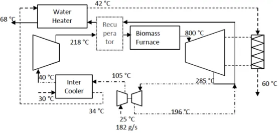
As shown later, the main originality of the proposed EHE is to be based on an existing Internal Combustion Engine (ICE), which allows the development effort and production cost to be reduced. The envisioned system is represented in Fig. 1. An EHE operates according to an open Joule/Brayton cycle. Air is compressed in a compressor, heated in a furnace and expanded in an expander. The net produced mechanical power is the difference between the expander and the compressor powers. In order to improve the performance of the system, a turbocompressor (and its intercooler) and a recuperator can be used. In CHP applications, heat can be recovered from the engine jacket cooling circuit, from the exhaust gases and from the intercooler in order to produce hot water. Fig.1 features the targeted temperature on both the air-side and water-side.
Fig. 1. Schematic representation of the Ericsson heat engine-based CHP unit
The paper is organized as follows. In the first section, two different modeling approaches of piston machines (a detailed model and a semi-empirical model) will be briefly described. In the second section the development of a prototype of EHE will be presented. This development makes use of the detailed model of the piston machines. The experimental characterization of the prototype will be detailed in the third section. Experimental data will also be used to calibrate the simulation models and to understand the gap between forecasted performance and actual measured performance. Using the semi-empirical piston expander model, the last section of the paper will present the performance of the overall CHP unit based on a few realistic assumptions regarding the improvement of the current EHE prototype.
2. Modelling of piston machines
2.1. Detailed piston compressor and expander models
The detailed piston expander is based on a combination of a geometrical model and a thermodynamic model. The geometrical model computes the crank angle evolution of the control volume delimited by the cylinder wall and piston and of the supply and discharge port cross sectional areas. The thermodynamic model computes the evolution of the fluid state inside the control volume by expressing and numerically solving the differential equations of conservation of mass and energy (1) and (2).
!" !" = 𝑚!"− 𝑚!" (1) !" !" = ! !.!!. −𝑇. !" !" !. !" !"− 𝑣. !" !" + ! !+ !!" ! . (ℎ!"− ℎ) (2)
The thermodynamic model accounts for heat transfer between the fluid and the metal wall as well as pressure drops encountered by the fluid when flowing through the supply and exhaust ports. These pressure drops are computed by representing supply and exhaust flows as isentropic flows through simply converging nozzles. Two assumptions are made: the fluid thermodynamic state inside the cylinder and the wall temperature are both uniform. The convective heat transfer coefficient between the air and the cylinder wall is evaluated by the Annand correlation [1]. Internal leakages are not described, since it was assumed that their impact is limited.
The input variables of the model are the air supply and discharge pressures, the supply temperature and the rotational speed. The output variables are the displaced mass flow rate, the consumed/produced power and the air exhaust temperature. The air mass flow rate displaced by the piston compressor and expander is defined as the average, over one shaft revolution, of the mass flow rate entering/leaving the machines. The average enthalpies at the outlet of the compressor and expander are computed by (3). Knowing the average exhaust enthalpy, the exhaust temperature can be determined. ℎ!" = !!!!!!.!!!" ! .!!"! .!" !!"! .!" !!!.! !!! (3)
Detailed compressor and expander models allow indicators diagrams to be drawn. Such diagrams are presented in Fig. 2. Diagrams accounting for pressure drops (DP), heat transfer (HT) and anticipated opening of exhaust valve (AEVO) are compared to the diagrams without losses (WL). More information about the models can be found in a previous publication by the authors [2].
Fig. 2. Indicator diagrams of the piston compressor and expander predicted by the detailed model
2.2. Semi-empirical model
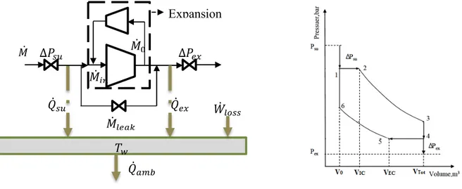
The semi-empirical model is based on a lumped parameter approach [3]. The fluid is assumed to encounter different consecutive steps (Fig. 3 (left)): supply and exhaust pressure drops, heat transfer with the machine metal mass during suction and discharge, internal expansion and mixing between internal flow and leakage flow. The model also accounts for the heat transfer with the ambient and the mechanical losses. The internal expansion is described by the theoretical indicator diagram of Fig. 3 (right). This diagram only accounts for under- and over-expansion and compression losses. Input and output variables are the same as those of the detailed model.
Fig. 3. Schematic representation of the piston expander semi-empirical model (left) and theoretical indicator diagram considered to describe the fluid internal expansion (right)
3. Development of the EHE prototype
The EHE prototype to be developed is assumed to work with a compressor supply temperature of 25°C and an expander supply temperature of 800°C. This temperature is limited by material constraints.
3.1. Preliminary design
The purpose of the preliminary design, more extensively described in [2], was to determine the required swept volumes of the piston compressor and expander based on the targeted operating conditions. The detailed compressor and expander models are coupled. The heat exchanger effectiveness is imposed to 80%. Since the same mass flow rate travels both the expander and the compressor, the expander supply pressure becomes an output of the overall model once the swept volumes of both compressor and expander are fixed. The engine volume ratio is defined as the ratio between the expander and compressor swept volumes (4).
𝛷 =!!
!! (4)
For a temperature ratio (ratio between the expander and compressor supply temperatures), the pressure ratio (ratio between the expander and compressor supply pressures) is thus imposed by the volume ratio. Fig. 4 shows the evolution of the volume ratio with the desired pressure ratio for two versions of the detailed model of the piston machines: without any losses (WL) and with pressure drops (PD) and heat transfers (HT).
Expansion process 𝑄̇!" Δ𝑃!" Δ𝑃!" 𝑄̇!" 𝑀̇!"#$ 𝑀̇! 𝑀̇!" 𝑀̇ 𝑇! 𝑄̇!"# 𝑊̇!"##
Fig. 4. Evolution of the volume ratio with the pressure ratio
Fig. 5. Evolution of the EHE thermal efficiency with the pressure ratio
Fig. 5 shows the evolution of the thermal efficiency of the EHE with the pressure ratio for different versions of the detailed model. Also, the use of a recuperator (Reg) and an anticipation of the compressor exhaust valve opening (AEVO) of 10° is investigated. Such a modification of the exhaust valve timing allows for a reduction of the exhaust pressure drop, which slightly increases the EHE thermal efficiency. As it is well known, using a recuperator yields a lower optimal pressure ratio and a higher cycle efficiency. Fig. 5 also illustrates the large impact of losses inside the compressor and expander on the engine efficiency. As indicated in Fig. 5, the optimal pressure ratio is 4.4, which corresponds according to Fig. 4 to a volume ratio of 2.2.
Simulation indicated that heat losses have to be taken into consideration. Actually, they yield a larger mass flow rate admitted by the expander because of the cooling down of the air and a lower mass flow rate admitted by compressor due to the air heating up. Consequently, for the same volume ratio, a lower pressure ratio is achieved. Moreover, the air temperature at the exhaust of the expander and thus at the supply of the recuperator is lower, limiting the positive effect of the recuperator.
3.2. Construction of the prototype
Based on this preliminary design, a prototype has been built by adapting a 12-litter, 6-cylinder in line natural gas ICE. This engine, originally designed for CHP application, shows a nominal power of 75 kW and nominal rotational speed of 1500 rpm. The cylinders bore, stroke and clearance factor are 130 mm, 150 mm and 9%, respectively. Since only an integer value of the volume ratio can be achieved, a value of 2 has been considered, which corresponds to the use of 2 cylinders in compressor mode and 4 cylinders in expander mode.
With respect to the original engine design, the following major modifications have been implemented:
- The Ericsson engine is a 2-stroke engine, while the original ICE is a 4-stroke one. Also pressure forces acting on valves are different. This required a modification of the valve train. - Four manifolds (compressor supply and exhaust and expander supply and exhaust) had to be
built instead of two in the original ICE (Fig. 6 left).
- The original bowl-in pistons had to be replaced by flat piston with valves relieves in order to decrease the clearance volume (1.6% vs 9%) (Fig. 6 right).
Fig. 6. Left: View of the EHE manifolds. Right: View of original and new piston
The EHE has been coupled to an induction motor connected to the electricity grid through a 4-quadrant variable-frequency drive (VFD). The induction machine can work either in motor mode or in generator mode.
4. Experimental investigation
4.1. Description of the test bench
The EHE has been coupled to an electrical air heater that mimics the biomass boiler. This heater is used to heat the air between the compressor stage outlet and the expander stage inlet. The engine is cooled down by water. As shown in Fig. 7, the engine primary water cooling loop transfers heat to a secondary cooling loop through a plate heat exchanger. The secondary loop is connected to a dry-cooler.
Fig. 7. Schematic representation of the EHE test bench
Air and water pressures and temperatures are measured at the major locations of the system. Piezoresistive pressure sensors, PT100 temperature sensors and K-type thermocouples (for high temperature measurements) are used. A hot wire mass flow rate, measures the air mass flow rate as the compressor supply. As explained hereunder, after the first campaign, a commercial compressor
had to be used to provide additional air flow through the expander. Mass flow rate added by the additional compressor is determined by measuring the total mass flow rate at the exhaust of the expander by means of an orifice plate and a differential pressure sensor. The VFD provides a measurement of the generated or consumed electrical power and of the engine rotational speed. Additionally, piezoelectric pressure sensors equip some of the cylinders and a rotary encoder allows for the measurement of the angular position of the crankshaft. These measurements are combined together to derive the indicator diagrams.
4.2. Analysis of the measurements
A first campaign of measurements has been carried out without the additional compressor. It was not possible to achieve neither the targeted expander supply pressure of 5 bar nor the expander supply temperature of 800°C. The maximal achieved temperature was 360°C, which can be explained by a malfunction of the electrical boiler. With these operating limits, the EHE was not able to produce a positive net power and the induction machine worked as a motor to run the EHE. For the second campaign of tests, based on indicator diagram analysis, the camshaft has been modified to obtain longer compressor valve opening during suction and discharge times and a higher maximal valve lift. For the expander, the valve opening duration has also been increased and the exhaust valve closing angle has been modified to prevent over-compression at the end of the compression phase. Also, an additional compressor has been used to inject air before the electrical heater. This allowed the pressure at the expander supply to be increased up to 7 bar. In total, 54 experimental points have been achieved with a rotational speed ranging from 300 to 900 rpm and an expander supply temperature ranging from 420°C to 480°C. Even if the engine is not conceived to work with an additional compressor, the use of the latter allowed characterizing the expander part of the engine and helping understanding why it has not operated as expected during the design phase. By measuring the indicated powers of both the compressor cylinders and expander cylinders, the net indicated power transmitted to the shaft can be computed. Based on the performance curve of the induction motor and on the measurement of the electric power, the EHE shaft power can be computed. Knowing the mechanical power and the indicator power, the friction power of the 6-cylinder engine can be determined. Considering, a 12 l displacement, the correlation (5) can be deduced for the friction mean effective pressure fmep.
𝑓𝑚𝑒𝑝 [𝑏𝑎𝑟] = 0.205 + 0.00016. 𝑅𝑃𝑀 (5)
The mechanical losses associated to the 4-piston expander stage are estimated by assuming that they represent 4/6 of the global engine mechanical losses. Knowing the mechanical efficiency of the expander, the shaft isentropic effectiveness can be estimated. It is defined as the ratio of the shaft power and the isentropic power, which is the product of the mass flow rate entering the expander and the variation of specific enthalpy associated with an isentropic expansion (Eq. (6)).
𝜖!,!! =! !!!!
!"!!!",! (6)
The evolution of the shaft isentropic effectiveness with the pressure ratio is presented in Fig. 8. This figure also features the evolution of the theoretical isentropic effectiveness and internal isentropic effectiveness. The former only accounts for under- and over- compression and expansion losses. The latter is defined as the ratio between the indicated power and the isentropic power. These performance indicators are defined in [4].
Fig. 8 indicates that the maximum shaft isentropic effectiveness is 61% and makes appear an optimal rotational speed of 600 rpm.
Fig. 8. Evolution, with the pressure ratio, of the theoretical isentropic effectiveness, of the internal isentropic effectiveness and of the shaft isentropic effectiveness
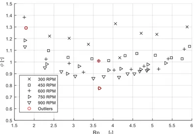
The evolution of the filling factor with the pressure ratio, for different rotational speeds, is given in Fig. 9. The filling factor is defined as the ratio between the mass flow rate entering the machine and the theoretical mass flow rate that should enter, based on the displacement and rotational speed of the expander. Larger filling factors are obtained at lower speeds, because of the most important impact of internal leakages.
Fig. 9. Evolution, with the pressure ratio, of the filling factor
In-cylinder pressure sensors allowed for the measurement of the indicator diagrams associated with some of the expander cylinders. Such a diagram is shown in Fig. 10 for a given cylinder and rotational speed and several supply pressures. Pressure drops during suction are visible. The first pressure drop can be explained by the fact that the cylinder volume increases while the valve opening is still limited. Similarly, the pre-expansion is due to the decreasing supply-port cross section area while the volume is keeping on increasing.
Fig. 10. Measured indicator diagram of one of the cylinders for a rotational speed of 600 rpm
4.3. Calibration of the expander simulation models
The measurements presented in the last section have been used to calibrate simulation models presented in section 2.
4.3.1. Expander detailed model
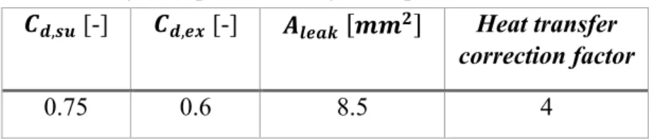
In order to better predict the pressure drops, discharge coefficients of 0.75 and 0.6 have been applied to the supply and exhaust ports respectively. Also, to better predict the discharge temperature, a correction factor has been introduced in the Annand correlation for the heat transfer.
Table 1. Adjusted parameters of the expander detailed model
𝑪𝒅,𝒔𝒖 [-] 𝑪𝒅,𝒆𝒙 [-] 𝑨𝒍𝒆𝒂𝒌 𝒎𝒎𝟐 Heat transfer
correction factor
0.75 0.6 8.5 4
Comparison between the predicted and measured indicator diagrams is shown in Fig. 11 for a rotational speed of 600 rpm and 3 levels of supply pressure: 1.8, 4 and 6 bar.
To better predict the mass flow rate, a lumped leakage flow rate between the expander supply and exhaust has been introduced in the model. The best agreement between the measurements and the model prediction, illustrated in Fig. 12, is found with a lumped leakage area of 8.5 mm2.
Fig. 11. Comparison between measured and predicted indicator diagrams of one of the cylinders for a rotational speed of 600 rpm
Fig. 12. Prediction by the expander detailed model of the mass flow rate displaced by the expander
Using the calibrated model, Fig. 13 provides a comparison between the forecasted EHE performance (considering the design presented in section 3) and the actual performance and explains the underlying reasons for the performance gap. First, the second design of camshaft increased the cut-off length of the stroke and hence decreased the expander supply pressure and pressure ratio. This yielded a decrease of the EHE efficiency. Operation at 450°C rather than 800°C at the expander supply sharply cut off the performance. Finally, internal leakages have a major negative impact on the EHE performance. With the actual design, even if a temperature of 800°C would be achieved at the expander supply, only a 1% efficiency would be reached.
Fig. 13. Comparison between forecasted EHE performance and actual performance
4.3.2. Expander semi-empirical model
In order to calibrate the expander semi-empirical models, the parameters given in Table 2 have been adjusted (supply and exhaust ports cross sectional areas, leakage area, supply and exhaust heat transfer coefficients).
Table 2. Adjusted parameters of the expander semi-empirical model
𝑨𝒔𝒖 [𝒎𝒎𝟐] 𝑨
𝒆𝒙 [𝒎𝒎²] 𝑨𝒍𝒆𝒂𝒌 𝒎𝒎𝟐 𝑨𝑼𝒔𝒖 [𝑾/𝑲] 𝑨𝑼𝒆𝒙 [𝑾/𝑲]
63 314 8 10 40
Fig. 14 indicates that a rather good agreement between the predictions by the model and the measurements is achieved.
Fig. 14 Prediction by the expander detailed model of the indicated work (left) and displaced mass flow rate (right)
5. Performance of the CHP unit
In this section, the performance of an Ericsson engine-based CHP unit is investigated by using the semi-empirical model of the piston expander presented and calibrated in previous sections. Previous experimental investigation has shown that the compressor stage from the ICE shows large leakages. Also the valve timing is defined for one single compression ratio, which yields poor efficiency
outside the nominal point. Hence, it has been decided to use a commercial compressor with a better efficiency. An isentropic efficiency of 80% is assumed. For the expander, the same ICE is considered but with the whole six cylinders operating in expander mode. Also, the engine is equipped with a turbo-compressor, with a compressor efficiency of 80% and a turbine efficiency of 70%. The compressor supply pressure is assumed to be 2 bar.
The performance achieved for different design variations are shown in Fig. 15 in terms of EHE efficiency and net power as function of the compressor pressure ratio. It should be mentioned that when using a turbo-compressor, the pressure ratio is not the same on compressor and expander stages. The use of a turbo-compressor allows for a 1% point efficiency increase. When using the turbo-compressor, the gas temperature at the supply of the recuperator is lowered. Consequently, in some cases, the recuperator introduces a penalty. Fig. 15 indicates that a thermal efficiency of the EHE of 8% could be achieved with realistic modifications of the engine design (reduction of cut-off (CO), leakages divided by 2 and pulsation attenuation).
Fig. 15. Turbo-compressed Ericsson Heat Engine efficiency and net power as a function of the pressure ratio on the compressor
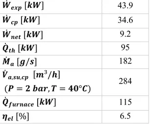
The overall performance of the CHP unit are estimated based on the following assumptions: 100% of the intercooler cooling power is recovered, 95% of the thermal power of the engine cooling loop is recovered and the heat exchanger on the exhaust gases has a 80% effectiveness. In the operating conditions shown in Fig. 1, a global thermal power of 89 kW is recovered. Assuming a generator efficiency of 95%, a biomass boiler efficiency of 86% and an EHE efficiency of 8% (according to Fig. 15), a CHP electrical efficiency of 6.5% an a thermal efficiency of 70.5% are achieved, leading to a primary energy saving (PES) of 2%.
Table 3. Performance of the Turbo-compressed Ericsson Heat Engine
𝑾𝒆𝒙𝒑 [𝒌𝑾] 43.9 𝑾𝒄𝒑 [𝒌𝑾] 34.6 𝑾𝒏𝒆𝒕 [𝒌𝑾] 9.2 𝑸𝒕𝒉 [𝒌𝑾] 95 𝑴𝒂 [𝒈/𝒔] 182 𝑽𝒂,𝒔𝒖,𝒄𝒑 𝒎³/𝒉 (𝑷 = 𝟐 𝒃𝒂𝒓, 𝑻 = 𝟒𝟎°𝑪) 284 𝑸𝒇𝒖𝒓𝒏𝒂𝒄𝒆 [𝒌𝑾] 115 𝜼𝒆𝒍 [%] 6.5
𝜼𝒕𝒉 [%] 70.5
𝑷𝑬𝑺 [%] 2
6. Conclusions
In this work, it was proposed to modify an existing internal combustion engine in order to build an Ericsson Heat Engine used for solid biomass CHP. The pre-design based on detailed simulation models of the piston compressor and expander has been presented. Modifications of the original ICE have been listed. The prototype of EHE has not worked as expected. This is mainly due to malfunction of the electric heater and to too large internal leakages inside the EHE. In order to increase the expander supply pressure, an external air compressor has been used. This allowed for a better characterization of the piston expander, which highlighted the impact of valve timing, leakage, mechanical friction and pressure drops.
Even if the actual prototype has not produced a positive net power, simulation has been conducted to investigate the impact of design improvements. By using a commercial compressor, the whole 6 cylinders as expanders, a turbo-compressor and improving the design of the expander (of which current maximal shaft isentropic effectiveness is 61%), an overall electrical efficiency of 6.5% and a thermal efficiency of 70.5% could be achieved.
Acknowledgments
The results presented in this paper have been obtained within the frame of the Comotex project funded by the Walloon Region of Belgium. This financial support is gratefully acknowledged.
Nomenclature
c specific heat, J/(kg K)
h heat transfer coefficient, W/(m2 K)
h specific enthalpy, W/(m2 K) 𝑃 Pressure, bar or Pa 𝑄 thermal power, W 𝑊 power, W T temperature, °C Greek symbols 𝜖 effectiveness 𝜂 efficiency 𝛷 filling factor
Subscripts and superscripts
a Air cp Compressor e Electrical ex Exhaust exp Expander s Isentropic sh Shaft su Supply
References
[1] Annand W.J.D., Heat Transfer in the Cylinders of Reciprocating Internal Combustion Engines. In Proc. Instn Mech. Engrs 1963; 117:973–90.
[2] Oudkerk J.F., Lemort V., Theorical study of a volumetric hot air Joule cycle engine. Proceedings of the 3rd International Conference on Microgeneration and Related Technologies – Microgen III, Napoli, April 15-17, 2013.
[3] Oudkerk J.F., Dickes R., Dumont O., Lemort V., Experimental performance of a piston expander in a small-scale organic Rankine cycle. IOP Conf. Series: Materials Science and Engineering 2015; 90 012066
[4] Lemort V., Legros A., Positive displacement expanders for Organic Rankine Cycle systems. In book: Organic Rankine Cycle (ORC) Power Systems: Technologies and Applications, Edition: 1st. Publisher: Elsevier, WoodHead publishing series in Energy. Editors: E. Macchi and M. Astolfi, 2016