HAL Id: hal-00483663
https://hal.archives-ouvertes.fr/hal-00483663
Submitted on 15 May 2010
HAL is a multi-disciplinary open access
archive for the deposit and dissemination of sci-entific research documents, whether they are pub-lished or not. The documents may come from teaching and research institutions in France or abroad, or from public or private research centers.
L’archive ouverte pluridisciplinaire HAL, est destinée au dépôt et à la diffusion de documents scientifiques de niveau recherche, publiés ou non, émanant des établissements d’enseignement et de recherche français ou étrangers, des laboratoires publics ou privés.
Four Reasoning Models for C3 Metamodel
Abdelkrim Amirat, Mourad Oussalah
To cite this version:
Abdelkrim Amirat, Mourad Oussalah. Four Reasoning Models for C3 Metamodel. International Review on Computers and Software (IRECOS), Praise Worthy Prize, 2007, 2 (6), pp.594-601. �hal-00483663�
Copyright © 2007 Praise Worthy Prize S.r.l. - All rights reserved International Review on Computers and Software, Vol. xx, n. x
Four Reasoning Models for C3 Metamodel
Abdelkrim Amirat and Mourad Oussalah
Abstract - The architecture is considered to be the driving aspect of the development process; it allows specifying which aspects and models in each level needed according to the software architecture design. Early Architecture Description Languages (ADLs), nearly exclusive, focus on structural abstraction hierarchy ignoring behavioural description hierarchy, conceptual hierarchy, and metamodeling hierarchy. In our approach these four hierarchies constitute views to appropriately “reason about” the architecture of a system described using our C3 metamodel. C3 is defined to be a minimal and complete architecture description language. In this paper we provide a set of mechanisms to deal with different levels of each type of hierarchy, also we introduce our proper structural definition for connector types used to instantiate any connexion elements deployed at the architectures and application levels.
Keywords: Conceptual, Configuration, Connector, Behaviour, Hierarchy, Metamodeling,
Structure
I.
Introduction
One of the key goals of software architecture research is to understand and to manipulate a system at a higher level of granularity than modules or lines of code. Generally, software architectures are composed of components, connectors and configurations, constraints on the arrangement and behaviour of components and connectors. The architecture of a software system is a model, or abstraction of that system. Software architecture researchers need extensible, flexible architecture descriptions languages (ADLs) and equally clear and flexible mechanisms to manipulate these core elements of the architecture.
Recently Medvidovic [1] gives the following definition for software architecture “A software system’s architecture is the set of design decisions about the system which, if made incorrectly, may cause your project to be cancelled”. However, these design decisions encompass every aspect of the system under development, including:
• Design decisions related to system structure – for
example, “there should be exactly three components in the system, the data store, the business logic and the user interface component;”
• Design decisions related to behaviour (also referred to
as functional) – for example, “data processing, storage, and visualisation will be handled separately;”
• Design decisions related to the system’s non
functional properties – for example, “the system dependability will be ensured by replicated processing modules;”
• Also, we can elicit other design decisions related to
the development process or the business position (product-line).
We note that in the description languages architectures (ADLs) that currently exist, there is no standard about architectural concepts or standards in terms of mechanisms for manipulating those concepts (i.g. in the ADLs defining explicit connectors, we see that each one gives its proper definition for connectors, some ADLs define the concept of configuration while others do not).
For the reasoning model, the majority of ADLs proposes only sub-typing (inheritance) as a mechanism for specialization (e.g. Acme, C2). Otherwise, for the rest of ADLs, they propose their own ad hoc mechanisms based on methods designed specially for these ADLs.
Based on a bread survey of architecture description notations and approaches, we identified that ADLs capture aspects of software design centred around a system’s Component, connectors, and configurations. The core elements of our model are basically defined around these tree elements. So, from this we derive the name of our model C3 for Component, Connector, and Configuration. Taking into consideration that our C3
have no relationship with C2 defined bay Taylor [2] nor with C3 with is an extension of C2 defined by Pérez-Martínez [3]. The rest of the paper is organized as fellows. In section 2 presents our research motivations. Section 3 describes the C3 metamodel C3. The last section presents our conclusion and the different perspectives of our work.
A. Amirat, M. Oussalah
Copyright © 2007 Praise Worthy Prize S.r.l. - All rights reserved International Review on Computers and Software, Vol. xx, n. x
II. Motivation
In this work the goal is to develop a generic model for the description of software architectures which must be minimal and complete. It is minimal because we are only interested by the core concepts in each ADL. And complete because with this minimum of concepts the architect can be able to describe any required structures he need to realize.
However, describing only the architecture structure is not sufficient to provide correct and reliable software systems. In this paper we are even more going to focus on representation architecture model and to raison about its elements following four different types of hierarchies. Each of these hierarchies provides a particular view on the architecture. In the following sections we present more details about these hierarchies. Using our approach software architecture is more explicit and clarified by:
• Make explicit the possible types of hierarchies being
used as support of reasoning on the architectures, with the different possible levels in each hierarchy.
• Show semantics convey by every type of hierarchy by
providing the necessary mechanisms used to connect elements of in the same level of hierarchy and the mechanisms used to connect elements of every level with the elements of the super and lower levels.
• Allows introducing various mechanisms of reasoning
within the same architecture according to the requirement problem in a specific domain space.
• Establish the position of existing mechanisms
developed for reasoning with regard to our referential. In order to have a complete C3 model, we define mainly two models to describe and raison about software architectures. A representation model to describe any architecture based on C3 elements and a reasoning model to understand and analyse the representation model.
III. Representation Model
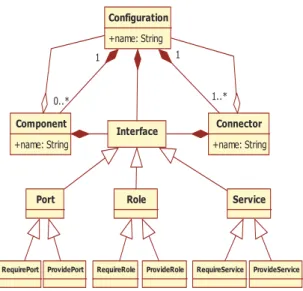
The core elements of the C3 representation model are components, connectors, and configurations, each of these elements have an interface to interact with its environment. Figure 1 depicts those principal elements.
III.1. Component
Components represent computation elements and data storage for software systems. In C3, each component can have one or more ports. Ports are the interaction points between components and their environments.
Fig. 1. Basic elements of C3 Meta model
III.2. Connector
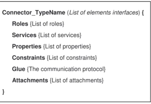
Connectors are very important entities that unfortunately are not dealt with by the conventional component-based models. In C3, connectors represents interconnections among components for supporting their interactions and they are defined explicitly and considered as a first class entities by separating their interfaces (roles) from their services [4]. The glue represents the mapping function between the input roles and the output roles. Our contribution at this level consists in enhancing the structure connectors by encapsulating the attachment links inside the connector (Figure 2.a). So, the application builder will have to spend no effort in connecting connectors with its compatible components/configuration. Consequently, the task of the developer consists only in choosing a suitable type of connector which is compatible with the types of components/configurations which are expected to be connected. Thus, by this way the application will be constructed like a Lego blocks where the attachments are predefined inside each type of connector. We have given the following definition (Figure 2.b) for connectors in a previous work [5].
Fig. 1.a. The new structure of a connector
Glue Component B Component A P1 P2 R2 R1 P4 P5 R4 R3
Attachment New structure of a connector
Old structure of a connector
Copyright © 2007 Praise Worthy Prize S.r.l. - All rights reserved International Review on Computers and Software, Vol. xx, n. x
Fig. 1.b. Syntax of a connector
III.3. Configuration
For more clarity, in our model C3 each component or connector is perceived and handled from the outside as primitive element. But their inside can be real primitive elements, or composite with a configuration which wrap up all the internal elements of this composite. These configurations are first class entities. They represent a graph of components and connectors and describe how they are fastened to each other. A configuration may have ports, and each port is bound to one or more ports of the internal components. In general, configurations can be hierarchical where components and connectors represent sub-configurations that have internal architectures as represented in Figure 1.
III.4. Interface
Every architectural element has an interface. Each interface is associated with a type which corresponds to a set of operations which it defines. Via this interface the element publish to the outside environment it needs in term of required services as well as the services which it provides. However, elements are selected and connected from their published interface. So, the interface is though as a contract with the environment that the element should honour.
To establish connections between elements we use ports for components and configurations and roles for connectors and we assign the services to each port and role with a necessary set of constraints to be respected during the connections. From conceptual view ports and roles are concrete classes inherited from the interface abstract class as shown in Figure 2.
Also, in modelling level we use cardinality to describe the multiplicity of each relation (connection) between architectural elements. This cardinality express the number of ports associated with components and configurations and the number of roles associated with connectors. Each port or role is considered as a channel to carry in/out required/provided services exchanged with element environment.
The previous architectural elements are manipulated and used via predefined mechanisms in the reasoning model. Essentially, we are going to study the instantiation, specialization, composition, decomposition, and connections mechanisms. In the following section, we define the using context of each mechanism. Some details about the structure of these architectural elements are presented in our previous works [5]-[6]
IV. Reasoning Model
In our approach we intended to analyze the software architecture by using different hierarchies where each hierarchy is investigated at different levels of representations. The Figure 3 illustrates the C3 reasoning model of C3. This model is defined by four types of hierarchies and each type represents a specific view on the C3 representation model different from the others. The four hierarchies are:
Fig. 3. C3 Meta Model and reasoning models
The structural abstraction hierarchy used to explicit the different nested levels of structural hierarchies that software architecture can have.
The behavioural description hierarchy to explicit the different levels of system behaviour hierarchy represented bay protocols.
The conceptual hierarchy to describe the library of element types corresponding to each element at the architecture level.
The metamodeling hierarchy to locate our C3 model in the pyramid of hierarchies defined by the OMG [5].
We associate to each hierarchy two points of views. The first one is an external view “the logical architecture” as it is perceived by the user (designer or developer) of the architecture. The second kind of view is internal view “the physical architecture” which Connector_TypeName (List of elements interfaces) {
Roles {List of roles} Services {List of services} Properties {List of properties} Constraints {List of constraints} Glue {The communication protocol}
Attachments {List of attachments}
} Behavioural Hierarchy -II- -III- Conceptual Hierarchy -IV- Metamodeling Hierarchy Structural Hierarchy -I- C3 Representation Metamodel
A. Amirat, M. Oussalah
Copyright © 2007 Praise Worthy Prize S.r.l. - All rights reserved International Review on Computers and Software, Vol. xx, n. x represents the memory image of the logical architecture.
Some details about the logical and physical architecture are presented in [6]. In the following sections, we present those types of hierarchy and we investigate the possible levels of each hierarchy.
IV.1. Structural Hierarchy (SH)
Structural hierarchy also called structural hierarchy has to provide the structure of a particular architecture in terms of the architectural elements defined by the ADL. The majority of academic ADLs like Aesop, MetaH, Rapide, SADL, and other [7] or the industrials like CORBA, CCM/CORBA, EJB/J2EE [8] allow only a flat description of software architectures.
Using those ADLs architecture is described only in terms of components connected by connectors without any nested elements - without any structural hierarchy. This design choice was made in order to simplify the structure and also by lack of concepts and mechanisms that respectively define and manipulate configurations of components and connectors.
In our C3 model the structure of architectures is described using components, and connectors, and configurations where configurations are composite elements. Each element in this configuration (component or connector) can be a primitive (with a basic behaviour scenario) or configuration which contains another set of components and connectors, which in their turn can be primitive or composite material, and so on.
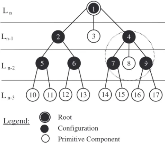
However, the metamodel C3 allows the representation of architecture with a real hierarchy (with an arbitrary n abstraction levels). It should be noted that practically all architectural solutions for domain problems, have a nested hierarchical nature. Thus, software architecture can be viewed as a graph where each internal node of this graph represents a configuration and each end-node represents a primitive component arcs between nodes are connectors.
In Figure 4.a, the root node is the first level of abstraction; it is also the configuration which encapsulates all elements of the architecture. The small white circles represent primitive components and small black circles represent sub-configurations (composites) in the system architecture. These configurations contain other elements inside. Thus, the configurations will never be end-nodes in the hierarchy tree of abstractions. The node with double circles represents the global configuration of the architecture. The arcs represent the bonds of hierarchy - the father/child relationship. This relationship does not necessarily imply a service-connection between the father node and the child one. To explicit the parental relationship between each element and its sub-elements we define the following type of connector:
Fig. 4.a. External view of the structural hierarchy
• Composition-Decomposition Structural Connector
(CDSC) used to link each configuration to its underling elements. Therefore, this type of connector allows the navigation among levels of the structural hierarchy. Also, we can determine the childs or the father, if it is the case, of each elements deployed in the architecture. Figure 4.b represents the notation adopted for this type of connectors.
Fig. 4.b. CDSA connector
Figures 5.a illustrates two service-connection types of connector; the fist one is generally represented by an implicit link called Binding and the second one is defined by several ADLs as Attachment link. In our model those two types of link are explicated as first class entities and are defined as follows:
Fig. 5.a. Internal view of the structural hierarchy Root Configuration Primitive Component Legend: 2 3 4 7 8 9 14 5 6 15 17 13 16 10 11 12 1 L n L n-3 L n-2 Ln-1
Attachment Connector (Assembly) Expansion-Compression Connector Legend: CDCA C om po si tio n Dec om po sit io n 4 7 8 9 2 3 4 7 8 9 14 5 6 15 17 13 16 10 11 12 1 e1 e1.1 e1.2 s2 s4 s3 s1 s9 s16 s17
Copyright © 2007 Praise Worthy Prize S.r.l. - All rights reserved International Review on Computers and Software, Vol. xx, n. x • Expansion-Compression Connector (ECC) is
represented by discontinuous arc. We use this type of connectors to establish service-connections between each configuration and the underling elements (Figure 5.b). In some ADLs this type of link is called binding or delegation but not defined as a first class entity.
Fig. 5.b. ECC connector
• Structural Attachment Connector (SAC) is
represented by full arc. We use this type of connectors to establish service-connections between components and configurations deployed in the same level of abstraction (Figure 5.c). In some ADLs this type of connector in called assembling connector and represented by first class entity (e.g. Acme) [9].
Inside the SAC connector the glue code (Figure 5.c) defines the mapping among communicating elements.
• The provided service of “a” is required by “x” (e1=s1),
• The provided service of “b” is required by “z” (e2=s2),
• The provided service of “c” is required by “y” (e3=s3).
Attachments among elements {a,b,c,x,y,z} and the SAC connector are also defined inside the connector. We note that the example described in Figure 5.c is independent from the one described in Figure 5.a.
The different elements of the architecture are connected through their interfaces. Thus the types of interfaces are checked if they are compatible or not (interface matching). Consequently, in the structural hierarchy, the consistency of elements assembly is controlled syntactically.
Fig. 5.c. Internal view of SAC connector
IV.2. Behavioural hierarchy (BH)
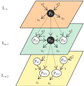
The behavioural description hierarchy represent the description of the system’s behaviour at different levels. Each primitive element of the architecture has its own behaviour. The behaviour description associated with the highest level of the hierarchy - level n in Figure 6.a - represents the overall behaviour of the architecture. This behaviour is described by a global protocol P0. The system architecture at this level is perceived as a black box with inputs (required services) and outputs (provided services). At lower level each component, connector, configuration, port, or role has its own protocol to describe its functionality (e.g. glue code is the protocol describing the connector behaviour, also the component behaviour can be described by a state chart diagram). So, protocol is a mechanism used specifying the behaviour of an architectural element by defining the relationship among the possible states of this element and its ability to produce coherent results.
Figure 6.a sketches by a plan representation how to decompose the protocol P0 at level n into its sub-protocols at level n-1. This decomposition process produces a set of other behaviours {P01, P02, P03}. By the same process each protocol of the level n-1 is decomposed to produce an other set of sub-protocols at the level n-2, and so on until level 0. The last level of the hierarchy is a set of protocols representing primitive behaviour elements which are available in the library of the architect. The total set of protocol levels represents the behaviour hierarchy of the system architecture.
So, by Figure 6.a we explicit that all inputs and outputs are preserved at each plane representation.
Fig. 6.a. Plane representation of behavioural hierarchy
P0 P01 P03 P02 P032 P031 e1 e2 e1 e2 x y P01 P02 s2 s1 e1 e2 s2 s1 s2 s1 x y
Legend: Pi: Protocol (i); ej : Input (j) ; sk: Output (k);
x , y : intermediate results L n L n-2 Ln-1 ECC e1 e1.2 e1.1 1 2 4 ECC s9 s16 9 E xp an si on C om pre ssi on 16 17 s16 e1 s9 SAC a y x z b e2 c e1 e3 s2 s3 s1
A. Amirat, M. Oussalah
Copyright © 2007 Praise Worthy Prize S.r.l. - All rights reserved International Review on Computers and Software, Vol. xx, n. x • Composition-Decomposition Behavioural Connector
(CDBC) used to link each protocol to its possible sub-protocols. Therefore, this type of connector allows the navigation among levels of the behavioural description hierarchy. Also, we can determine the childs or the father, if it is the case, of each protocol used in the architecture. Figure 6.b represents the notation adopted to represent this type of connector.
Fig. 6.b. CDCB connector
To navigate among behavioural description hierarchy levels we define the following type of connector:
• Binding Identity Connector (BIC) used to keep the
identity and the traceability of inputs and outputs of protocols. There is no expansion or compression of respectively inputs and outputs of protocols like in structural hierarchy. The identity of inputs and output is preserved (Figure 6.c).
• Behaviour Attachment connector (BAC) used to
connect protocols belonging to the same level of hierarchy. This connection is explicated by real transition between the end-state of the first protocol and the start-state of the second one (Figure 6.c)
Fig. 6.c. BIC and BAC connectors
If we use, for example, transition-based system to specify the behaviour protocol associated with each element then connections between behaviours are made by simple transitions between the end-state of the fist protocol and the start-state of the second one. Inputs and outputs of each protocol are respectively required and provided services.
The syntactic correction (discussed before) of the assembled elements cannot insure the validation of the produced architecture. The syntactic correction checks only the compatibility of interfaces types. So, elements are compatible to exchange information, but fail to check if their collaboration “the semantic of connections” can produce a coherent result. Consequently, the behavioural description can insure the compatibility of protocols (protocol matching) associated with elements at any level of the hierarchy [10].
IV.3. Conceptual hierarchy (CH)
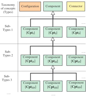
The conceptual hierarchy allow the architect to model the relationship among elements of the same family as illustrated in Figure 7.a. The architectural entities are represented by types (classes). Each type is a class library and each class have its sub-classes in the library. So, we can shape the graph representing entities hierarchy of the same family. Each graph has its proper number of levels (sub-type levels).
At the highest level of hierarchy we have the basic element types developed to be reused. The element types of the intermediate levels are created by reusing the previous ones. Those intermediate element types are reused to produce others (development by reuse and to be reused) or used as end-elements to describe architectures, and so on. Element types at the last level of the hierarchy are only created to be used in the description of architectures.
Fig. 7.a. External view of the conceptual hierarchy
CDCB C om po si tio n Dec om po sit io n P0 P01 P03 P02 Component Component [Cpt2] Component [Cpt1] Component [Cpt3] Component [Cpt22] Connector Component [Cpt221] Component [Cpt222] Component [Cpt223] Taxonomy of concepts (Types) Sub- Types 1 Sub- Types 2 Component [Cpt23] Component [Cpt21] Sub- Types 3 Configuration …. …. …. …. …. BIC e1 e1 BAC s1 s1 BIC P01 P03 P0 x x
Copyright © 2007 Praise Worthy Prize S.r.l. - All rights reserved International Review on Computers and Software, Vol. xx, n. x Through the mechanism of specialization
generalisation (inheritance) the architect will classify the library of elements according to architecture development needs in each target domain. The number of sub-class levels is unlimited. But we must remain at reasonable levels of specialization in order to keep compromise between the use and the reuse of the architectural elements. To navigate among levels of the conceptual hierarchy we define the following type of connector:
• Specialisation-Generalisation Connector (SGC) is
used to connect element types coming from the same type (implemented by inheritance mechanism in Java). So, we can construct easily all trees representing the classification library types. Figure 7.b represents the notation adopted.
Fig. 7.b. SGC connector
IV.4. Metamodeling hierarchy (MH)
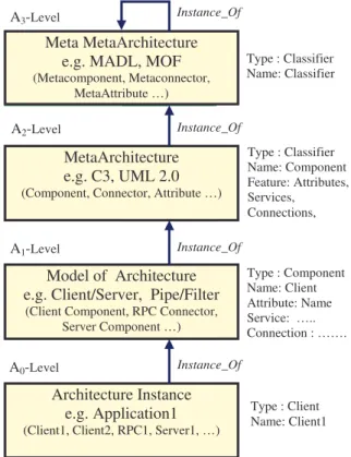
In the metamodeling hierarchy of we have only 4 architectural levels with instantiation mechanism. Thus, according to Figure 8.a, each level (Ai) must conforms with the description given above in A(i+1) level (instance-of relationship). The level A3 conforms to itself. Symmetrically, each level (Ai) describe the inferior level A(i-1). A0 is the end-level (run-time instance) [11]-[12].
A0 Level is the real word level (application level)
which is an instance of the architecture model level A1. At this level the developer has the possibility to select and instantiate elements any times as he needed to describe a complete application. Instances are created from element types which are defined at A1. Elements are created assembled with respect to the different constraints defined at A1.
A1 Level is also called architecture level. At this
level we have models of architecture, possibly with a given style, described using the language constructions or notations defined at A2 level (e.g. C3 metamodel). Thus, each architecture model is an instance of the metamodel defined in the above level.
A2 Level (meta-architecture level) defines the
language or the notation used to describe architectures at A1. This level is also used to modify or adapt the description language. All operations are undertaken at
this level will always be in conformance with the last level.
Fig. 8.a. Metamodeling hierarchy
A3 Level (meta meta-architecture) has the top level
concepts and elements used when we want to define any new architecture description language or new notation. In our previous work we have defined our proper meta meta-architecture model called MADL [13]. So, our C3 metamodel is defined in conformance with MADL. MADL is similar to MOF but component-oriented.
To connect architecture levels we define the following connector:
• Instance-Of Connector (IOC) is used to establish
connection among elements of a given level (model) with their classifier defined in the above level (metamodel). Figure 8.b represents the notation adopted.
Figure 8.b. IOC connector
Cpt2 Cpt21 SGC Sp ec ia lis at io n Gen era lis ati on Cpt22 Cpt23 C3 Meta Component Client IOC Data Base Manager Server A2-Level A1-Level Meta MetaArchitecture e.g. MADL, MOF
(Metacomponent, Metaconnector, MetaAttribute …)
MetaArchitecture e.g. C3, UML 2.0
(Component, Connector, Attribute …)
Model of Architecture e.g. Client/Server, Pipe/Filter
(Client Component, RPC Connector, Server Component …)
Architecture Instance e.g. Application1
(Client1, Client2, RPC1, Server1, …)
A3-Level A2-Level A1-Level A0-Level Instance_Of Instance_Of Instance_Of Instance_Of Type : Classifier Name: Classifier Type : Classifier Name: Component Feature: Attributes, Services, Connections, Type : Component Name: Client Attribute: Name Service: ….. Connection : ……. Type : Client Name: Client1
A. Amirat, M. Oussalah
Copyright © 2007 Praise Worthy Prize S.r.l. - All rights reserved International Review on Computers and Software, Vol. xx, n. x
V. Conclusion
The success of the component-construction paradigm in mechanical and electrical engineering has led to call its adoption in software development. To this end we have defined a minimal and a complete representation metamodel called C3 to describe software architecture and to reason about this architecture from different perspective view. The core elements of C3 are components, connectors and configurations. Elements are assembled using their interfaces. Syntactic and semantic corrections are carried out using respectively interfaces-matching and protocols-matching. Perspective views are defined by different kind hierarchies. Mainly, we use structural abstraction hierarchy to describe the structural decomposition hierarchy, behaviour description hierarchy to describe the behaviour decomposition, conceptual hierarchy to describe element libraries, the new elements generated by this type of hierarchy will be used to populate elements libraries, and finally the metamodeling hierarchy to show how we can modify the metamodel C3 and how to use it. Each hierarchy is supported and tooled by explicit connection mechanisms to provide the different form of connections required in each hierarchy. Structural hierarchy uses CDSC, ECC, and SAC connectors. Behavioural hierarchy uses CDBA, BIC and BAC connectors. Conceptual hierarchy uses SGC connector, and metamodeling hierarchy uses IOC connector.
Acknowledgements
We would like to thank the anonymous referees whose comments helped us to significantly improve the first version of this paper.
References
[1] N. Medvidovic, E. Dashofy, R. N. Taylor, Moving Architectural Description from Under the Technology Lamppost, Information
and Software Technology. Vol. 49, n. 1, pp. 12-31, 2007.
[2] R. N. Taylor, N. Medvidovic, , K. M. Anderson, E. J. Whitehead, J. E. Robbins, K. A. Nies, P. Oreizy, D. L. Dubrow, A Component- and Message-based Architectural Style for GUI Software, IEEE Transaction Software Engineering, Vol. 22, n. 6, pp. 390–406, 1996.
[3] J. E. Pérez-Martínez, Heavyweight Extensions to the UML Metamodel to Describe the C3 Architectural Style, ACM
SIGSOFT Software Engineering Notes, Vol.28, n. 3, pp. 5-15,
2003.
[4] A. Smeda, M. Oussalah, T. Khammaci, Improving
Component-Based Software Architecture by Separating Computations from Interactions, Proceedings of the 1st International Workshop on
Coordination and Adaptation Techniques for Software Entities, WCAT'04 held in conjunction with ECOOP, Oslo, Norway, June 2004.
[5] A. Amirat, M. Oussalah, T. Khammaci, Towards an Approach
for Building Reliable Architectures, Proceedings of IEEE
Information Reuse and Integration (IRI’07), Las Vegas, Nevada, USA, Pages 467-472, August 2007.
[6] M. Oussalah, A. Amirat, T. Khammaci, Software Architecture
Based Connection Manager, Proceedings of Software
Engineering and Data Engineering (SEDE’07), Las Vegas, Nevada, USA, Pages 194-199, July 2007.
[7] J. Matevska-Meyer, W. Hasselbring, R. Reussner, Software
Architecture Description Supporting Component Deployment and System Runtime Reconfiguration, Proceedings of Workshop
on Component-Oriented Programming WCOP 2004, Oslo, Norway, June 2004.
[8] M. Pinto, L. Fluentes, M. Troya, A Dynamic Component and Aspect-Oriented Platform, The Computer Journal, Vol.48, n. 4, pp. 401-420, 2005.
[9] D. Garlan, R. T. Monroe, D. Wile, Acme: Architectural Description Component-Based Systems, Foundations of Component-Based Systems, Cambridge University Press, pp. 47-68, 2000.
[10] A. Lanoix, D. Hatebur, M. Heisel, J. Souquières, Enhancing
Dependability of Component-Based Systems, Proceedings of
Ada-Europe, Lecture Notes in Computer Science Springer, ISBN 978-3-540-73229-7 pp. 41-54, 2007.
[11] OMG: Unified Modeling Superstructure [Electronic Version] from http://www.omg.org/docs/ptc/06-04-02.pdf, 2006. [12] OMG: Unified Modeling Language: Infrastructure [Electronic
Version] from http://www.omg.org/docs/formal/07-02-06.pdf, 2007.
[13] A. Smeda, M. Oussalah, , T. Khammaci, MADL: Meta
Architecture Description Language, Proceedings of the 3rd ICIS
International conference on Software Engineering Research, Management & Applications, SERA’05, Pleasant, Michigan, USA, Pages 152-159, August 2005.
Abdelkrim Amirat was born in Souk-Ahras,
Algeria in February, 1964. He received the Diploma of Ingénieur d’Etat and Magistere degrees in computer science, from Badji-Mokhtar University, Annaba, Algeria, in 1988 and 1991 respectively.
Actually he is a researcher at MODAL team, LINA Laboratory, University of Nantes, France. His research interests include requirement engineering, aspect oriented software development, component-based architecture, architecture description language, and architecture evolution. His contact address is: LINA Laboratory, CNRS FRE 2729, University of Nantes, 2, Rue de la Houssinière, BP 92208, 44322 Nantes, France, [email protected]
Mourad Oussalah is a professor at the
department of computer science and the head of the MODAL research group, LINA Laboratory, University of Nantes, France. His Interest include object oriented Software development, component-based systems, architecture modelling, and architecture evolution. His contact address is: LINA Laboratory, CNRS FRE 2729, University of Nantes, 2, Rue de la Houssinière, BP 92208, 44322 Nantes, France, [email protected]