HAL Id: hal-01011592
https://hal-mines-paristech.archives-ouvertes.fr/hal-01011592
Submitted on 28 Nov 2017
HAL is a multi-disciplinary open access
archive for the deposit and dissemination of
sci-entific research documents, whether they are
pub-lished or not. The documents may come from
teaching and research institutions in France or
abroad, or from public or private research centers.
L’archive ouverte pluridisciplinaire HAL, est
destinée au dépôt et à la diffusion de documents
scientifiques de niveau recherche, publiés ou non,
émanant des établissements d’enseignement et de
recherche français ou étrangers, des laboratoires
publics ou privés.
Pierre Weill, E. Lajeunesse, O. Devauchelle, F. Métivier, A. Limare, et al.. Experimental investigation
on self-channelized erosive gravity currents. Journal of Sedimentary Research, Society for Sedimentary
Geology, 2014, 84 (6), pp.487-498. �10.2110/jsr.2014.41�. �hal-01011592�
DOI: http://dx.doi.org/10.2110/jsr.2014.41
EXPERIMENTAL INVESTIGATION ON SELF-CHANNELIZED EROSIVE GRAVITY CURRENTS
PIERRE WEILL,1ERIC LAJEUNESSE,2OLIVIER DEVAUCHELLE,2FRANC¸ OIS ME´TIVER,2ANGELA LIMARE,2BENOIˆT CHAUVEAU,3ANDDOMINIQUE MOUAZE´4
1MINES ParisTech, PSL Research University, Centre de Ge´osciences, Fontainebleau, France
2Institut de Physique du Globe de Paris, Sorbonne Paris Cite´, Universite´ Paris Diderot, UMR 7154 CNRS, Paris, France 3IFP Energies Nouvelles, Rueil-Malmaison, France
4Morphodynamique Continentale et Coˆtie`re, Universite´ de Caen Basse-Normandie, UMR 6143 CNRS, Caen, France
e-mail: [email protected]
ABSTRACT: Submarine canyons are the main conduits for sediment transfer from continental shelves to deep abyssal plains. A
large number of bathymetric and seismic surveys provide detailed information on their morphology and structure, shedding light on the mechanisms involved in their formation. However, because of the difficulty in deploying instruments in deep marine environments, little is known about the processes by which turbidity currents erode and incise the canyon floors.
In this study, we use a micro-scale tank experiment to investigate the incision of a mobile sediment bed by a gravity current. We inject a brine at the top of a ramp covered with low-density plastic sediments. Conditions for channel formation are investigated through systematic exploration of the slope vs. discharge phase space. Measurements of the sediment bed topography and the gravity-current velocity profile allow us to characterize the channel incision dynamics. A channel forms when the bed shear stress exceeds the sediment critical shear stress. In this case, a channel starts forming near the upstream end of the incline and propagates down-slope while slowly deepening. After a transient state of about 1–2 hours, the channel reaches steady state. Experimental results suggest that the slope controls the rate of erosion and the speed of channel incision, while the brine discharge controls the channel geometry. The erosional morphologies created by our experimental gravity currents show strong analogies with the axial incision of canyons, the primary mechanism by which canyons connected to continental shelves or large rivers evolve.
INTRODUCTION
Submarine canyons indent the shelf edge to form steep-walled valleys, which are the main conduits for sediment transfer from continents and continental shelves to deep abyssal plains (Nittrouer and Wright 1994; Mulder et al. 2004). The formation of canyons is mainly due to mass wasting events and erosion by turbidity currents (Shepard 1981). The heads of canyons can either end on the shelf slope or connect directly with terrestrial rivers (Harris and Whiteway 2011). When connected to rivers or shelf sands, turbidity currents erode the canyon floor and form a characteristic V-shaped axial thalweg (Chiang and Yu 2006). Axial incision by turbidity currents has a key influence on canyon development as it triggers mass wasting processes that progressively enlarge and deepen the canyon valley (Baztan et al. 2005). On their downstream ends, canyons generally evolve in U-shaped aggrading channels which meander on the basin floor (Covault 2011).
To date, little is known about the processes by which turbidity currents erode and incise a channel. The relationships between the flow properties and the morphology of the resulting channel therefore remain obscure. Field surveys indeed face two major difficulties. First, direct measure-ments on active canyon floors are difficult to perform, because turbidity currents often damage instruments (Paull et al. 2003). Remote Doppler acoustic measurements of vertical velocity profiles have proved to be more efficient (Xu et al. 2004; Xu 2010), as well as simple current meters attached to mooring stations (Khripounoff et al. 2003, 2009; Canals et al. 2006). Second, the duration needed to form submarine canyons, on the
order of several tens of thousands of years (e.g. Amblas et al. 2011), prevents the observation of processes at a human timescale.
These difficulties have led researchers to turn toward experimental studies of gravity currents and turbidity currents. Most investigations use large-scale experiments (several meters) to investigate the connection between flow structure and sediment transport and deposition (Baas et al. 2004, 2005, 2009; Best et al. 2001; Buckee et al. 2001; Breien et al. 2010; McCaffrey et al. 2003). In most experiments, the flow is confined in a long and narrow glass-sided flume, sometimes ending on an expansion table (Baas et al. 2004). More recently, experiments have been carried out to study the behavior of turbidity currents in channel bends (Corney et al. 2006; Imran et al. 2007; Keevil et al. 2006; Straub et al. 2011; Kane et al. 2010). Several investigations have reported the formation of depositional morphologies such as the confinement of turbidity current by levee construction (Yu et al. 2006; Yu 2011; Rowland et al. 2010; Cantelli et al. 2011) or the formation of depositional gullies (Fedele and Garcia 2009). To the best of our knowledge, the formation of an erosional channelized morphology by a turbidity current has not yet been achieved experimen-tally. The challenge is to generate long-lived gravity currents capable of producing both erosion and deposition over long distances compared to the characteristic flow thickness. Indeed, the turbulence artificially created in mixing tanks to maintain sediment particles into suspension becomes damped quickly after the flow is released, causing the suspended particles to settle.
Me´tivier et al. (2005) showed that this problem can be circumvented by using a brine to model the density contrast of a turbidity current in a
Published Online: June 2014
micro-scale experiment (see also Lajeunesse et al. 2010). This is somehow equivalent to a gravity current in which the settling velocity of the suspension vanishes. The brine generates long-lived currents capable of incising the bed. Of course, depositional morphologies associated with the settling of suspended particles, such as levees, cannot be observed with this technique.
In the present study, we follow the same approach. We use the experimental setup developed by Me´tivier et al. (2005) with several improvements, which allow us to 1) obtain a better reproducibility of the experiments, 2) reduce the influence of initial and boundary conditions, and 3) get a better insight into the sediment transport and flow processes. A systematic exploration of the slope vs. discharge phase diagram allows us to define the conditions for channel inception. Measurements of the sediment bed topography and the gravity-current velocity profile allow us to characterize the channel incision dynamics and steady-state morphol-ogies. Finally, we discuss the upscaling to natural systems and propose an analogy between the experimental morphologies and axial incision by turbidity currents in natural canyons.
METHODOLOGY
Experimental Setup
The experiments were performed with the experimental setup developed by Me´tivier et al. (2005). It consists in a 0.5-m-deep,
2-m-long, and 0.5-m-wide tank, into which a 1-m-long and 0.5-m-wide ramp is immersed (Fig. 1). The adjustable slope of the ramp is measured with a digital inclinometer of accuracy 0.5u. The tank is filled with fresh water and a fine powder of plastic polymer (Arkema Rilsan Polyamide 11). The mean grain size of the sediment is D50 530 mm, and its density is
rs 5 1.08 (Table 1). The observation of sediment particles under a
microscope reveals that the grains are irregular flakes. In water, they form aggregates of size up to 100mm due to cohesion.
We begin each experimental run by stirring the fluid to suspend the particles. Once the fluid comes back to rest, the sediment settles into a homogeneous erodible bed which covers the ramp. The bed is a few centimeters thick. A brine of density rf 51.04 is then injected through a
tube located at the top of the incline (Fig. 1). A peristaltic pump maintains a constant brine discharge during the experiment, with an accuracy of 1 mL?min21.
We made several improvements to the initial apparatus of Me´tivier et al. (2005). In particular:
N
We modified the injection system so that the brine, injected frombelow the ramp, gently overflows on the sediment bed (see Fig. 1); this configuration strongly reduces the turbulent mixing at the outlet, as confirmed by conductivity measurements.
N
The introduction of an elevated floor 10 cm above the bottom of thetank prevents brine accumulation at the slope break, which would otherwise perturb the base-level conditions.
N
The experiments of Me´tivier et al. (2005) revealed that small irregularities on the initial sediment bed could trigger changes in the channel direction. To ensure the reproducibility of the experimental runs, we worked only with perfectly flat and regular initial sediment beds.N
We performed 17 experiments in total, at various slopes and discharges summarized in Table 2 (see also Fig. 2).Data Acquisition
The topography evolution was recorded during an experiment by projecting a fringe on the sediment bed (Limare et al. 2011). A video projector located above the water at the downstream end of the flume projected a sinusoidal fringe pattern on the ramp with an inclination of the order of 45u with respect to the horizontal (Fig. 1). A digital camera located above the area of interest recorded the fringe pattern which is
FIG. 1.—Experimental setup. The sediment is deposited on an adjustable ramp and an elevated floor. The optical system for topography acqui-sition is composed of a video projector that displays a fringe on the sediment surface and a digital camera. During some of the runs, we used an ultrasonic Doppler velocimeter to measure the velocity profile of the gravity current.
TABLE 1.— Physical properties of the brine and the sediment. The settling velocity is estimated from Stokes’ law, and critical stress from the Shields
curve (critical Shields number 5 0.3).
Flow Properties Density rf 1040 kg?m23 Temperature 20uC Dynamic viscosity 1.089 3 1023kg?m21?s21 Sediment Properties Grain size 30–100 mm Density rs 1080 kg?m23 Settling velocity ws 2.20 3 1025m?s21
modulated by the topography. The phase modulation was then calculated with a Fourier transform. Finally, a phase-unwrapping algorithm determined the phase distribution, which is proportional to the local deformation of the topography. Before running our experiments, we calibrated the measurement setup on a flat surface. This procedure allowed us to convert the phase map in the image coordinates into the relative elevation map in physical coordinates. In order to monitor the morphological evolution of the substrate, we performed topographic acquisitions every 10 to 15 minutes. Maps of net erosion and deposition were then obtained from the difference between the initial topography and the topography at the time of acquisition. To avoid diffraction by salted water, we interrupted the brine flow during each topography measurement. This procedure had no significant influence on the final bed morphology.
The progress of the gravity current down the ramp could be visualized by injecting dye into the brine. For several runs (Table 2), we also performed velocity measurements with an 8 MHz ultrasonic Doppler velocity profiler (UDVP). The probe was placed 4 cm above the bed and 50 cm downstream of the injection point. The ultrasonic beam propagated upstream at a 45u angle with the sediment bed (Fig. 1, insert). This ensured that the probe head was located above the free surface of the gravity current, and thus did not perturb the flow. The ultrasonic probe was held by an articulated arm mounted on rails. The diameter of the probe was 5 mm, and the diverging angle of the beam was 2.4u. The UDVP settings were adjusted to obtain a spatial sampling resolution of 0.2 mm. This technique allowed real-time measurements of the gravity-current thickness and velocity profile. For each measurement, 256 instantaneous velocity profiles were recorded at a frequency of 4 Hz, during about 60 s. A mean velocity profile was then calculated after data were filtered at one standard deviation.
RESULTS
Phenomenology
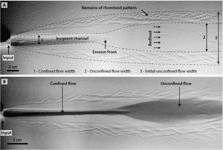
For each experiment, a gravity current first progressed down the ramp. Narrow near the inlet, it widened within the first 20 cm, and its width then
became apparently constant. The lateral extension of the gravity current is a function of the ramp slope, the discharge rate, and the flow density. Direct observations and colorimetric measurements show that the width of the current sufficiently far from the input increased linearly with the discharge rate (Lancien 2007; Lancien et al. 2007). On the contrary, it was a decreasing function of the bed slope and of the brine density. When the dense current reached the slope break, it decelerated, spread over the elevated floor, and progressively accumulated in the tank below the level of the elevated floor (Fig. 1). This design prevents brine accumulation at the slope break, and thus maintains constant boundary conditions at the base of the ramp.
When the bottom shear stress exerted by the gravity current exceeded the particle threshold of motion, erosion of the soft mobile bed occurred. Particles were transported downslope as bed load. The motion of sediment particles suggests that current velocity was higher at the center of the flow and decreased toward the sides. As a result, erosion was more intensive along the centerline of the flow. Once in motion, the grains travelled all the way down to the slope break where they were deposited, forming a prograding lobe which spread on the elevated floor (Fig. 3). The lateral extent of the deposit corresponds to the lateral extent of the current. Some retrogressive erosion also occurred at the slope break.
During the establishment of the gravity current, instabilities grew on the sediment bed. At first, diverging streaks of amplitude less than a millimeter, and wavelength around 4 mm, formed parallel to the flow direction. The formation of longitudinal streaks is commonly observed in wide channels with uniform sediment near the threshold of motion. It is often related to counterrotating vortices aligned with the primary flow (Colombini and Parker 1995). The amplitude of the streaks is generally of the order of one or two grain diameters, and the transverse spacing is invariably of the order of the flow depth. These longitudinal streaks later evolved into a rhomboid pattern similar to those reported on the swash zone of beaches, and reproduced experimentally in a shallow channel (Devauchelle et al. 2010a, 2010b). If the flow velocity was high enough, the rhomboid pattern evolved into low-amplitude, transversal sediment waves, which finally disappeared as the current reached steady state.
Because erosion is more intense near the center of the flow, the gravity current progressively embanked. Consequently the current thickness increased with time while its width decreased. A channel thus TABLE 2.— Experimental parameters. S 5 Slope. Q 5 Discharge rate /
input mass flux. NC 5 No Channel. EL 5 Erosion Limited. VM 5 Velocity Measurements. The numbers in the observation column
refer to the number of repeated experiments.
Exp. S (u) Q (mL?min21) Q (g.s21) Obs.
Exp_01 6 80 1.39 NC Exp_02 6 120 2.08 NC Exp_03 6 250 4.33 NC Exp_04 8 40 0.69 VM Exp_05 8 80 1.39 VM(4) Exp_06 8 120 2.08 VM Exp_07 8 160 2.77 VM Exp_08 8 200 3.47 VM Exp_09 8 240 4.16 EL Exp_10 10 40 0.69 VM Exp_11 10 80 1.39 VM(2) Exp_12 10 120 2.08 -Exp_13 10 160 2.77 -Exp_14 10 200 3.47 EL Exp_15 12 40 0.69 -Exp_16 12 80 1.39 -Exp_17 12 120 2.08 -Exp_18 12 160 2.77 EL Exp_19 14 40 0.69 -Exp_20 14 80 1.39 -Exp_21 14 120 2.08 EL
FIG. 2.—Phase diagram for channel formation considering the two control parameters of the experiments (slope and input mass flux), and comparison with the data of Me´tivier et al. (2005). For our experiments, no channel is formed below the solid line. Above the dashed line, the channel incision is limited by the thickness of sediment bed.
progressively developed a few centimeters after the injection point and propagated downstream with a sharp erosion front (Fig. 4). The channel width, about one or two centimeters, was selected during the early stage of the channel development. In comparison, the initial lateral extent of the unconfined gravity current was more than 10 cm. The channel depth increased with time until the current was confined within the channel. As the channel progressed downslope, the unconfined gravity current at the slope break narrowed. Consequently, the sediment deposits were focused on the fan apex. When the channel reached the slope break, it reincised the sediment deposit and propagated over the elevated floor until the current slowed down (Fig. 5).
With time, sediment transport decreased and eventually vanished, thus ending the experiment. All runs produced the same morphological units (Fig. 5):
N
rhomboid patterns on the sediment bed extending over the entire width of the unconfined gravity current;N
a straight channel of constant width and depth running from the injection point to the slope break;N
retrogressive erosion patterns at the slope break;N
a sediment lobe on the elevated floor associated with the channelprogression.
Evolution of Topography and Gravity-Current Properties The morphological evolution of the sediment bed was surveyed by regular topography measurements during the experiment. We monitored the gravity-current properties during the channel incision with continuous UDV profile measurements, and by direct observation of the dyed current. Figure 6 shows the evolution of the cumulated erosion and deposition (in millimeters) during Exp_10 (Fig. 2, Table 2).
At the beginning of the experiment, erosion occurred on the first centimeters of the ramp along the flow direction. We did not observe any erosion or deposition over the remaining part of the ramp. The sediment eroded near the inlet seemed to bypass the ramp. At the downstream end of the ramp, a 1-cm-high step at the slope break caused the flow to accelerate before it spread over the horizontal surface, and finally decelerated and lost its competence. As a result, we observed retrogressive erosion over a few centimeters upstream of the slope break with a lateral extent equalling the width of the dense current at the end of the slope. The erosional morphology features parallel furrows oriented in the flow direction, with a well-defined lateral wavelength of about one centimeter. The sediment eroded near the injection point and transported across the ramp, as well as the sediment eroded in the retrogressive erosion zone, was deposited at the slope break. In the first minutes of the experiment, the lobe deposit was wide (maximum lateral extension of the flow) and short.
After 20 to 30 minutes, a distinct channel formed in the upper part of the ramp. Its width remained constant as it deepened with time. The downstream part of the channel ended with a smooth eroding front progressing downstream at about a centimeter per minute.
As the channel progressed downslope, the unconfined flow at the downstream end of the ramp narrowed. As a result, sediments were deposited over a diminishing area on the elevated floor. This phenom-enon explains the shape of the sediment lobe.
Once the erosion front reached the elevated floor, it reincised the sediment lobe, and its position quickly stabilized. The channel width was constant along the ramp. The channel depth also tended towards steady states as sediment transport ceased. After two hours, the bed morphology no longer evolved. In steady state, injecting dye at the inlet revealed that most of the brine was confined to the channel.
For several experiments reported in Table 2, we measured velocity profiles before, during, and after channel incision. Figure 7 (see also
FIG. 3.—Sediment lobe deposited at the slope break. Rhomboid patterns on the ramp provide an estimate of the width of the gravity current before channelization. Retrogressive erosion occurs at the slope break.
Table 3) shows velocity profiles measured first before incision (uncon-fined flow), and later in the channel (con(uncon-fined flow). The general shape of the profiles is in good agreement with the results of Lancien et al. (2007): the velocity increased linearly from the bed to a maximum value 2 or 3 millimeters above the bed, and decreased smoothly above this point. The velocity decayed over a few millimeters for unconfined flows, and over a few tens of millimeters for confined ones. As long as the flow was unconfined at the measurement location (typically during the first tens of
minutes), its velocity was of the order of 10 mm?s21and the current
thickness was small (typically 1 cm). Once the flow was confined, its velocity was four to five times larger, and the flow was also about two times thicker. According to the brine mass balance, the confined flow should be 8 to 10 times narrower than the unconfined one, which is in good agreement with direct observations (Fig. 5).
Both before and after the flow confinement, the Reynolds number was typically below 300 (Table 4), and the Froude number was less than 0.2.
FIG. 4.—Downslope propagation of the channel (flow is from left to right): A) 20 min after the beginning of the experiment and B) 40 minutes after the beginning of the experiment. In the second picture, the gravity current is visualized by injecting dye in the brine. Exp_04: discharge 5 40 mL?min21and slope 5 8u.
Unconfined and confined flows were therefore laminar and subcritical. It is thus likely that mixing at the brine surface by water entrainment was limited. Therefore, the flow discharge should be conserved downslope. The flow being laminar, the streamwise component of the bottom shear stress reads:
tbjx~m du=dz ð1Þ
where m is the dynamical viscosity of the brine, equal to 1.089 3 1023kg?m21?s21under the present conditions of temperature and salinity (Sharqawy et al. 2010).
The evolution of the streamwise bottom shear stress is compared to that of the channel depth in Figure 8. As long as the channel erosion front was far upstream from the measurement point, the flow was unconfined, the shear stress remained low (less than 0.01 N?m22), and no erosion
FIG. 6.—Map of the cumulated erosion and deposition for experiment Exp_10 (initial slope 10u, input discharge rate 40 mL?min21). 75 minutes after the beginning of the experimental run, the topography has almost reached steady state and sediment transport has virtually vanished. Erosion is represented in cold colors, and deposition in warm colors.
FIG. 7.—Velocity profiles measured along the direction normal to the bed, at 50 cm from the inlet during the experiment Exp_10 (40 mL?min21, 10u). Dark gray: 24 minutes after the beginning of the experiment, the channel erosion front is far upstream of the measurement location; the flow is unconfined. Light gray: 109 minutes after the beginning of the experi-ment, the channel has reached the downstream end of the slope, and the lower part of the flow is confined in the channel.
occurred. Topography measurements revealed a slight elevation of the sediment bed at the measurement point, which could correspond to the layer of particles moving as bedload. To avoid diffraction, the brine injection was turned off during each topography acquisition. As a result, the transported particles settled, and accreted on the bed. The deposited layer was reeroded as the injection was turned back on. The fact that, at this stage of the experiment, no erosion occurred while sediment was transported reveals that the bottom shear stress was very close to the critical shear stress for grain motion. Calculated Shields parameters for the unconfined flows range between 0.3 and 0.5 (Table 4).
When the channel erosion front approached the measurement point (at 40 minutes, Fig. 8), the shear stress increased to 0.01 N?m22, triggering erosion. The channel deepened as erosion increased, but its width remained constant. The shear stress increased linearly as the flow became confined. The rate of channel incision was not constant, but seems to follow an exponential decay: the incision was fast at the beginning, and slowed down as it reached steady state.
Both the bottom shear stress and the channel depth eventually stabilized: the morphology had reached steady state. The gravity current continued to flow downslope at constant velocity, but no sediment was visibly transported any more.
Influence of Bed Slope and Mass Flux
As previously reported by Me´tivier et al. (2005), the ability of the gravity current to form a channel depends on both the flow rate and the initial slope. Figure 2 reports the slope and discharge conditions for which we observed the formation of a channel. Channel incision occurred when the discharge was larger than some threshold. This threshold discharge decreased when the initial slope of the incline was increased. At large slopes and discharges, the sediment layer was eroded down to the acrylic plastic surface, thus preventing the channel from reaching its steady-state morphology.
Our observations appear to contradict those of Me´tivier et al. (2005), who reported that channel incision occurs for discharges smaller than a threshold value (Fig. 2). We believe that the observations of Me´tivier et al. (2005) result from an experimental artifact: the authors report strong turbulent mixing near the brine inlet. This turbulent mixing, especially intense at high discharges, dilutes the gravity current and weakens
erosion. In the present study, however, the injection device was modified so that the brine, injected from below the ramp, gently overflowed on the sediment bed, thus reducing turbulent mixing. The amplitude of dilution can be represented by the dilution factor DF 5 dr/dr0, where dr (resp.
dr0) is the difference between the density of the diluted brine (resp. the
nondiluted brine) and the density of fresh water. We measured the dilution factor by refractometry near the inlet for both our experimental setup and that of Me´tivier et al. (2005) (Lancien 2007). For Me´tivier et al. (2005), the dilution factor at the inlet outflow was 0.6, and dropped to 0.2 for discharges greater than 4 g?s21. In the present study, the dilution
factor remained above 0.8 for discharges as high as 10 g?s21.
Finally, Me´tivier et al. (2005) reported the formation of mildly meandering channels for low brine discharge and high slopes (Fig. 2). In the present study, all channels were straight. We suspect that the meandering reported in Me´tivier et al. (2005) might have been triggered by irregularities of the initial bed. With the smooth bed of the present study and the improved injection system, the gravity current flowed along the steepest direction and formed straight channels.
Steady-State Morphology
For each experiment forming a steady-state channel, we used the digital elevation model acquired with the fringe projection technique to extract the channel longitudinal profile and its cross section.
Longitudinal Profiles.—Longitudinal profiles were obtained by plotting the elevation of the channel bed in steady state against the distance from the inlet. The longitudinal profiles were compared with the initial slope before incision. Most of them are linear, although some of them show a slightly concave shape. Apart from the extremities of the channels, the incision depth was roughly constant. When the initial slope was high, the incision depth increased slightly with distance from the inlet, likely indicating an acceleration of the current, and thus an increase of its erosion capacity. On the contrary, when the water discharge was high and the slope was low, the erosion near the source was stronger. We interpret this as a loss of competence of the current due to dilution, because high discharge rates might increase water mixing.
Longitudinal profiles reveal that, for a given discharge rate, the channel slope at steady state depends on the initial slope. Exp_05 and Exp_16 (Tab. 2) were run with a discharge of 80 mL?min21and with an initial bed slope of 8u and 12u, respectively. Both longitudinal profiles are linear in steady state (Fig. 9). In Exp_05, the incision depth is constant along the channel path, when compared to the initial bed surface (dashed line). For Exp_16, with a steeper initial slope, erosion increased slightly down-stream. More generally we observe that, in all our experimental runs, the slope of the final channel remained close to the inclination of the initial ramp. This suggests that the final channel longitudinal slope value is not the parameter controlling the morphological steady state of the system.
Channel Cross Sections.—We used the digital elevation model (DEM) to compute, whenever possible, the average cross section of the steady-TABLE 3.—Average current velocity and thickness before and after channel incision. Because of the poor quality of the data on the upper part of the flow,
only rough estimates of the current thickness are provided.
Unconfined Flow Confined Flow
Exp. S (u) Q (mL?min21) Umean(mm?s 21 ) Umax(mm?s 21 ) H (mm) Umean(mm?s 21 ) Umax(mm?s 21 ) H (mm) Exp_05 8 80 4.7 10.9 10 14.0 39.1 20 Exp_06 8 120 3.3 10.3 10 12.2 71.2 20 Exp_07 8 160 5.4 11.4 10 14.2 68.5 20 Exp_10 10 40 3.7 8.3 10 8.2 26.9 20 Exp_11 10 80 3.8 11.9 10 13.8 40.6 20
TABLE 4.—Reynolds numbers, Froude numbers, and Shields parameters of
unconfined and confined flows for the experiments reported in Table 3.
Unconfined Flow Confined Flow
Exp. Re Fr H Re Fr H Exp_05 47 0.08 0.40 280 0.16 1.81 Exp_06 33 0.05 0.38 244 0.14 3.29 Exp_07 54 0.09 0.42 284 0.16 3.17 Exp_10 37 0.06 0.31 164 0.09 1.24 Exp_11 38 0.06 0.44 276 0.16 1.88
state channel. To do so, we averaged 220 regularly spaced cross sections. They were located between 40 and 60 cm from the inlet, i.e., sufficiently far from both the inlet and the slope break so that their shape was not influenced by the boundary conditions. The averaged cross sections exhibit a symmetric V shape with steep banks (Fig. 10).
Comparing different runs allows us to draw several qualitative observations. First, the total amount of eroded sediment increases with the discharge. Consequently, large discharges cause larger channels. Secondly, the initial slope influences significantly neither the shape nor the size of the steady-state channel. It does, however, influence the erosion rate. Indeed, we observe that for a given discharge, the duration of the transient toward steady state decreases when the initial slope of the ramp increases. Finally, the initial slope appears to influence also the history of the channel incision.
At steep initial slopes (typically more than 10u), the channel formation can be divided into two phases. During the first phase, the shear stress exceeds the threshold of grain entrainment over almost the entire width of
the gravity current. As a result, the gravity current incises the sediment bed over its entire width (typically several centimeters). Shear stress and consequently sediment transport are, however, more intense near the center of the current. Therefore the gravity current gradually embanks itself into a narrower channel. During this second phase, the gravity current develops a narrower secondary channel. These incision phases generate morphology with embedded channels, as illustrated in Fig-ure 10C and D. For initial slopes smaller than 10u, only the central part of the gravity current generates enough shear stress to exceed the threshold of grain entrainment. Consequently, the gravity current erodes the sediment bed over an initial width of the order of the steady-state width. The channel incision then involves only one phase, and produces the morphologies shown in Figure 10A and B.
We now use the averaged cross sections to extract the mean channel width and depth as defined in Figure 10D. The resulting width and depth is plotted as a function of discharge in Figure 11. Both the channel width and depth increase linearly with the discharge, although the channel
FIG. 8.—Evolution of bottom shear stress and channel depth through time for Exp_10 (40 mL?min21, 10u). Left: Bottom shear stress and channel depth measured at
50 cm from the inlet. Right: Evolution of the channel cross section at the measurement location.
FIG. 9.—Longitudinal profiles of channels at steady state for two runs (Exp_05 and Exp_16) with identical discharges but distinct initial slopes. Dashed lines represent initial bed surfaces before the beginning of the channel incision.
depths are more scattered. The steady-state cross-section area increases with increasing discharge. The mean aspect ratio W/H computed for the investigated channels is 3.7, corresponding to a cross-stream bank slope of 28.4u, close to repose angle. Again, the initial slope has no influence on the final morphology of the channel.
DISCUSSION
The conditions of our experiment differed greatly from natural conditions (low Reynolds numbers, no sediment in suspension, etc.). Since there is no rigorous similitude scaling between our experiment and natural systems, we cannot draw a quantitative analogy between our observations and field observations. Still, some of the conclusions drawn from our experiments might provide qualitative insights into the physical processes driving the inception and the development of erosional submarine morphologies by turbidity currents.
Channelized morphologies can be formed on the ocean bottom by dense water currents, for instance in the Bosporus Strait between the Black Sea and the Mediterranean Sea (Go¨kas¸an et al. 2005). However, the aim of our experiments was to give insights into the physical processes and mechanisms that drive the inception and the development of erosive submarine morphologies by turbidity currents.
Erosive morphologies associated with turbidity currents are found in steep environments, typically on the shelf edge and shelf slope, mainly in the form of submarine canyons. For several decades, there has been a debate concerning the origin of submarine canyons (Kuenen 1953; Pratson et al. 1994). Do they result from sediment mass failures and retrogressive headward erosion, or are they initiated by downslope sediment flows? Both processes are involved, but their relative importance depends on the nature of the submarine canyon. In fact, two types of canyons can be distinguished (Harris and Whiteway 2011; Mitchell 2005, 2008; Lo Iacono et al. 2011): slope canyons and shelf-indenting canyons. Slope canyons (or blind canyons) are confined to the continental slope, below the shelf break. They are immature canyons that grow mainly by mass failure and retrogressive erosion. Failed sediments turn into turbidity currents by incorporating water. Assuming that failures occur homogeneously along the canyon walls, the occurrence frequency of turbidity currents, and thus erosion, increase along the canyon. The downstream increase in erosion is correlated to a decrease in slope, resulting in a concave-upward longitudinal profile (Mitchell 2005).
Shelf-indenting canyons are considered more mature systems, and are fed mainly at the canyon head by shelf sands reworked by storms (Salles et al. 2008; Lastras et al. 2009), by dense-water cascading (Canals et al. 2006; Gaudin et al. 2006; Puig et al. 2008), or by river-laden sediments (Babonneau et al. 2002; Hagen et al. 1996; Savoye et al. 2009; Chiang and Yu 2006; Noda et al. 2008). Here, the volume and erosive power of turbidity currents are roughly constant along the canyon path, resulting in linear longitudinal profiles (Pratson and Coakley 1996; Mitchell 2005). Several morphological elements indicate that these canyons were formed by downslope erosive turbidity flows: tortuous paths around bathymetric highs, as opposed to retrogressive erosion, which progresses upslope along a straight path (Ratzov et al. 2012; Gee and Gawthorpe 2007), reuse of existing downslope conduits by present-day canyons (Pratson et al. 1994). Downslope erosion is especially efficient during sea-level low stands, when more or less direct connections between rivers and canyon
FIG. 10.—Steady-state cross-section average over 220 profiles for four different experiments: A, B) Single-phase channel incision at low slope values, C, D) Two-phase channel incision at high slope values. The definitions of both the channel width and depth are illustrated in Part D.
FIG. 11.—Steady-state channel width (full symbols) and depth (empty symbols) as a function of the discharge. The symbols represent the initial slope. Error bars are 4 mL?min21for the discharge rate, 2 mm for the channel width, and 0.5 mm for
heads are possible. Bathymetric and seismic surveys revealed that most shelf-indenting canyons experienced a polyphase history of infilling during sea-level high stands, and rejuvenation by axial incision of downslope erosive turbidity flows during sea-level low stands, when canyon heads were connected to rivers and detrital supply was high (Baztan et al. 2005; Gaudin et al. 2006; Popescu et al. 2004, Lastras et al. 2009; Chiang and Yu 2011). Modern axial incisions generally erode poorly consolidated Pleistocene sediments. They feature V-shaped cross sections (Fig. 12), with rather steep sides (5u to 20u slopes). The incision depth and width range between 40 and 150 m, and between 300 and 700 m, respectively. Recently, Fildani et al. (2013) proposed, in a study combining high-resolution bathymetric images and outcrop analogues, that aggradational leveed channels are also erosional at inception. They suggest that turbidity currents are able to construct aggrading levees only after a phase of flow confinement by erosional cutting into the substrate, where a thalweg develops downstream from the coalescence of cyclic erosional steps.
Our experiments show strong similarities with axial incisions, both in terms of processes and morphology: a long-lived gravity current with a direct connection to the source, downslope-propagating erosion triggered by the gravity current only without retrogressive erosion, incision into a soft sediment substrate, and V-shape cross sections with steep channel sides. The experiments reveal that, when the conditions for incision are met, the channel morphology eventually reaches steady state, with a constant width and depth.
Because water mixing and diffusion at the surface of the current are negligible, and because there are no tributaries to the main channel, the erosive power of the gravity current is constant along the channel path, except near the inlet (respectively near the slope break), where the flow accelerates (respectively decelerates). Moreover, the sediments are homogeneous along the ramp. As a consequence, the incision depth is constant along the channel, resulting in a linear longitudinal profile. This is reminiscent of natural canyons fed by shelf sands or river-laden sediments, which exhibit linear longitudinal profiles (Mitchell 2005).
The steady-state cross section of rivers has been widely studied since the pioneering work of Lane (1937, 1955) and Henderson (1961) and the theory of stable-channel design. This theory predicts the steady-state shape of an alluvial river, assuming that all particles on the channel bed are at the threshold of motion (Singh 2003). Near the water surface, the banks are at the angle of repose. In the middle of the channel, the flow-induced shear stress causes incipient motion. At intermediate locations, the threshold conditions are maintained by the combined action of shear stress and gravity.
In the present experiments, the steady-state channel is somehow similar to a terrestrial river. No sediment erosion or deposition is observed, and
since there is no sediment feeding at the input source, no sediment is transported. This implies that the flow-induced shear stress decreases during the channel incision, until it reaches a value close to the threshold shear stress. Similar observations are reported in micro-scale and laminar experimental rivers (Malverti et al. 2008; Seizilles et al. 2013), where the threshold theory predicts the cross section of the river in steady state.
This model, however, does not match the data collected using the ultrasonic Doppler velocimeter. Figure 8 shows an example of the evolution of the bottom shear stress during the incision process. Erosion starts when the bottom shear stress exceed a threshold value of approximately 5 3 1023N?m22, which can be considered as an estimate
of the threshold shear stress. If we compare this value to the threshold Shields parameter in a viscous flow, which value is around 0.3, we obtain a value of critical shear stress ranging from 3.5 3 1023to 12 3 1023N?m22 for a grain size between 30 and 100 mm. Both estimates are in good agreement. As the channel deepens, the flow becomes more confined and thicker (Fig. 7), and the flow velocity increases by a factor of two or three. When the channel has reached steady state, the velocity stabilizes. Measured values of bottom shear stress on the channel bed appear to be several times higher than the bottom shear stress exerted by the unconfined flow (Fig. 8), and thus several times higher than the critical shear stress for grain motion.
These observations are in contradiction with the threshold hypothesis. Several hypotheses can be proposed to account for this behavior, but further investigations would be necessary to confirm them.
A first possibility would be to question the validity of velocity measurements close to the channel bed. The probe diameter is 5 mm, with a beam diverging angle of 2.4u. Considering the average length of the beam used for our measurements (50 mm), the diameter of the beam near the bed was about 7 mm. The validity of the measurements might be questionable when velocity profiles are sampled in channels narrower than the beam width. A zone of low velocity in the deepest part of the channel would be difficult to distinguish from erroneous measurements collected in the sediment bed. If the top of the low-velocity zone is interpreted as the sediment bed surface, then the bottom shear stress would be greatly overestimated.
Another possible explanation would be that the grain critical shear stress is not constant and increases with depth as a result of grain-size sorting and compaction during bed preparation. The upper bed layer, consisting of the finest particles, full of water and uncompacted would have a very low threshold of motion, while the sediment on the channel bed would be coarser and compacted by the weight of the overlying sediment. However, this hypothesis is less plausible because: (i) little time was left for the sediment to compact between bed preparation and the
attributed to the Late Glacial Maximum (LGM). D60 erosion surface is correlated to the low sea level of Marine Isotopic Stage 6 glacial maxi-mum. Modified from Baztan et al. (2005).
beginning of the experiments (less than a day); (ii) several tests were carried out with different bed-preparation methods (including hand preparation with a scraper, to avoid sediment sorting and differential compaction), and showed the same behavior.
If the experiments clearly show that all conditions favorable to channel inception lead to a V-shaped cross section in steady state, the available data on the flow hydrodynamics do not allow us to explain this morphology. It is likely that, as the V-shaped channels get deeper and narrower, the cross-sectional geometry plays an increasing role in the velocity distribution, which we cannot observe with our velocity measurements.
CONCLUSION
Due to the challenges associated with the deployment of instruments in deep marine environments, little is known about the processes by which turbidity currents incise submarine canyons. Here, we study the incision of a mobile sediment bed by a laminar gravity current in an experimental micro-scale tank. The use of a brine flow to model a sediment-laden turbidity current allows us to generate experimental long-lived gravity currents capable of eroding the sediment bed over long distances. Measurements of both the bed topography and the flow velocity profile reveal that once the shear stress exerted by the current is strong enough to trigger erosion, a straight erosional channel progresses downslope until it reaches a steady-state morphology in equilibrium with the flow.
We suspect that the channel evolves towards its final steady-state morphology through gradual decrease of the shear stress. The steady-state morphology is then reached when the shear stress equals the critical shear stress for grain motion inside the channel. This mechanism successfully predicts the shape of experimental laminar rivers. In the present study, however, the spatial resolution of our velocity probe is not accurate enough to test this hypothesis unambiguously.
Morphometric analysis reveals that the width and depth of the steady-state channel are controlled primarily by the brine discharge. The initial slope of the sediment bed appears to exert no significant control on the final morphology. It does, however, control both the incision rate and the time needed to reach steady state.
Finally, our laboratory channels show similarities with axial incisions in submarine canyons, in terms of both morphology (V-shaped canyons) and processes of initiation (long-lived hyperpycnal flow and subsequent prograding erosion of the sediment bed). This suggests that our micro-scale experiments could simulate erosion over long periods of time (several thousands of years), and that turbulence and suspended sediment are not always necessary for bed erosion and channel formation. Still, further work is required to formalize the scaling of the experiment in terms of nondimensional parameters.
ACKNOWLEDGMENTS
This work has been funded by IFP Energies Nouvelles. The experiments were carried out within the Geomorphology group (Geological Fluid Dynamics team) of the IPGP (Institut de Physique du Globe de Paris). We thank reviewers and editors for their helpful suggestions which greatly improved this manuscript. I am grateful to the technical staff that provided essential support for the experimental setup design and data acquisition: He´le`ne Bouquerel, Yves Gamblin, Thierry Rivet, and Antonio Vieira. The UDV probe was kindly provided by the Coastal and Continental Morphodynamics laboratory, University of Caen Basse-Normandie, France.
REFERENCES
AMBLAS, D., GERBER, T.P., CANALS, M., PRATSON, L.F., URGELES, R., LASTRAS, G.,AND
CALAFAT, A.M., 2011, Transient erosion in the Valencia Trough turbidite systems,
NW Mediterranean Basin: Geomorphology, v. 130, p. 173–184.
BAAS, J.H., VANKESTEREN, W.,ANDPOSTMA, G., 2004, Deposits of depletive
high-density turbidity currents: a flume analogue of bed geometry, structure, texture: Sedimentology, v. 51, p. 1053–1088.
BAAS, J.H., MCCAFFREY, W.D., HAUGHTON, P.D.W.,ANDCHOUX, C., 2005, Coupling
between suspended sediment distribution and turbulence structure in a laboratory turbidity current: Journal of Geophysical Research, v. 110, p. 1–20.
BAAS, J.H., BEST, J.L., PEAKALL, J., AND WANG, M., 2009, A phase diagram for turbulent, transitional, and laminar clay suspension flows: Journal of Sedimentary Research, v. 79, p. 162–183.
BABONNEAU, N., SAVOYE, B., CREMER, M.,AND KLEIN, B., 2002, Morphology and architecture of the present canyon and channel system of the Zaire deep-sea fan: Marine and Petroleum Geology, v. 19, p. 445–467.
BAZTAN, J., BERNE´, S., OLIVET, J.-L., RABINEAU, M., ASLANIAN, D., GAUDIN, M., RE´HAULT, J.-P., AND CANALS, M., 2005, Axial incision: the key to understand submarine canyon evolution (in the western Gulf of Lion): Marine and Petroleum Geology, v. 22, p. 805–826.
BEST, J.L., KIRKBRIDE, A.D.,ANDPEAKALL, J., 2001, Mean flow and turbulence structure
of sediment-laden gravity currents: new insights using ultrasonic Doppler velocity profiling, in McCaffrey, W., Kneller, B., and Peakall, J., eds., Particulate Gravity Currents: International Association of Sedimentologists, Special Publication 31, p. 159–172.
BREIEN, H., DEBLASIO, F.B., ELVERHOI, A., NYSTUEN, J.P.,ANDHARBITZ, C.B., 2010,
Transport mechanisms of sand in deep-marine environments: insights based on laboratory experiments: Journal of Sedimentary Research, v. 80, p. 975–990. BUCKEE, C., KNELLER, B.,ANDPEAKALL, J., 2001, Turbulence structure in steady,
solute-driven gravity currents, in McCaffrey, W., Kneller, B., and Peakall, J., eds., Particulate Gravity Currents: International Association of Sedimentologists, Special Publication 31, p. 173–187.
CANALS, M., PUIG, P., DURRIEU DEMADRON, X., HEUSSNER, S., PALANQUES, A.,AND
FABRES, J., 2006, Flushing submarine canyons: Nature, v. 444, p. 354–357. CANTELLI, A., PIRMEZ, C., JOHNSON, S.,ANDPARKER, G., 2011, Morphodynamic and
stratigraphic evolution of self-channelized subaqueous fans emplaced by turbidity currents: Journal of Sedimentary Research, v. 81, p. 233–247.
CHIANG, C.-S.,ANDYU, H.-S., 2006, Morphotectonics and incision of the Kaoping
submarine canyon, SW Taiwan orogenic wedge: Geomorphology, v. 80, p. 199–213. COLOMBINI, M., AND PARKER, G., 1995, Longitudinal streaks: Journal of Fluid
Mechanics, v. 304, p. 161–183.
CORNEY, R.K.T., PEAKALL, J., PARSONS, D.R., ELLIOTT, L., AMOS, K.J., BEST, J.L., KEEVIL, G.M.,ANDINGHAM, D.B., 2006, The orientation of helical flow in curved channels: Sedimentology, v. 53, p. 249–257.
COVAULT, J.A., 2011, Submarine fans and canyon-channel systems: a review of processes, products, and models: Nature Education Knowledge, v. 3, p. 4. DEVAUCHELLE, O., MALVERTI, L., LAJEUNESSE, E., JOSSERAND, C., LAGRE´E, P.-Y.,AND
ME´TIVIER, F., 2010a, Rhomboid beach pattern: a laboratory investigation: Journal of Geophysical Research, Earth Surface, v. 115, F02017, doi: 10.1029/2009JF001471. DEVAUCHELLE, O., MALVERTI, L., LAJEUNESSE, E., LAGRE´E, P.-Y., JOSSERAND, C.,AND
NGUYENTHU-LAM, K.-D., 2010b, Stability of bedforms in laminar flows with free
surface: from bars to ripples: Journal of Fluid Mechanics, v. 642, p. 329–348. FEDELE, J.J.,ANDGARCIA, M.H., 2009, Laboratory experiments on the formation of
subaqueous depositional gullies by turbidity currents: Marine Geology, v. 258, p. 48– 59.
FILDANI, A., HUBBARD, S.M., COVAULT, J.A., MAIER, K.L., ROMANS, B.W., TRAER, M.,
ANDROWLAND, J.C., 2013, Erosion at inception of deep-sea channels: Marine and Petroleum Geology, v. 41, p. 48–61.
GAUDIN, M., BERNE´, S., JOUANNEAU, J.-M., PALANQUES, A., PUIG, P., MULDER, T., CIRAC, P., RABINEAU, M.,ANDIMBERT, P., 2006, Massive sand beds attributed to deposition by dense water cascades in the Bourcart canyon head, Gulf of Lions (northwestern Mediterranean Sea): Marine Geology, v. 234, p. 111–128.
GEE, M.J.R., ANDGAWTHORPE, R.L., 2007, Early evolution of submarine channels offshore Angola revealed by three-dimensional seismic data, in Davies, R.J., Posamentier, H.W., Wood, L.J., and Cartwright, J.A., eds., Seismic Geomorphology: Applications to Hydrocarbon Exploration and Production: Geological Society of London, Special Publication 277, p. 223–235.
GO¨ KAS¸AN, E., TUR, H., ECEVITOG˘ LU, B., GO¨ RU¨M, T., TU¨ RKER, A., TOK, B., C¸ AG˘ LAK, F., BIRKAM, H.,ANDS¸IMS¸EK, M., 2005, Evidence and implications of massive erosion
along the Strait of Istambul (Bosphorus): Geo-Marine Letters, v. 25, p. 324–342. HAGEN, R., VERGGRA, H.,ANDNAAR, F., 1996, Morphology of San Antonio submarine
canyon on the central Chile forearc: Marine Geology, v. 129, p. 197–205. HARRIS, P.T.,ANDWHITEWAY, T., 2011, Global distribution of large submarine canyons:
Geomorphic differences between active and passive continental margins: Marine Geology, v. 285, p. 69–86.
HENDERSON, F.M., 1961, Stability of alluvial channels: Journal of the Hydraulics Division, American Society of Civil Engineers, Proceedings, v. 87, p. 109–138. IMRAN, J., ISLAM, M.A., HUANG, H., KASSEM, A., DICKERSON, J., PIRMEZ, C.,AND
PARKER, G., 2007, Helical flow couplets in submarine gravity underflows: Geology, v. 35, p. 659–662.
KANE, I.A., MCCAFFREY, W.D., PEAKALL, J.,ANDKNELLER, B.C., 2010, Submarine
channel levee shape and sediment waves from physical experiments: Sedimentary Geology, v. 223, p. 75–85.
KEEVIL, G.M., PEAKALL, J., BEST, J.L.,ANDAMOS, K.J., 2006, Flow structure in sinuous
submarine channels: velocity and turbulence structure of an experimental submarine channel: Marine Geology, v. 229, p. 241–257.
LANE, E.W., 1955, Design of stable canals: American Society of Civil Engineers,
Transactions, v. 120, p. 1234–1260.
LASTRAS, G., ARZOLA, R.G., MASSON, D.G., WYNN, R.B., HUVENNE, V.A.I.,
HU¨ HNERBACH, V.,ANDCANALS, M., 2009, Geomorphology and sedimentary features
in the Central Portuguese submarine canyons, Western Iberian margin: Geomor-phology, v. 103, p. 310–329.
LIMARE, A., TAL, M., REITZ, M.D., LAJEUNESSE, E.,ANDME´TIVIER, F., 2011, Optical
method for measuring bed topography and flow depth in an experimental flume: Solid Earth, v. 2, p. 143–154.
LOIACONO, C., SULLI, A., AGATE, M., LOPRESTI, V., PEPE, F.,ANDCATALANO, R., 2011,
Submarine canyon morphologies in the Gulf of Palermo (Southern Tyrrhenian Sea) and possible implications for geo-hazard: Marine Geophysical Research, v. 32, p. 127–138.
MALVERTI, L., LAJEUNESSE, E.,ANDME´TIVIER, F., 2008, Small is beautiful: Upscaling from microscale laminar to natural turbulent rivers: Journal of Geophysical Research, Earth Surface, v. 113, no. F04004, doi: 10.1029/2007JF000974.
MCCAFFREY, W.D., CHOUX, C.M., BAAS, J.H.,ANDHAUGHTON, P.D.W., 2003, Spatio-temporal evolution of velocity structure, concentration and grain-size stratification within experimental particulate gravity currents: Marine and Petroleum Geology, v. 20, p. 851–860.
ME´TIVIER, F., LAJEUNESSE, E., ANDCACAS, M.-C., 2005, Submarine canyons in the bathtub: Journal of Sedimentary Research, v. 75, p. 6–11.
MITCHELL, N.C., 2005, Erosion of canyons in continental slopes, in Hodgson, D.M., and Flint, S.S., eds., Submarine Slope Systems: Processes and Products: Geological Society of London, Special Publication 244, p. 131–140.
MITCHELL, N.C., 2008, Summary of progress in geomorphologic modelling of
continental slope canyons, in Gallagher, K., Jones, S.J., and Wainwright, J., eds., Landscape Evolution: Denudation, Climate and Tectonics Over Different Time and Space Scales: Geological Society of London, Special Publication 296, p. 183–194. MULDER, T., CIRAC, P., GAUDIN, M., BOURILLET, J.-F., TRAINER, J., NORMAND, A.,
WEBER, O., GRIBOULARD, R., JOUANNEAU, J.-M., ANSCHUTZ, P.,ANDJORISSEN, F.J.,
2004, Understanding continent–ocean sediment transfer: American Geophysical Union, EOS, Transactions, v. 85, p. 257–262.
NITTROUER, C.A.,ANDWRIGHT, L.D., 1994, Transport of particles across continental shelves: Reviews of Geophysics, v. 32, p. 85–113.
NODA, A., TUZINO, T., FURUKAWA, R., JOSHIMA, M., AND UCHIDA, J., 2008, Physiographical and sedimentological characteristics of submarine canyons developed upon an active forearc slope: the Kurisho Submarine Canyon, northern Japan: Geological Society of America, Bulletin, v. 120, p. 750–767.
on convergent margins: the example of the South Colombian margin: Marine Geology, v. 315–318, p. 77–97.
ROWLAND, J.C., HILLEY, G.E.,ANDFILDANI, A., 2010, A test of initiation of submarine
leveed channels by deposition alone: Journal of Sedimentary Research, v. 80, p. 710– 727.
SALLES, T., MULDER, T., GAUDIN, M., CACAS, M.-C., LOPEZ, S.,ANDCIRAC, P., 2008, Simulating the 1999 Capbreton canyon turbidity current with a Cellular Automata model: Geomorphology, v. 97, p. 516–537.
SAVOYE, B., BABONNEAU, N., DENNIELOU, B.,ANDBEZ, M., 2009, Geological overview of
the Angola–Congo margin, the Congo deep-sea fan and its submarine valleys: Deep-Sea Research II, v. 56, p. 2169–2182.
SEIZILLES, G., DEVAUCHELLE, O., LAJEUNESSE, E.,ANDME´TIVIER, F., 2013, Width of laminar laboratory rivers: Physical Review E, v. 87, no. 052204.
SHARQAWY, M.H., LIENHARD, J.H.,ANDZUBAIR, S.M., 2010, Thermophysical properties of seawater: a review of existing correlations and data: Desalinisation and Water Treatment, v. 16, p. 354–380.
SHEPARD, F.P., 1981, Submarine canyons: multiple causes and long-time persistence:
American Association of Petroleum Geologists, Bulletin, v. 65, p. 1062–1077. SINGH, V.P., 2003, On the theories of hydraulic geometry: International Journal of
Sediment Research, v. 18, p. 196–218.
STRAUB, K.M., MOHRIG, D., BUTTLES, J., MCELROY, B., AND PIRMEZ, C., 2011,
Quantifying the influence of channel sinuosity on the depositional mechanics of channelized turbidity currents: a laboratory study: Marine and Petroleum Geology, v. 28, p. 744–760.
XU, J.P., 2010, Normalized velocity profiles of field-measured turbidity currents: Geology, v. 38, p. 563–566.
XU, J.P., NOBLE, M.A.,ANDROSENFELD, L.K., 2004, In-situ measurements of velocity structure within turbidity currents: Geophysical Research Letters, v. 31, p. 1–4. YU, B., 2011, Experimental study on the forming conditions of subaqueous depositional
channels by turbidity currents: Journal of Sedimentary Research, v. 81, p. 376–391. YU, B., CANTELLI, A., MARR, J., PIRMEZ, C., O’BYRNE, C., ANDPARKER, G., 2006,
Experiments on self-channelized subaqueous fans emplaced by turbidity currents and dilute mudflows: Journal of Sedimentary Research, v. 76, p. 889–902.