HAL Id: hal-01851418
https://hal.archives-ouvertes.fr/hal-01851418
Submitted on 25 Apr 2019HAL is a multi-disciplinary open access archive for the deposit and dissemination of sci-entific research documents, whether they are pub-lished or not. The documents may come from teaching and research institutions in France or abroad, or from public or private research centers.
L’archive ouverte pluridisciplinaire HAL, est destinée au dépôt et à la diffusion de documents scientifiques de niveau recherche, publiés ou non, émanant des établissements d’enseignement et de recherche français ou étrangers, des laboratoires publics ou privés.
Advances in the field of new smart thermal barrier
coatings
Lisa Pin, Florence Ansart, Justine Fenech, Philippe Lours, Jean Pierre
Bonino, Julien Sniezewski, Yannick Le Maoult
To cite this version:
Lisa Pin, Florence Ansart, Justine Fenech, Philippe Lours, Jean Pierre Bonino, et al.. Advances in the field of new smart thermal barrier coatings. Advances in Science and Technology, 2010, 66, p.136-141. �hal-01851418�
Advances in the field of new smart thermal barrier coatings
Pin Lisa
1,2, a, Ansart Florence
1,b, Fenech J
1,c, Lours P
2,d, Bonino J.P
1,e,
Sniezewski J
2,f, Le Maoult Y
2,g1 University of Toulouse, UPS-INP-CNRS, Institut Carnot CIRIMAT, 118 Route de Narbonne, 31062 Toulouse Cedex 09, France
2 University of Toulouse, Mines Albi, Institut Clément Ader, Campus Jarlard, 81013 Albi CT Cédex 09, France
apin@chimie.ups-tlse.fr, bansart@chimie.ups-tlse.fr, cfenech@chimie.ups-tsle.fr, dphilippe.lours@mines-albi.fr, eboninojp@chimie.ups-tlse.fr, fjulien.sniezewski@mines-albi.fr,
gyannick.lemaoult@mines-albi.fr
Keywords: thermal barrier coatings, sol-gel, filling-up, topography.
Abstract. This paper deals with the development of a new synthesis technique for functional
materials such as Yttria Stabilized Zirconia (YSZ) in the field of thermal barrier coatings. Currently, Thermal Barrier Coatings (TBCs) are manufactured by dry route technologies (EB-PVD or plasma spray) but such methods are directional and often require costly investments and complex operations. For these applications, the sol-gel route, a non directional method, is developed, to process, by suitable chemical modifications, nanocrystalline materials with a controlled morphology. The main advantage of this method is to decrease the crystallization temperature, much lower than the conventional processes, allowing the synthesis of reactive substituted zirconia powders with nanometric particles size. In this study, several suitable architectures for thermal barrier coatings have been achieved in order to show that this process is appropriate for repairing damaged TBC compared to conventional processes. The next step is to investigate spallation mechanisms and overall TBC durability by cyclic oxidation. Preliminary results are promising and research will be develop further to optimize both processing and cyclic oxidation behavior.
Introduction
Thermal Barrier Coatings are used as insulators on hot section components to reduce operating temperatures in aircraft engines and industrial gas turbines. The TBC system consists of two layers: the ceramic top coat, typically Yttria Stabilized Zirconia (YSZ) manufactured generally by EB-PVD or PS with low conductivity, and the bond coat generally MCrAlY, M=Ni and/or Cr or Co or Pd or Pt modified aluminides. Recently, studies have focused on an alternative technique to deposit YSZ thermal barrier coatings on nickel based superalloys substrates : the sol-gel process [1]. Getting thermal barriers by sol-gel route is a controlled process, which allows to obtain a homogeneous YSZ surface. This coating presents an isotropic porosity, which confers to the barrier an interesting compromise between thermal and mechanical properties.
Due to this process choice, sol-gel thermal barriers have a different oxidation damage mode than conventional thermal barriers. Indeed, EB-PVD thermal barriers suddenly and totally fracture, conversely to sol-gel thermal barriers, for which spallation is initiated by the growing of micro-cracks network [2]. These micro-micro-cracks arise from stress relaxation during the step of YSZ sintering at high temperature (about 1100°C). Consequently a better control of micro-cracks network growing should allow manufacture sol-gel thermal barrier more resistant to cyclic oxidation.
The originality of this paper is to develop a “filling-up” process aiming at strengthening micro-cracked barriers. The filling-up process consists in performing the dip-coating step twice, i.e. to immerse damaged thermal barriers in a sol loaded with powders or not, then to withdraw it at constant speed and to heat it at high temperature (950°C-1050°C). Xia and al [3] have underlined the interest to fill these micro-cracks by the repetition of dip-coating step. This paper presents, on
one hand, a feasibility study on micro-cracks closing by sol-gel route and on the other hand, the influence on surface topographies of the powder content in the sol for filling-up and the number of dip-coating.
Experimental.
Substrate preparation. Two nickel based superalloy substrates have been studied : Hastelloy X
and AM1. Only AM1 is grit-blasted, which allows to get surface roughness Ra close to 1µm. The aim is to show the feasibility of filling-up, which is the reason why those preliminary studies have been performed on samples without Pt.
Sol-gel Process. Thermal barrier coating, with 9.7% mol of yttrium stabilized zirconia, is prepared by sol-gel route [4]. Precursors used are zirconium (IV) propoxide (Zr(OPr)4) (Aldrich),
yttrium (III) nitrate hexahydrate (Acros Organics) and the solvent is 1-propanol. Acetylacetone (AcAc) as complexing agent, is used to reduce hydrolysis rate of zirconium alcoxyde [5].Volume rates AcAc/Zr(OPr)4 and H2O/Zr(OPr)4 arerespectively :0.8 and 9.5. YSZ powders synthesized by
sol-gel route are prepared after gel drying by the solvent evaporation in supercritic conditions of the propanol (solvent) [6].Then powders are heat treated at 700°C.
To elaborate YSZ coatings by the dip-coating technique, slurry is composed of starting sol (9.7%mol YO1.5), loaded at 40% with commercial TOSOH YSZ powder or with powder directly
coming from supercritic drying. After immersion of the substrates into the sol, they are withdrawn at controlled speed (250mm/min), before a final heat treatment at 950°C during 2h to carry out ceramics layers.
To proceed to a controlled damage of thermal barriers, samples are heated at 1150°C during 1 hour. The parameter “powder content” into the slurry has been studied to optimize the filling-up. Analyzed samples are referred in the table 1:
Sample name Number of coatings Load content Heating temperature
A 2 0% 1h_600°C + 2h_950°C
B 2 20% 1h_600°C + 2h_950°C
C 2 40% 1h_600°C + 2h_950°C
D 1 40% 1h_600°C + 2h_950°C
Table 1. Experimental data of each sample
Surface topography, cyclic oxidation behaviour and microstructural analyses have then been carried out for all samples.
Characterization. The surface topographies of the samples were quantified using white light
confocal microscopy (ALTISURF 520) with a dynamic range of 15nm-350µm. In addition, this technique allows to roughly evaluate the deposited thickness (∆z en µm) during repairing steps. YSZ coatings were first embedded in epoxy resin (EpoFix, STRUERS) and metallographically prepared down to 3µm using a diamond spray. Surface and cross-sectional microstructural analyses were also carried out using optical microscopy.
The cyclic oxidation tests were performed using an automated cyclic oxidation furnace. Each cycle consisted of a 15 min heat-up to 1100 °C, a 60 min dwell at 1100 °C, and a 15 min forced-air cooling to ambient temperature. All the tests are performed in laboratory air.
Results and discussion
Study of feasibility of damaged thermal barrier repair. Feasibility study is first performed on
Hastelloy X substrates. Thermal barrier coating damage is generated by sample exposure during 1 hour at 1150°C, as seen on Figurea. After the filling-up with load sol at 40%wt with commercial
powder, sample is heated at 950°C during 2 hours. Figure 1b allows to compare different possibilities of repair between 1 and 2 coatings. Indeed one coating with load sol allows to fill in the cracks network. A second coating allows to recover more homogeneously the cracks network and to get smoother surface, close to a non-damaged coating surface.
a) b)
Figure 1. Microscopy of sample a) before filling-up b) after filling-up
From this simple metallographic analysis, it can be concluded that thermal barrier coating repair is possible using multiple successive dip coating. In the next section, a more specific investigation on surface topography, barrier microstructure and cyclic oxidation behaviour of repaired barrier is presented.
Filling-up step. Different parameters, such as the number of coatings, the powders content to get
the best filling-up conditions have been investigated. The samples are referred in table 1. One of the first parameters required to quantify the efficiency of filling-up is the thickness of coated matter, referred to as ∆z, directly linked to the filling-up process.
First, in figure 2a, is presented the surface topography of samples before the annealing damage and in figure 2b, the sample after the annealing damage, i.e. after a heat treatment at 1150°C. In these two cases, ∆z values are similar (about 60-70µm), but micro-cracks network is larger and cracks are bigger for the damaged sample, because at high temperature micro-cracks network continues to progress. The Figure 2c shows the surface topography of sample D, i.e. sample after filling-up with 1 dip-coating with sol loaded at 40%wt of powder. We can remark that ∆z is smaller, but there is an additional matter on surface. Then studies of surface topographies correlated to filling-up samples with 2 dip-coating have been performed.
a b c
Figure 2. Surface topographies of sample a) before damage, b) after damage at 1150°C, c) after filling-up with 1dip-coating with sol loaded at 40%wt
The surface topography of sample covered by not loaded sol is similar to surface topography of sample before filling-up, i.e. directly after heat treated at 1150°C. On graph (see figure 3) corresponding to topographic measurements, ∆z has been evaluated for different powder load conditions in the sol, then both samples (B et C) are compared with a filling-up sample with not loaded sol (A). We can see in figure 3a, the differences between sample A and sample B. We observe that the value of z parameter, representing surface top is quite the same in both cases, while the value of z representing the bottom of the cracks is larger for sample B. This shows that there is a best filling-up with the sol loaded at 20%wt, because it allows to reduce cracks depth. This powder content is the best compromise to optimize the filling-up conditions. Then, we can see in figure 3b the different surface topographies between sample A and sample C. First, the value of z, representing the bottom of the cracks is the same in the two cases, while the value of z corresponding to the upper surface is larger for sample C. This shows that a powder content of loaded sol of 40% of powder is too high. The sol cannot penetrate properly into the micro-cracks. Consequently, the matter only recovers the top of the surface. To confirm this point, figure 4 shows 3D surface topographies of samples filling-up with different powder contents in the sols. It allows to illustrate previous observations.
Main disadvantage of filling-up with sol loaded at 40%wt of powder is the additional matter brought from first dip-coating. Finally, for filling-up, powder loading at 20wt% allows to reach the best compromise corresponding to a satisfactory filling-up without recovering the surface. So, if necessary, the number of dip-coating can be increased to get a sample with a minimum ∆z value.
a b
Figure 3. Comparison of ∆z between a) A and B, b) A and C
a b c
Figure 4. 3D surface topographies of sample after filling-up a) sample A b) sample B c) sample C
Cyclic oxidation tests. As indicated above, samples tested in cyclic oxidation have been
prepared on NiAl substrates without Pt addition. Consequently alumina rapidly grows during oxidation test, because there is not Pt to limit Al diffusion [7]. This fast oxide growing leads to an early damage of the thermal barriers. In this case, the number of cycles cannot exceed fifteen in general.
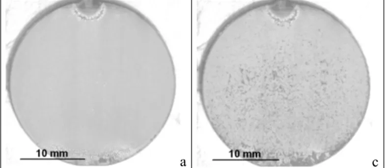
Our first objective has been to discriminate the suitable powder load content for the filling-up. First, cyclic oxidation tests have been performed on a sample with no filling-up, which is used as a reference for oxidation behavior. Figure 5 shows a damaged sol-gel thermal barrier. In opposition to damaged EB-PVD thermal barrier in which cyclic oxidation induces a non-progressive delamination of the major part of the coat, damaged sol-gel thermal barrier progressively proceeds through spallation. We can notice that the samples are more damaged on edges due to edge effects. For the filling-up of sample C containing a loaded sol at 40% of powder, damage mechanism is not the same. Indeed in figure 6, the topographies exhibit local buckling which can be due to two main reasons : first, the deposit is probably too loaded and we can see an important recovering of the upper surface of the sample. So, this impregnation is not suitable because the active matter is mainly located on the surface. The second reason is, of course, that 1150°C is probably a too high temperature to prevent from delamination, however, note that this choice has been done to accelerate the cracks network formation. According to Evans [8], observation of buckling suggests a poor adhesion between coating and substrate : cracks propagate at the interface and lead to delamination as a consequence of high stresses in the coating. Stresses resulting from the mismatch between thermal expansion coefficients of multilayers and alumina oxide. In our case, additional stresses may be due to the additional matter on the surface top during the filling-up.
a c
Figure 5. Cyclic oxidation test at 1150°C for sample without filling-up a) after 1 cycle, b) after 10 cycles
a b c
Figure 6. Cyclic oxidation test at 1100°C for filling-up sample with loaded sol of 40% of powder a) after 1 cycle, b) after 4 cycles, c) after 13 cycles
Conclusion
The research presented in the paper shows the feasibility of repairing damaged sol-gel thermal barrier coatings using dip-coating in loaded sols. Industrially, it is of utmost concern to develop repair processes as locally damaged thermal barrier coatings are usually rejected. This stands for a technical and economic viable way to increase lifetime and durability of thermal barrier coatings. Prospects are now to evaluate the interest of this filling-up process on more realistic conditions from an industrial point of view : NiPtAl substrates and less severe thermal conditions. Studies on this topic are now in progress.
References
[1] Barrow, D.A., T.E. Petroff, and M. Sayer, U.S Patent 5585136. (1996)
[2] Sniezewski, J. et al, to be published in ICMTF- International Conference on Metallurgical
Coatings and Thin Films. 2010: San Diego.
[3] Xia, C., S. Zha, W. Yang, R. Peng, D. Peng, and G. Meng: Solid State Ionics. Vol 133 (2000), p. 287-294.
[4] Viazzi, C., A. Deboni, J.Z. Ferreira, J.P. Bonino, and F. Ansart: Solid State Sciences. Vol 8 (2006), p. 1023-1028.
[5] Shane, M. and M.L. Mecartney: Journal of Materials Science. Vol 25 (1990), p. 1537-1544. [6] Fenech, J., C. Viazzi, J-P. Bonino, F. Ansart, and A. Barnabé: Ceramics International. Vol
35 (2009), p. 3427-3433.
[7] Sudhangshu, B., in High Temperature Coatings, chapter, 6, Elsevier, (2007)
[8] Evans, A.G., D.R. Mumm, J.W. Hutchinson, G.H. Meier, and F.S. Pettit: Progress in Materials Science. Vol (2000), p. 505-553.