HAL Id: hal-00598733
https://hal-mines-paristech.archives-ouvertes.fr/hal-00598733
Submitted on 7 Jun 2011HAL is a multi-disciplinary open access archive for the deposit and dissemination of sci-entific research documents, whether they are pub-lished or not. The documents may come from teaching and research institutions in France or abroad, or from public or private research centers.
L’archive ouverte pluridisciplinaire HAL, est destinée au dépôt et à la diffusion de documents scientifiques de niveau recherche, publiés ou non, émanant des établissements d’enseignement et de recherche français ou étrangers, des laboratoires publics ou privés.
Injection moulding of fibre reinforced thermoplastics:
integration of fibre orientation and mechanical
properties computations
Houssem Miled, Luisa Silva, Thierry Coupez, Jean-François Agassant
To cite this version:
Houssem Miled, Luisa Silva, Thierry Coupez, Jean-François Agassant. Injection moulding of fibre reinforced thermoplastics: integration of fibre orientation and mechanical properties computations. 27th World Congress of the Polymer Processing Society, May 2011, Marrakech, Morocco. 6 p. �hal-00598733�
Introduction
Short fibre reinforced thermoplastics are widely used for plastic part production because they can be processed with the same machines as classi-cal thermoplastics, but present enhanced me-chanical properties. Nevertheless, fibres will orient during ,for example, the mould filling process due to the rate of strain and stress history they have encountered along their flow path un-till solidification. As a consequence, fibre orien-tation will vary from one location of the injected part to another and, at a well defined position in the part, within the thickness (figure1) leading to anisotropic mechanical properties ( figure 2). This is the main limitation for the development of these reinforced materials.
Short fibres orientation has been studied for decades, both experimentally and theoretically,
Injection moulding of fibre reinforced thermoplastics:
integration of fibre orientation and mechanical properties computations
Hedi Mileda, Luisa Silvaa, Thierry Coupeza, Jean-François Agassanta * aMines-Paristech, Centre de Mise en forme des Matériaux, UMR CNRS 7635, avenue
Claude Daunesse, BP 207, 06904 Sophia Antipolis, France *Corresponding author : jean-françois.agassant@mines-paristech.fr
Abstract. Injection moulding is widely used to process short fibre reinforced thermoplastics. The quality
and especially the mechanical properties of the resulting part are linked to the mould conception (for ex-ample the gate(s) and the venting port(s) locations) and to the processing parameters which will govern fibre orientation distribution.
Fibre orientation modelling is based on the well known Folgar and Tucker equation which differ one from another by the interaction parameter, the closure approximation and by the coupling with the rheology of the reinforced melt. Quantitative comparison with experiments is very tedious and generally limited to sim-ple part geometries (plaque or disk). As a consequence, in comsim-plex geometries, fibre orientation distribu-tion is experimentally checked using several techniques and the resulting anisotropic thermomechanical properties are computed using various homogenization theories.
In this paper, we propose an integrated approach of the injection moulding of fibre reinforced thermoplas-tics starting from rheology of the material, orientation equation, interaction parameter and closure approx-imation. The resulting local fibre orientation distribution is then used in two ways in order to predict the mechanical properties of the part:
- First, using classical analytical homogenization theories but based on the computed orientation tensor and not on an experimental one,
- then, using numerical homogenization which consists in generating a Representative Elementary Volume (REV), by determining its unidirectional mechanical properties and finally, in computing directly the anisotropic properties of the part .
by numerous authors (see, for example Vincent and Agassant,1986; Bay and Tucker,1992). Fibre orientation will be described generally by a sec-ond order orientation tensor which evolution as a function of time will account for several ap-proximations: a closure approximation ( Advani and Tucker,1990), an interaction coefficient when fibre concentration increases ( Folgar and Tucker, 1984) . Rheology is modified by the presence (and the orientation) of fibres (see, for example Dinh and Armstong, 1984) but most of the au-thors decouple the flow field and the orientation field especially when complex injected parts are involved .There are many comparisons between experiments and computations in simple geome-tries (plaque, centre gated disk) but far less in in-dustrial part geometries ( Redjeb, 2007).
Fig. 1. Fibre orientation anisotropy
though the thickness of an injected part
Fig. 2. Young Modulus through the thickness
in the longitudinal and transverse directions
Tucker equation. We then apply these parameters to identify the stiffness matrix everywhere in the part and we deduce the anisotropic thermo-elas-tic properties.
Fibre orientation calculation
One assumes that the rheology of the reinforced polymer is not modified by fibre orientation. The second order orientation tensor will be influenced by the flow kinematics following Folgar and Tucker’s equation (1984):
where with Land D are respec-tively mean fibre lenght and fibre diameter, d is the spatial dimension (2 or 3) and is the sec-ond invariant of the rate of strain tensor
a4is the fourth order orientation tensor which
needs to be expressed as a function of the second orientation tensor using a closure approximation (see, for example, Advani and Tucker, 1990). In what follows we use the classical quadratic ap-proximation: a4 =a2 .a2.
When solving this equation using a standard Galerkin finite element method, one may obtain serious oscillations of the orientation tensor. Several stabilization techniques have been im-plemented , SUPG (Streamline Upwind Petrov-Galerkin Method, see Brooks et al, 1982) or RFB (Residual Free Bubbles, see Brezzi et al, 1998). Figure 3 shows that the development of orienta-tion between two parallel plates is more regular when using stabilization techniques.
In fact, polymer part producers and end-users are not especially interested in the distribution of fibre orientation but on the resulting mechanical properties and, at a first glance, by the distribu-tion of Young modulus (figure2). If they ignore fibre orientation mechanisms, they can measure this distribution (but this is a tedious task even for simple geometries), compute the resulting ori-entation tensor within the part and then develop an anisotropic thermo-elastic computation (see Advani and Tucker, 1987). The problem is to de-fine the parameters of the stiffness matrix. Gen-erally, classical composites homogenization theories have been used (see Halpin-Tsai, 1969; Eshelby,1957; Mori and Tanaka, 1973).
In this paper, we propose an unified approach of injection moulding of reinforced thermoplastics. Starting with the rheology of the reinforced ther-moplastic, the mould geometry and the process-ing conditions, we compute fibre orientation distribution in a complex part. At the same time, we build representative elementary volumes (REV) with a random orientation of the fibres in the volume and we submit these REV to several traction, compression and shear experiments in order to identify the parameters of the Advani and
SG
SG + SUP
GS + RFB
Fig.3. Comparison between
the standard Galerkin method and two stabilization methods
REM3D software with a continuous finite ele-ment approximation for the different space vari-ables, has been used (Miled, 2010). At each time step, it computes iteratively the flow and pressure fields, the temperature distribution and the orien-tation tensor. Continuous approximations allows significant reduction of the computation time when compared to the previous discontinuous approximation (Redjeb, 2007).
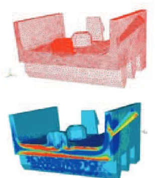
In the complex geometry presented figure 4a we illustrate at the end of the filling stage, the com-puted value of the firt component of the orienta-tion tensor (a11on figure 4b).
Thermoelastic anisotropic computation
The linear thermo-elastic constitutive equation writes:
The rigidity tensor C and the dilatation tensor α can be expressed , following Advani and Tucker (1987) , as a function of the second order and the fourth order components of the orientation tensors:
Fig. 4. Meshing of the injected part geometry (left)
and distribution of the a11component of the second order orientation tensor at the end of the filling stage (right)
The different constants biare identified with a per-fectly unidirectional composite, using for example Mori-Tanaka (1973) homogenization theory.
Knowing the modulus and the Poisson coefficient of the polymer matrix and of the fibres it is pos-sible, starting from the values of the orientation tensor at each point of the part, to derive the distribution of the Young modulus in the different dircetions(figure5).
Fig.5. Illustration of the computed Young
Modulus corresponding at one of the directionsE11
Direct numerical simulation
An alternative way to compute the anisotropic thermo-elastic properties of the part is to proceed to direct numerical simulation at the fibres level and to identify b1... b5 parameters by generating several Representative Elementary Volumes (REV) (figure6). Knowing the stiffness and the thermal dilatation tensors for fibres and matrix we derive with a mixture law the stiffness and the thermal dilatation tensors everywhere in the REV. We then apply several elastic thermo-mechanical sollicitations on this REV and we deduce nu-merically homogenised stiffness and thermal di-latation tensors.
Fig. 6. Schematic representation of a typical
The problem is to optimize the number of fibres in the REV in order to obtain a stabilized result. As an example, for unidirectional aligned fibres, we computed the E1modulus for the different REVs, varying the number of fibres and we com-pare it to the Mori-Tanaka semi analytical result (figure 7).In this case 22 fibres provide a stabi-lized result in a sufficiently refined mesh.
Fig. 7. Young modulus as a function of the
number of fibres in the REV (the Mori-Tanaka modulus is 6.21 GPa)
On each REV we know the orientation piof each fibre which allows to calculate the second and the fourth orientation tensors and we have to deduce the five biparameters. For that purpose, we sub-ject the REV to several deformations (tractions in the three directions, shear deformations in the different planes). We need to impose a minimum of five different deformations in order to deter-mine the five parameters. Here we have used six different deformations modes and we have deduced the parameters with a least square method.As an example one considers a fibre re-inforced composite with the following properties:
Tab. 1. Elastic properties of fibres and matrix
(the shape factor of the fibres is β =20 and the volume concentration is 15%)
We select several REV with different fibres orientation distributions and, for each sample we determine B = (b1,b2,b3,b4,b5) using the 6
deformation modes.
We observe discrepancies between the differentb1
values, but the order of magnitude remains iden-tical. For the following thermo-elastic computa-tions, an average of the values obtained is performed:
When increasing the number of samples, the precision of this average value will increase too.
Application to a plaque with a complex gate geometry
We apply these numerically identified values of B to a Polyarylamide plaque (Solvay IXEF 1022) which has been experimentally studied by Vincent et al., 2005) (figure 8).
Fibre shape factor β is 10, volume concentration is 31.6%, the interaction coefficient in Folgar and
Tucker equation is C1=10-2. The viscosity of the
reinforced thermoplastic follows a Carreau law (see Vincent et al, 2005).
The processing parameters are the followings: injection rate of 15 cm3/s injection temperature
of 270°C, mould temperature of 130°C.
Fig. 8. Geometry of the plaque in the complex
geometry case test
The geometry of the inlet gate is quite complex. (figure 9)
Fig. 9. Gate geometry
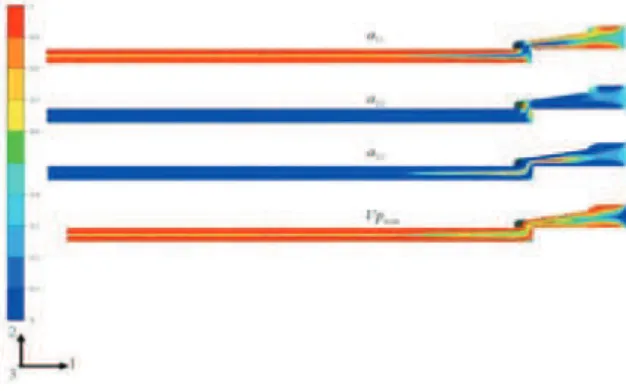
Figure 10 presents the different components of the second order orientation tensor obtained at the end of the injection moulding computation
Fig. 10. Distribution near the gate of the different
components of the second order orientation ten-sor, as well as the main eigenvalue of this tensor
These numerical results are compared to experimental measurements of fibre orientation (figure 11).
Fig. 11. Comparison of numerical computation
of the a11 component of the orientation tensor
(continuous approaches and discontinuous approaches) and experiments
Using the biparameters identified enough direct
numerical simulation in the preceding section (mean values) we determine the different com-ponents of the Young modulus. One observes, figure 10 that fibres are oriented in the flow di-rection near the mould wall (i.e. along the plaque surface) which induces a value of the Young modulusE11 which is very near the value of the
longitudinal Young modulus for a transverse isotropic composite. The minimum value ofE11is
in the centre of the plaque where fibres are mostly oriented in the transverse direction. The Young modulusE22andE33are much lower, which
means that the plaque is more rigid in direction 1 than in directions 2 and 3.
Fig. 12. Distribution of the anisotropic Young
modulus (GPa)
The plaque is set in on the gate side and subjected to a simple traction in direction 1 (figure 13) at its extremity. Using the thermo-elastic computation we are able to compute the plaque deformation everywhere. On figure 13, we compare the
dis-Bibliography
S.G.Advani and C.L.Tucker, Journal of Rheology
31, 751-784 (1987)
S.G.Advani and C.L.TuckerIII, Journal of
Rheology,34, 367 (1990)
R.S.Bay and C.L.Tucker III, Polymer
composite 13, 332-341 ( 1992)
F.Brezzi, L.P.Franca and A.Russo, Computer
methods in applied Mechanics 166, 25-33
(1998)
A.N.Brooks and T.F.R.Hughes, Computer methods in applied Mechanics and Engineering
32, 199-259 (1982)
S.M.Dinh and R.C.Amstrong, Journal of Rheology 28,207- (1984)
J.D.Eshelby, Proceeding of the Royal Society A
241,376-396 (1957)
F.Folgar and C.L.Tucker III,Journal of Reinforced Plastics and Composites 3,98-119 (
1984)
J.C.Halpin, Journal of Composites Materials 3, 732-734 (1969)
H.Miled, Modélisation de l’orientation de fibres
induite par l’écoulement et comportement thermo-elastique anisotrope à l’état solide, Thèse
de Doctorat, Ecole des Mines de Paris (2010) T.Mori and K.Tanaka, Acta Metal 21, 571-574 (1973)
A.Redjeb, Simulation numérique de l’orientation
de fibres en injection de thermoplastiques ren-forcés, Thèse de Doctorat, Ecole des Mines de
Paris (2007)
M.Vincent and J.F.Agassant, Polymer Composite 7,73-83 (1986)
M.Vincent, T.Giroud, A.Clarke and C.Eberhardt,
Polymer 46, 6719-6725 (2005)
placement in direction 1 on the mid-plane of the plaque for an heterogeneous fibre orientation and for an isotropic fibre orientation (all the components of the Young modulus are then identical). We ob-serve that the displacement is divided by a factor 2 when accounting for an anisotropic fibre distribution.
Fig. 13. u1component of the displacement;
com-parison between an isotropic and an anisotropic fibre orientation
Conclusion
This paper represents a first attempt to connect mould filling computation, resulting short fibre ori-entation, determination of the elasticity and dilata-tion tensors using direct numerical simuladilata-tion, and resulting thermo-elastic properties. Measuring the distribution of fibre orientation, even in a simple plaque, is a tedious task as measuring plaque dis-placements when subjected to various solicitations is common and of easy practice. If confident, this kind of approach may significantly simplify gate positioning and injection moulding parameters optimization for target mechanical properties. Nevertheless, the method needs to be improved at different levels: improvement of Folgar and Tucker equation in order to better account for fibre/fibre in-teraction and fibre/mould wall inin-teraction, choose of appropriate closure approximations, optimization of REV ( Representative Elementary Volumes) , im-provement of the number of applied mechanical so-licitations and of the optimization method for the