HAL Id: hal-03052719
https://hal.archives-ouvertes.fr/hal-03052719
Submitted on 10 Dec 2020HAL is a multi-disciplinary open access
archive for the deposit and dissemination of sci-entific research documents, whether they are pub-lished or not. The documents may come from teaching and research institutions in France or abroad, or from public or private research centers.
L’archive ouverte pluridisciplinaire HAL, est destinée au dépôt et à la diffusion de documents scientifiques de niveau recherche, publiés ou non, émanant des établissements d’enseignement et de recherche français ou étrangers, des laboratoires publics ou privés.
Dual-Cation Electrolytes for High-Power and
High-Energy LTO//AC Hybrid Capacitors
Yu Chikaoka, Etsuro Iwama, Tsukasa Ueda, Natsuki Miyashita, Shinichi Seto,
Masato Sakurai, Wako Naoi, Mcmahon Thomas Homer Reid, Patrice Simon,
Katsuhiko Naoi
To cite this version:
Yu Chikaoka, Etsuro Iwama, Tsukasa Ueda, Natsuki Miyashita, Shinichi Seto, et al.. Dual-Cation Electrolytes for High-Power and High-Energy LTO//AC Hybrid Capacitors. Journal of Physical Chemistry C, American Chemical Society, 2020, 124 (23), pp.12230-12238. �10.1021/acs.jpcc.0c01916�. �hal-03052719�
OATAO is an open access repository that collects the work of Toulouse
researchers and makes it freely available over the web where possible
Any correspondence concerning this service should be sent
to the repository administrator:
tech-oatao@listes-diff.inp-toulouse.fr
This is a publisher’s version published in:
https://oatao.univ-toulouse.fr/
27022
To cite this version:
Chikaoka, Yu and Iwama, Etsuro and Ueda, Tsukasa and Miyashita, Natsuki and Seto, Shinichi and Sakurai, Masato and Naoi, Wako and Reid, McMahon Thomas Homer and Simon, Patrice and Naoi, Katsuhiko Dual-Cation Electrolytes for
High-Power and High-Energy LTO//AC Hybrid Capacitors. (2020) Journal of
Physical Chemistry C, 124 (23). 12230-12238. ISSN 1932-7447 .
Official URL:
https://doi.org/10.1021/acs.jpcc.0c01916
Dual-Cation Electrolytes for High-Power and High-Energy LTO//AC
Hybrid Capacitors
Yu Chikaoka, Etsuro Iwama,
*
Tsukasa Ueda, Natsuki Miyashita, Shinichi Seto, Masato Sakurai,
Wako Naoi, McMahon Thomas Homer Reid, Patrice Simon, and Katsuhiko Naoi
*
Cite This:J. Phys. Chem. C 2020, 124, 12230−12238 Read Online
ACCESS
Metrics & More Article Recommendations*
sı Supporting InformationABSTRACT: Dual-cation electrolyte systems, which contain two cations [Li+ and spiro-1,1′-bipyrrolidinium (SBP+), are proposed to enhance the power capability of hybrid capacitors composed of thick Li4Ti5O12(LTO) negative (200 μm) and activated carbon (AC) positive electrodes (400 μm), which thus reduces the resistive overvoltage in the system. Detailed studies of the mass transport properties based on the combination of spectroscopy and electrochemical analysis have shown that the presence of SBP+, despite slower Li+ transport in the electrolyte bulk, further reduces overvoltage associated with migration limitation in the thick LTO electrode macropores. This study on the dual-cation electrolyte quantifies the influence of the addition of a supporting electrolyte and shows interest in SBPBF4addition for increasing the output power density of hybrid capacitors with a thick electrode configuration.
1. INTRODUCTION
Electric double layer capacitors (EDLCs), also known as supercapacitors, are energy-storage devices (ESDs) boasting speeds and lifespans far greater than those of batteries, but whose practical applications are limited by their moderate energy densities. This has motivated intense efforts to improve the storage capacity of EDLCs.1,2 Although conventional EDLCs are symmetric devices that consist of two identical activated-carbon (AC) electrodes, much recent research has focused on asymmetric/hybrid supercapacitors that pair an AC positive electrode with a high-capacity faradaic negative electrode made from a lithium intercalation compound such as Li4Ti5O12 (LTO).3,4 The adoption of hybrid structures succeeds in increasing the energy density.5,6Besides designing another EES device system such as dual-ion batteries, which apply anion-intercalation into carbon positive electrodes,7,8 further enhancement can be expected by simply increasing electrode thickness from a few tens to hundreds of micro-meters. However, the use of such thick electrodes is detrimental to the power capability with an increase in ionic resistance of the electrodes.9,10Furthermore, the limited choice of electrolytic salts available for hybrid capacitors made the situation ever more complex. Ideally, one would like to use LiPF6, the electrolyte most commonly used in Li-ion batteries (LIBs), but this is incompatible with the choice of AC as an electrode material, as LiPF6 is unstable against the moisture coming from AC. Instead, supercapacitors with AC electrodes must use alternative electrolytes, such as LiBF4,3,4,11 whose ionic conductivity is less than LiPF6, and the search for
high-conductivity supercapacitor electrolytes is the focus of intense research efforts.
One of the developed approaches to improve the rate capability of LIBs is to enhance the Li+ transport (diffusion, migration) by using alternative lithium electrolytic salts or solvents.12 Among them, the superconcentrated lithium-salt electrolyte, generally dissolving over 4−5 M of electrolytic salts, is a topic that has been intensively researched recently to improve power performances as well as the potential window of electrolytes.13,14 Such superconcentrated electrolytes are reported to suppress the concentration polarization thanks to the improvement of Li+transport.13,14
Using thick electrodes, however, their low ionic conductivity may be detrimental to the power performances, while several issues are expected for their practical applications, such as difficulty in the electrolyte injection process due to their very high viscosity.15 In this Article, we develop an alternative route through the addition of a supporting electrolyte to increase the ionic transport properties, mainly aimed at ESDs using thick electrodes. LTO//AC hybrid capacitors with a total electrode thickness of 600 μm were assembled and tested in electrolyte containing various amounts of a supporting electrolyte, and the rate Received: March 6, 2020
Revised: May 11, 2020 Published: May 19, 2020
Article
pubs.acs.org/JPCC
© 2020 American Chemical Society
12230
https://dx.doi.org/10.1021/acs.jpcc.0c01916
J. Phys. Chem. C 2020, 124, 12230−12238
This is an open access article published under an ACS AuthorChoice License, which permits copying and redistribution of the article or any adaptations for non-commercial purposes.
performance was investigated in detail. Spiro-1,1 ′-bipyrrolidi-nium tetrafluoroborate (SBPBF4) was selected as a supporting electrolytic salt thanks to its high ionic dissociation to be added into LiBF4-based electrolytes. We evidenced that the presence of a supporting SBPBF4electrolyte significantly improved the electrochemical performance of hybrid capacitors using a few-100 μm-thick LTO electrodes despite the decrease in Li+ transport number. We expect that ourfinding may offer flexible choices in electrolyte composition, especially in case of using thick electrodes attaining both high power and energy density of ESDs.
2. EXPERIMENTS
2.1. Electrolyte Preparation. Electrolytes (water content < 20 ppm) were prepared by dissolving 1 M lithium tetrafluoroborate (battery grade LiBF4, Kishida Chemicals, Japan) and x M spiro-1,1′-bipyrrolidinium tetrafluoroborate (SBPBF4, Japan Carlit, 0 < x < 3) in propylene carbonate (PC, battery grade, Kishida Chemicals, Japan). Prior to use, prepared electrolytes were stirred under an Ar-filled glove box (UNICO) overnight.
2.2. Physicochemical Properties of Electrolytes. Ionic conductivity of the electrolytes was measured using a conductivity meter setup (Mettler Toledo, S230) with a four-electrode Pt conductivity sensor (Mettler Toledo, InLab 710) at T = 25 °C. The viscosity of the electrolytes was measured using a digital viscometer (Brookfield, DV-II+pro). All of the viscosity measurements were conducted at T = 25 °C. The volume of electrolytes was set to be 1 mL, and the dynamic viscosity was calculated from the obtained shear stress
at the shear rate where the spindle experienced 10% of the maximum torque of the equipment.
2.3. Self-Diffusion Coefficients of Electrolytes. Self-diffusion coefficients of electrolytes were measured by pulsed-gradient spin−echo nuclear magnetic resonance (PGSE-NMR), with a 400 MHz NMR spectrometer (JEOL, JNM-ECZR) equipped with JEOL gradient probes at room temperature (T = 25 °C). Self-diffusion coefficients D were calculated according toeq 1.16
γ δ δ
= − Δ −
S S g D
ln( / )0 2 2 2 ( /3) (1)
Here, S/S0 [−] is the echo attenuation, γ [s−1 T−1] is the gyromagnetic field, g [T m−1] is the strength, δ [s] is the duration of the gradient pulse, and Δ [s] is the interval between the gradient pulse. Each NMR microtube (ϕ = 5 mm, Shigemi) was filled with prepared electrolytes (about 5 mm height, 70 μL) and sealed in the dry room before any measurements. PGSE-NMR measurements were performed by applying a magneticfield gradient pulse from 1.0 to 13.5 T m−1 with a 50 ms interval between each gradient pulse. Self-diffusion coefficients of Li+(7Li), SBP+(1H), and BF
4−(19F) in electrolytes were calculated from the obtained slopes of the intensity against the magneticfield gradient strength.
2.4. Electrode Preparation. Li4Ti5O12 (LTO, Toho Titanium) and activated carbon (AC, YP-50F, Kuraray) were used as positive and negative active material electrodes, respectively. Previous experiments by our group17 have shown that an LTO//AC mass ratio of 0.79 (=exhibited capacity ratio of 3.5) resulted in optimized performance of the cell, corresponding to electrode loading mass/thickness of 13.3
Figure 1.Schematic illustrations of cell configurations prepared in this work: (a) two-electrode cells (coin type for charge−discharge test), (b) three-electrode cells (laminate type for charge−discharge test), (c) three-electrode cells (flat type for CV), and (d) four-electrode cells (laminate type for EIS).
The Journal of Physical Chemistry C pubs.acs.org/JPCC Article
https://dx.doi.org/10.1021/acs.jpcc.0c01916
J. Phys. Chem. C 2020, 124, 12230−12238
mg cm−2/200 μm (LTO) and 16.8 mg cm−2/400μm (AC). The total electrode thickness of LTO and AC electrodes (ϕ = 16 mm) was set to be 600μm, with the aim to maximize the energy density for 2032 coin-type cells. Each active material was mixed with 10 wt % of Ketjen Black conducting additive (KB, ECD-600JD, Ketjen Black International) and 10 wt % of polytetrafluoroethylene binder (PTFE, Du Pont-Mitsui Fluo-rochemicals Co.), and then roll-pressed to make electrodes with fixed thickness and density (400 ± 10 μm and 0.41 g cm−3for AC, 200± 10 μm and 0.68 g cm−3for LTO). LTO and AC electrodes were dried at 200°C under vacuum (<−0.1 MPa) overnight and were further pasted in dry room on current collectors using Hitasol AB-1 (Hitachi Chemical) as a conductive adhesive to prepare the electrodes. Two different current collectors were selected for different types of cells (see section 2.5): stainless steel (SUS316L, 1 mm thick) for 2032 coin-type andflat-type cells, and etched aluminum foil (40 μm thick) for laminated-type cells. Prepared electrodes were then dried at 200°C under vacuum (<−0.1 MPa) overnight before cell assembly. For cyclic voltammetry (CV) analysis, thin LTO electrodes with a loading of 1.23 mg cm−2were prepared by coating LTO slurry on an etched aluminum foil (20μm thick). 80 wt % of LTO powders, 10 wt % of KB as conductive agent, and 10 wt % of polyvinylidenefluoride (PVDF) binder were all dissolved in 1-methyl-2-pyrrolidone (NMP) to prepare the slurry.
2.5. Cell Assembly and Electrochemical Character-ization. For electrochemical characterization, we used four different cell designs shown in Figure 1a−d. 2032 coin-type cells (Figure 1a) were assembled to achieve charge/discharge experiments of LTO//AC hybrid capacitor cells. After being dried overnight, electrodes and cellulose separator (35 μm thickness with 75% of porosity,18 Nippon Kodoshi (NKK)) were soaked in electrolytes and then put under a vacuum (−70 kPa) for 10 min to ensure electrolyte impregnation. The wet separator then was sandwiched by LTO and AC electrodes, placed into stainless cell cases, and sealed to obtain hybrid capacitor coin cells. Constant current (CC) charge−discharge cycles were achieved within the voltage range of 0−3.0 V by potentiostat units (HJ 1001 SD 8, Hokuto). All of the cells were placed in a climatic chamber to keep T = 25 °C. The discharge current densities ranged from 1 to 100 mA cm−2, while the applied charge current was kept constant at 1 mA cm−2. Prior to any tests, cells were precycled two times at a slow current density of 0.1 mA cm−2within a 0−3.0 V voltage window.
The three-electrode laminate-type cells (5 cm × 11 cm, Figure 1b) were assembled by following the same procedure as was used for the 2032 coin-type cells, with the addition of a lithium metal reference electrode, to track the potential of
negative LTO and positive AC electrodes separately during LTO//AC hybrid cells’ operation. A small piece of lithium metal was added as a reference electrode, and LTO and AC electrodes (2 cm× 4 cm) were pasted on an etched aluminum foil (40 μm thick). Assembled cells were charged and discharged at the same conditions as those applied for the coin-type cells.
For CV analysis on LTO electrode, we assembled three-electrodeflat-type cells (Figure 1c) using 10 μm-thick LTO working, 200 μm-thick LTO counter, and lithium metal electrodes. Here, we chose the overcapacitive 200 μm-thick LTO electrode as the counter, which was Li predoped in use, to exclude any influence of AC positive electrode. CV measurements (VersaSTAT 3, AMETEK) were conducted at different scan rates from 0.278 to 278 mV s−1, so that scan times changed from 7200 s (corresponding to 0.5C) to 7.2 s (500C).
EIS measurements were performed on LTO//LTO symmetric laminate-type cells (Figure 1d), to evaluate the ionic and charge-transfer resistance of the LTO electrodes. The details for the cell preparation are described inFigure S1. In the LTO//LTO symmetric cells, two LTO electrodes (200μm thick and 4 cm2each, working electrodes 1 and 2) were placed in the center and sandwiched between a cellulose separator, while two AC electrodes (400 μm thick and 4 cm2 each, counter electrodes 1 and 2) were respectively placed in the upper and lower parts of the LTO electrodes. Such a cell configuration allows us to switch two different measurement modes by just changing the connection of the cable: (i) charge and discharge mode [state of charge (SOC) control of LTO] in LTO//AC hybrid capacitor configuration with series-connected two LTO and two AC, respectively, and (ii) EIS measurement mode in LTO//LTO symmetric configuration using only two LTO electrodes with the same SOC condition. The merit of our cell configuration is that there is no need to disassemble the cells prior to EIS measurements unlike in previously reported symmetric cell configurations. For the measurements,first, cells were precycled in LTO//AC hybrid capacitor mode for 2 cycles between 0 and 3.0 V at constant-current (CC) charge (0.1 mA cm−2) and CC discharge (0.1 mA cm−2) mode. The cells then were charged to 2.7 V at constant-current and constant-voltage (CC−CV) mode with a current density of 0.1 mA cm−2, and the potential was held during 12 h at 2.7 V. EIS measurements using LTO//LTO symmetric cells were carried out at OCV (fully discharged state) and 1.55 V vs Li/Li+ atfive different temperatures (25, 30, 35, 40, and 45°C), using a perturbation signal of ±10 mV within a frequency range from 0.01 Hz to 65.5 kHz. The generalized finite length Warburg element short-circuit Table 1. Measured Values of Ionic Conductivity, Viscosity, and Self-Diffusion Coefficient for Single- and Dual-Cation Electrolytes of Various Additive Concentrationsa
self-diffusion coefficient/
10−10m2s−1 transport number/− conductivity/mS cmindividual ionic −1
ionic conductivity/mS cm−1 viscosity/cP Li+ SBP+ BF
4− Li+ SBP+ BF4− Li+ SBP+ BF4−
1 M LiBF4/PC 3.57 6.77 0.88 1.26 0.41 0.59 1.47 2.10
1 M LiBF4+ 1 M SBPBF4/PC 5.89 11.35 0.56 1.03 0.92 0.16 0.30 0.54 0.96 1.77 3.15
1 M LiBF4+ 2 M SBPBF4/PC 7.79 18.41 0.30 0.62 0.52 0.10 0.40 0.50 0.76 3.12 3.91
1 M LiBF4+ 3 M SBPBF4/PC 7.36 30.65 0.16 0.35 0.30 0.07 0.43 0.50 0.49 3.19 3.68 aIn this table,“ionic conductivity” refers to the measured ionic conductivity of the electrolytic solution, while “individual ionic conductivity” refers
to the ionic conductivity times the transport number.
The Journal of Physical Chemistry C pubs.acs.org/JPCC Article
https://dx.doi.org/10.1021/acs.jpcc.0c01916
J. Phys. Chem. C 2020, 124, 12230−12238
terminus (Ws) was used forfitting of impedance spectra at the SOC of 25%.8
3. RESULTS AND DISCUSSION
3.1. Physical Properties of Single- and Dual-Cation Electrolytes.Table 1lists the ionic conductivity and viscosity of LiBF4 (single-cation) electrolytes with various concen-trations of SBPBF4 (dual-cation electrolytes), as well as self-diffusion coefficients, transport numbers, and ionic conductiv-ities of ions. The whole ionic conductivity increases significantly as the SBPBF4 concentration increases to 2 M and then further reaches a plateau. The viscosity of the dual-cation electrolytic solutions is 2−4 times greater than that in the single-cation electrolyte. The diffusion coefficients of all ionic species (Li+, BF4−, and SBP+) decrease with increasing SBPBF4concentration. Also, the diffusion coefficient of SBP+ exceeds that of Li+ at all SBPBF4 concentrations; this is assumed to originate from the smaller ionic radius of SBP+as compared to that of solvated Li+.
Transport numbers tx for ion species (x = Li+, SBP+, and BF4−) were calculated fromeq 2:16
= [ ] [ ] + [ ] [ ] + [ ] [ ] + + − − + + t N D N D N D N D /( Li Li BF BF SBP SBP ) x x x 4 4 (2)
Here, Nxand Dxare respectively the number of carrier and the self-diffusion coefficient for ion species x (x = Li+, SBP+, and BF4−). Practically, because the number of each carrier, Li+, SBP+, and BF4−, cannot be estimated within a dual-cation electrolyte, Nxof each carrier was determined from the original concentration of the prepared electrolytes. As the SBPBF4 concentration increases, the transport number of Li+decreases, while that of SBP+increases. Ionic conductivities of the three ionic speciesσx(x = Li+, SBP+, and BF
4−) were calculated from eq 3:
σx =σEIS×tx (3)
As the SBPBF4 concentration increases, both the transport number and the ionic conductivity of Li+ decrease, indicating reduced conductivity of Li+ in the bulk electrolytic solution,
while both parameters of SBP+ increase and are superior to those of Li+. By addition of 2 M SBPBF4, the contribution of SBP+and BF4−to the total ionic conductivity reaches 90%.
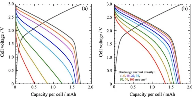
3.2. Performance Tests for Two-Electrode Cells.Figure 2 shows the experimental charge−discharge curves for the hybrid capacitors assembled with 200μm-thick LTO negative and 400μm-thick AC positive electrodes using single-cation (1 M LiBF4/PC) and dual-cation (1 M LiBF4 + 2 M SBPBF4/ PC) electrolytes. The discharge curves at 1 mA cm−2for both electrolytes exhibit a sloping profile, as a result of the combination of a constant potential discharge (LTO negative electrode) and a capacitive sloping signature (AC positive electrode). At higher discharge currents (>20 mA cm−2), the mean discharge voltages for the dual-cation electrolyte are much higher as compared to those for the conventional single-cation electrolyte. Note that the added SBPBF4concentration in this study was fixed at 2 M after the dependency of cell power performances on the SBPBF4concentration from 0 to 3 M added in 1 M LiBF4/PC was examined (see Figure S2).
The smaller polarization observed for the dual-cation electrolyte shows evidence of improved transport properties (decreased ohmic drop) and/or improved electrochemical reaction kinetics. Both the IR drop, due to bulk electrolyte resistance, and the polarization in the thick electrode are significantly smaller when the dual-cation electrolyte is used. These results are supported by the change of the rate-capability on the electrode thickness (see Figure S3a−c). As shown in Figure S3a, for thin electrodes (LTO = 40μm, AC = 80 μm), no difference in rate capability was observed for the electrolytes with or without SBPBF4. The thicker were the electrodes (Figure S3b,c), the greater was the difference between the two electrolytes: for thicker electrodes (400 μm-thick LTO), 70% of the capacity was maintained at 3.3 mA g−1 in the dual-cation electrolyte, while the capacity was null for the single-cation reference cell. From the above findings, the use of dual-cation electrolytes results in significant improve-ments in cell performance due to a drastic decrease of the electrode polarization. For example, at a current density of 100 mA cm−2, the single-cation capacity retention was 30% at 1 mA cm−2, as compared to 78% for the dual-cation system.
Figure 2.Results of performance tests for two-electrode cells: (a) single-cation (1 M LiBF4/PC) or (b) dual-cation (1 M LiBF4+ 2 M SBPBF4/ PC) electrolytes at discharge current densities ranging from 1 to 100 mA cm−2.
The Journal of Physical Chemistry C pubs.acs.org/JPCC Article
https://dx.doi.org/10.1021/acs.jpcc.0c01916
J. Phys. Chem. C 2020, 124, 12230−12238
3.3. Performance Tests for Three-Electrode Cells. Three-electrode experiments were achieved to study the electrochemical behavior of each electrode separately. Figure 3 compares the experimental discharge curves obtained in single-cation and dual-cation electrolytes. The discharge capacity is normalized to the capacity measured at 0.1 mA cm−2discharge current density. First, potential drops observed when switching on the current (IR drops) are reduced in the dual-cation system for both AC positive and LTO negative electrodes. The capacitance of the AC positive electrode was calculated from the slopes of the discharge curves and plotted versus the discharge current (Figure 3c, upper part). As can be seen from the figure, there is no difference in calculated capacitances between the two electrolytes, indicating that the kinetics of ion adsorption/desorption at the surface of the AC
electrode is kept the same. Differently, three-electrode measurements show that the polarization at the LTO negative electrode is greatly decreased in the dual-cation electrolyte at high current density, as can be seen inFigure 3c (lower part). To clearly understand the origin of such a polarization decrease on the LTO electrode, dedicated electrochemical measurements such as CV and EIS were conducted, and the results are shown in the following sections.
3.4. CV Measurements.Figure 4a shows CVs of the LTO negative electrode at different potential scan rates. CV experiments were recorded at potential scan rates from 0.278 to 278 mV s−1, so that scan times changed from 7200 s (0.5C) to 7.2 s (500C). At a slow scan rate (0.278 mV s−1; 0.5C), we observe the typical electrochemical behavior for the LTO electrode in both single- and dual-cation electrolytes, showing
Figure 3.Discharge curves for three-electrode cells with electrolytes of (a) single-cation (1 M LiBF4/PC) or (b) dual-cation (1 M LiBF4+ 2 M SBPBF4/PC) electrolytes at discharge current densities ranging from 0.1 to 30 mA cm−2. The horizontal axis is normalized to a capacity of 0.1 mA cm−2to clarify the comparison of polarization behavior. (c) Static capacitance on the AC positive electrode side, and polarization of the LTO negative electrode side, versus discharge current density. LTO polarization corresponds to the difference in LTO potential at SOC 50% at between 0.1 mA cm−2and a given current density. Estimated values were normalized by subtracting IR drops.
Figure 4.(a) Cyclic voltammograms of LTO for single-cation (1 M LiBF4/PC) and dual-cation (1 M LiBF4+ 2 M SBPBF4/PC) electrolytes at different scan rates from 0.278 to 278 mV s−1(0.5−500C). (b) Plots of peak oxidation current versus scan rate and obtained b factor for the two electrolyte systems. TheΔC corresponds to the region where linearity can be seen for two electrolytes, extracted from the original plots shown in
Figure S4.
The Journal of Physical Chemistry C pubs.acs.org/JPCC Article
https://dx.doi.org/10.1021/acs.jpcc.0c01916
J. Phys. Chem. C 2020, 124, 12230−12238
similar capacity values of ca. 170 mAh g−1. Differently, at fast scan rates (16.8−278 mV s−1; 30−500C), a distorted electrochemical signature was obtained, together with peak potential shifts for the single-cation system, which was reduced for the dual-cation cell.Figure S4plots the difference between the peak potentials versus the scan rate. At slow scan rates (0.278−11.1 mV s−1; 0.5−20C), the plots for the single- and dual-cation systems are similar. At high potential scan rates (16.8−278 mV s−1), however, the plot for the single-cation system is much steeper than that for the dual-cation case, thus evidencing a change in the electrochemical behavior.
Figure 4b shows the change of the oxidation peak current of LTO versus the scan rate (up to 11.1 mV s−1), which can be expressed aseqs 4and5:
=
Ip avb (4)
= +
I a b v
log p log log (5)
where v is the scan rate, a is a constant that includes the diffusion coefficient, and b is a dimensionless constant taking values in the range 0.5−1. A b value close to 0.5 shows a diffusion-limited process, that is, a limitation by the diffusion of Li+in the solid LTO, while values close to 1 correspond to a nondiffusion limited, surface-like redox process.19For potential scan rates below 16.8 mV s−1, similar b values, close to 0.5, were found for the LTO electrode in both electrolytes, without a significant difference in vertical offset. This means that the solid-state diffusion of Li+does not differ significantly between the two electrolytes, and thus the LTO reaction kinetics are limited by the solid diffusion of Li+. In contrast, at higher potential scan rates (>16.8 mV s−1,Figure S4), the behavior of the two systems differs significantly: the growth of the overvoltage magnitude with a scan rate becomes exponential in the single-cation case, but remains only linear in the dual-cation case. The different behaviors of the single- and dual-cation electrolytes may then be attributed to the Li+transport (migration) of the electrolyte in the LTO electrode.
3.5. Impedance Measurements for Symmetric Cells. Electrochemical impedance spectroscopy (EIS) experiments have been achieved to obtain further detailed insights on the transport versus kinetic limitations. LTO//LTO symmetric cells (Figure 1d) were applied for EIS experiments, to focus on the LTO electrode resistances, which can be divided into two
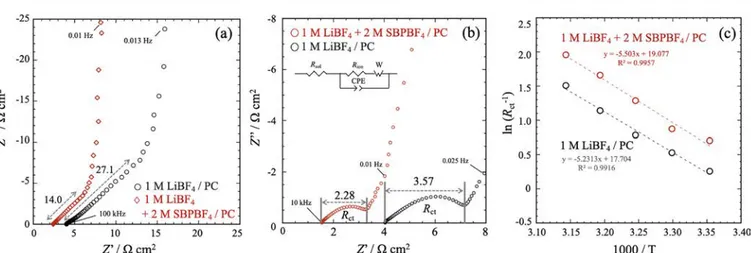
main contributions: the electrolyte ionic resistance within electrode macropores (Rion) and the Li+ charge-transfer resistance at the electrode/electrolyte interface (Rct). Note that assembled LTO//LTO symmetric cells were accustomed to easily switch measurement modes between LTO//AC hybrid capacitor cell cycling (SOC control of LTO) and EIS on LTO//LTO symmetric cells without any disassembling of the cells (seeExperiments and Figure S1). Prior to any EIS measurements, all of the cells were precycled (two cycles) in the LTO//AC hybrid capacitor connection mode between 0.0 and 3.0 V. EIS measurements then were conducted using the LTO//LTO symmetric design in both the delithiated (SOC of LTO = 0%, 0 V in LTO//AC) and the lithiated (SOC = 25%, 2.7 V in LTO//AC) states.Figure 5a shows the EIS spectra of LTO//LTO symmetric cells in the delithiated state (SOC = 0%). The Rionmeasured at high frequency at the intercept of the plot on the real axis20for the dual-cation electrolyte (Rion: 14.0Ω cm2) is about 2 times less as compared to the single-cation electrolyte (Rion: 27.1Ω cm2), which well agrees with the difference in conductivity between two electrolytes. No high frequency loop related to the SEI layer formation on the LTO surface can be observed, and the plot corresponds to a blocking porous electrode behavior in the absence of Li+ reaction. Figure 5b shows the EIS spectra conducted on LTO//LTO symmetric cells at the lithiated state (SOC = 25%). A semicircle can be seen in Figure 5b, which corresponds to the Rct.21 The value of the Rct was estimated by an equivalent circuit given in the inset of thefigure. Overall, the Rctvalues for the LTO negative electrode for both of the electrolytes were 6−7 times smaller as compared to the Rion values. The obtained results well agree with the previous report10that shows that the main contribution to the electrode resistance changes from Rctfor thin-film electrodes to Rion for thick-film electrodes. This is further supported by the fact that, using thin-film electrodes (LTO, 40 μm; AC, 80 μm), the high conductivity of the dual-cation electrolyte does not make a major difference in the discharge characteristic (Figure S3). The Rct then was found to be lower in the dual-cation electrolyte (Rct: 2.28 Ω cm2) than in the single-electrolyte system (Rct: 3.57 Ω cm2), indicating faster electrochemical kinetics. The activation energy Eaof the reaction at the LTO negative electrode was calculated usingeq 6:22
= − · +
R E R T A
ln(1/ ct) a/ 1/ ln 0 (6)
Figure 5.EIS spectra using LTO//LTO symmetric cells for single-cation (1 M LiBF4/PC) and dual-cation (1 M LiBF4+ 2 M SBPBF4/PC) electrolytes (a) when delithiated (SOC of LTO = 0%, 0 V vs Li/Li+in LTO//AC) and (b) when lithiated (SOC = 25%, 2.7 V vs Li/Li+in LTO// AC). (c) Arrhenius plot of the charge-transfer resistance Rctobserved in the EIS spectra shown in (b).
The Journal of Physical Chemistry C pubs.acs.org/JPCC Article
https://dx.doi.org/10.1021/acs.jpcc.0c01916
J. Phys. Chem. C 2020, 124, 12230−12238
where R is the gas constant, T is the absolute temperature, and A0 is the pre-exponential factor, which is a temperature-independent constant. The change of ln(1/Rct) versus 1/T, plotted in semilog scale in Figure 5c, shows nearly identical slopes but with constant offset, suggesting nearly equal activation energies Eabut significantly different pre-exponential factors A0for the two electrolytes.
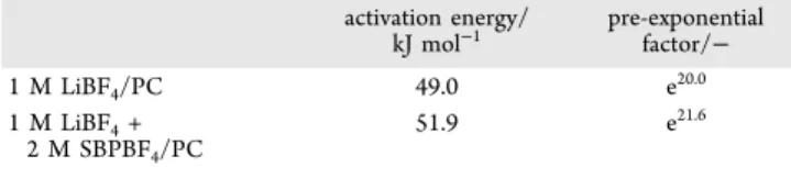
Table 2 lists the activation energies Ea and pre-exponential factors A0calculated from the Arrhenius plots (eq 6). Indeed,
no significant difference in Ea is observed between the two electrolytes; the obtained values are consistent with previous works reporting an activation energy Eaof approximately 50 kJ mol−1 for reactions at LTO negative electrode using 1 M LiPF6/EC + DMC as the electrolyte.23,24This result indicates that the solvation shells of Li+ are more or less the same with and without SBPBF4, showing that the supporting electrolyte does not change the kinetics of Li+intercalation itself. Raman (Figure S5) and NMR (Figure S6) spectroscopies further support the fact that no drastic change of solvation structure was observed following the addition of SBPBF4 to the electrolyte. However, the pre-exponential factor A0increased with an addition of SBPBF4by a factor of 4.95 from e20to e21.6. To clarify this, we have considered several hypotheses (ionic charge carriers, number of active sites, SEI layer, and ionic conductivity), and, among them, we concluded that the ionic conductivity is responsible for the increase in pre-exponential factor based on the following discussion.
Ionic Charge Carriers. The ionic charge carriers density, that is, dissociated Li+ concentration, affects the pre-exponential factor; the higher is the concentration of Li+, the higher is A0.
25
The apparent degree of dissociation of the various electrolytes, Haven ratio (HR), was calculated on the basis of the molar ionic conductivity obtained by EIS and NMR (see Supporting Information [Haven ratio]).26 As shown in Table 3, the HR of the dual-cation electrolyte decreases with the addition of SBPBF4. Considering the fact that the molar concentration of Li+ isfixed at 1.0 M for all electrolyte compositions, the dissociation degree of Li+ decreases with increasing SBPBF4 concentration. So, the
number of Li+ carriers cannot be the origin of the increased pre-exponential factor observed for this system, and we have to determine another reason for why the pre-exponential factor increased.
Number of Active Sites. The number of active sites that can intercalate and deintercalate27 Li+ ions has a direct influence on the pre-exponential factor. However, because our experi-ments use the same LTO electrodes for both the single- and the dual-cation systems, the number of active sites is presumably identical in the two systems.
SEI Layer. The charge-transfer resistance is affected by the formation of SEIfilms.28To see whether any SEIfilms formed in a dual-cation system affected the EIS spectra, we compared EIS spectra on LTO//LTO symmetric cells before and after exchanging electrolytes between single-cation and dual-cation electrolyte systems (Figure S7). The obtained EIS spectra were almost identical for both electrolytes. Thus, the presence of SEI film cannot explain the difference in the pre-exponential factor.
Ionic Conductivity. From above, the increase of the pre-exponential factor observed in the presence of the dual-cation electrolyte cannot be ascribed to a difference in Li+ carrier numbers, active sites, or SEI layer. In contrast, the ionic conductivity does change a lot, suggesting that this phenomenon is responsible for the change in pre-exponential factors. Such an increase of the A0 suggests an increased Li+ concentration available at the LTO surface.
To pursue this notion, we note that reversible Li+insertion/ deinsertion at the LTO//electrolyte interface is not the sole process related to charge-transfer resistance; also relevant is the ionic conduction in the LTO electrode. As shown inFigure 6, in the thick electrode, distribution of electrolyte potential (φion) takes place between the current collector and the electrolyte bulk side, which slows the reaction rate and causes large charge-transfer resistance at the current collector side.29 This potential decrease results in a lower reaction rate and a large charge-transfer resistance (Rct) in the thick electrodes. In case of the single-cation electrolyte, only solvated Li+acts as an ion conductor; thus, its slow ionic conduction caused polarization of the electrolyte potential (φion) and decreasing of the electrode potential (Ex); as a result, the local Li+ concentration for the Li+ intercalation reaction decreases, and the charge-transfer resistance increases. In contrast, in case of dual-cation electrolyte, both solvated Li+and SBP+are ionic conductors; high ionic conduction of the supporting SBP+ decreases the polarization and the reaction current increased, which leads to an increase in the available Li+ concentration and a lower charge-transfer resistance decrease. The presence of supporting electrolyte enhances Li+transport by suppressing migration limitation, which is responsible for the low power performance of the thick LTO electrodes. Finally, it is worth mentioning that the dual-cation electrolyte system provides better cyclability as shown inFigure S8: 86% capacity retention over 1000 cycles at a current density of 5 mA cm−2, as compared to that of the single-cation electrolyte (72%). The reasons behind such cyclability improvements are currently under investigation.
4. CONCLUSION
The improved output capabilities observed for cells using dual-cation electrolytes (adding supporting SBPBF4 electrolyte) with thick electrodes of a few 100μm are explained by two key parameters. First, the electrolyte ionic conductivity is higher Table 2. Activation Energies and Pre-exponential Factors
for Single-Cation (1 M LiBF4/PC) and Dual-Cation (1 M LiBF4+ 2 M SBPBF4/PC) Electrolytes activation energy/ kJ mol−1 pre-exponential factor/− 1 M LiBF4/PC 49.0 e20.0 1 M LiBF4+ 2 M SBPBF4/PC 51.9 e21.6
Table 3. Molar Conductivity Evaluated from EIS (λEIS) and from NMR (λNMR), and the Haven Ratio for Single-Cation (1 M LiBF4/PC) and Dual-Cation (1 M LiBF4+x M SBPBF4/PC,x = 1−3) Electrolytes of Various Additive Concentrations λEIS/ mS cm−1 λNMR / mS cm−1 Haven ratio/− 1 M LiBF4/PC 3.40 8.1 0.42 1 M LiBF4+ 1 M SBPBF4/PC 2.95 12.9 0.23 1 M LiBF4+ 2 M SBPBF4/PC 2.60 11.6 0.22 1 MLiBF4+ 3 M SBPBF4/PC 1.84 9.2 0.20
The Journal of Physical Chemistry C pubs.acs.org/JPCC Article
https://dx.doi.org/10.1021/acs.jpcc.0c01916
J. Phys. Chem. C 2020, 124, 12230−12238
for dual-cation as compared to single-cation electrolytes, decreasing ohmic drops. However, also important is the number of ionic species available during the process of Li+ insertion into LTO electrodes. In the single-cation electrolyte, only solvated Li+ is available for ionic conducting, and migration of Li+ in the electrolyte bulk is assumed to be the rate-limiting factor, resulting in important polarization. In contrast, in the dual-cation case, both solvated Li+ and SBP+ act as ionic conductors in the thick LTO electrode, while at the same time migration is rarely rate-limiting and transport-related polarizations are reduced. The key point is that the presence of SBP+, despite slowing Li+ transport through the bulk electrolyte, increases the overall ionic conductivity of the electrolyte, reducing both electrolyte and charge-transfer resistance at the LTO electrode. Thus, this kinetics enhance-ment makes the addition of a supporting electrolyte an extremely attractive option for increasing the output power density of thick electrode hybrid capacitors.
■
ASSOCIATED CONTENT*
sı Supporting InformationThe Supporting Information is available free of charge at https://pubs.acs.org/doi/10.1021/acs.jpcc.0c01916.
Complementary figures, pertaining to the cell config-uration of the four electrode cells (Figure S1), detailed discharge characteristics (Figures S2 and S3), cyclic voltammetric analysis (Figure S4), and spectroscopic analyses: Raman (Figure S5), NMR (Figure S6), EIS (Figure S7), and then cyclability (Figure S8) (PDF)
■
AUTHOR INFORMATIONCorresponding Authors
Etsuro Iwama − Department of Applied Chemistry and Global Innovation Research Organization, Tokyo University of Agriculture& Technology, Koganei, Tokyo 184-8558, Japan;
orcid.org/0000-0001-6496-4050; Email:iwama@ cc.tuat.ac.jp
Katsuhiko Naoi − Department of Applied Chemistry, Global Innovation Research Organization, and Advanced Capacitor Research Center, Tokyo University of Agriculture& Technology,
Koganei, Tokyo 184-8558, Japan; orcid.org/0000-0002-0265-2235; Email:k-naoi@cc.tuat.ac.jp
Authors
Yu Chikaoka − Department of Applied Chemistry, Tokyo University of Agriculture& Technology, Koganei, Tokyo 184-8558, Japan
Tsukasa Ueda − Department of Applied Chemistry, Tokyo University of Agriculture& Technology, Koganei, Tokyo 184-8558, Japan
Natsuki Miyashita − Department of Applied Chemistry, Tokyo University of Agriculture& Technology, Koganei, Tokyo 184-8558, Japan
Shinichi Seto − Department of Applied Chemistry, Tokyo University of Agriculture& Technology, Koganei, Tokyo 184-8558, Japan
Masato Sakurai − Department of Applied Chemistry, Tokyo University of Agriculture& Technology, Koganei, Tokyo 184-8558, Japan
Wako Naoi − Division of Art and Innovative Technologies, K & W Inc., Kunitachi, Tokyo 186-0002, Japan
McMahon Thomas Homer Reid − Global Innovation Research Organization, Tokyo University of Agriculture& Technology, Koganei, Tokyo 184-8588, Japan; Simpetus LLC, Somerville, Massachusetts 02143, United States
Patrice Simon − Global Innovation Research Organization, Tokyo University of Agriculture& Technology, Koganei, Tokyo 184-8588, Japan; CIRIMAT, Université de Toulouse, CNRS, INPT, UPS, Toulouse 31062 Cedex 9, France; Réseau sur le Stockage Electrochimique de l’Energie, RS2E FR CNRS 3459, Amiens 80039, France; orcid.org/0000-0002-0461-8268 Complete contact information is available at:
https://pubs.acs.org/10.1021/acs.jpcc.0c01916
Notes
The authors declare no competingfinancial interest.
■
ACKNOWLEDGMENTSThis study was supported by the Global Innovation Research Organization in TUAT. This study was supported by JSPS Grant-in-Aid for Scientific Research (KAKENHI) C under grant no. JP17K05962, KAKENHI Grant-in-Aid for Young
Figure 6.Polarization of the electrolyte potential and charge-transfer resistance in the thick electrodes.29Here,φionis the distribution of electrolyte potential,φLTOis the potential of LTO negative electrode, x is the position inside the electrode (current collector side, 0; electrolyte bulk side,λ), Eappis the applied voltage at the electrolyte bulk, and Exis the local voltage in the electrode at a distance (x) from the current collector.
The Journal of Physical Chemistry C pubs.acs.org/JPCC Article
https://dx.doi.org/10.1021/acs.jpcc.0c01916
J. Phys. Chem. C 2020, 124, 12230−12238
Scientists B under grant no. JP16K17970, and the Adaptable and Seamless Technology transfer program through target-driven R&D from the Japan Science and Technology Agency (A-STEP; AS282S002d).
■
REFERENCES(1) Long, J. W.; Bélanger, D.; Brousse, T.; Sugimoto, W.; Sassin, M. B.; Crosnier, O. Asymmetric Electrochemical CapacitorsStretching the Limits of Aqueous Electrolytes. MRS Bull. 2011, 36, 513−522.
(2) Simon, P.; Gogotsi, Y. Materials for Electrochemical Capacitors. Nanoscience and Technology: A Collection of Reviews from Nature Journals; World Scientific: River Edge, NJ, 2010; pp 320−329.
(3) Amatucci, G. G.; Badway, F.; Du Pasquier, A.; Zheng, T. An Asymmetric Hybrid Nonaqueous Energy Storage Cell. J. Electrochem. Soc. 2001, 148, A930−A939.
(4) Naoi, K.; Ishimoto, S.; Miyamoto, J.-i.; Naoi, W. Second Generation ‘Nanohybrid Supercapacitor’: Evolution of Capacitive Energy Storage Devices. Energy Environ. Sci. 2012, 5, 9363−9373.
(5) Augustyn, V.; Simon, P.; Dunn, B. Pseudocapacitive Oxide Materials for High-Rate Electrochemical Energy Storage. Energy Environ. Sci. 2014, 7, 1597−1614.
(6) Shao, Y.; El-Kady, M. F.; Sun, J.; Li, Y.; Zhang, Q.; Zhu, M.; Wang, H.; Dunn, B.; Kaner, R. B. Design and Mechanisms of Asymmetric Supercapacitors. Chem. Rev. 2018, 118, 9233−9280.
(7) Shi, X.; Zhang, W.; Wang, J.; Zheng, W.; Huang, K.; Zhang, H.; Feng, S.; Chen, H. (EMIm)+(Pf
6)− Ionic Liquid Unlocks Optimum Energy/Power Density for Architecture of Nanocarbon-Based Dual-Ion Battery. Advanced Energy. Materials 2016, 6, 1601378.
(8) Shi, X.; Yu, S.; Deng, T.; Zhang, W.; Zheng, W. Unlock the Potential of Li4Ti5O12for Voltage/Long-Cycling-Life and High-Safety Batteries: Dual-Ion Architecture Superior to Lithium-Ion Storage. J. Energy Chem. 2020, 44, 13−18.
(9) Zheng, H.; Li, J.; Song, X.; Liu, G.; Battaglia, V. S. A Comprehensive Understanding of Electrode Thickness Effects on the Electrochemical Performances of Li-Ion Battery Cathodes. Electro-chim. Acta 2012, 71, 258−265.
(10) Ogihara, N.; Itou, Y.; Sasaki, T.; Takeuchi, Y. Impedance Spectroscopy Characterization of Porous Electrodes under Different Electrode Thickness Using a Symmetric Cell for High-Performance Lithium-Ion Batteries. J. Phys. Chem. C 2015, 119, 4612−4619.
(11) Naoi, K. ‘Nanohybrid Capacitor’: The Next Generation Electrochemical Capacitors. Fuel Cells 2010, 10, 825−833.
(12) Xu, K. Nonaqueous Liquid Electrolytes for Lithium-Based Rechargeable Batteries. Chem. Rev. 2004, 104, 4303−4418.
(13) Yamada, Y.; Furukawa, K.; Sodeyama, K.; Kikuchi, K.; Yaegashi, M.; Tateyama, Y.; Yamada, A. Unusual Stability of Acetonitrile-Based Superconcentrated Electrolytes for Fast-Charging Lithium-Ion Bat-teries. J. Am. Chem. Soc. 2014, 136, 5039−5046.
(14) Dokko, K.; Watanabe, D.; Ugata, Y.; Thomas, M. L.; Tsuzuki, S.; Shinoda, W.; Hashimoto, K.; Ueno, K.; Umebayashi, Y.; Watanabe, M. Direct Evidence for Li Ion Hopping Conduction in Highly Concentrated Sulfolane-Based Liquid Electrolytes. J. Phys. Chem. B 2018, 122, 10736−10745.
(15) Yamada, Y.; Wang, J.; Ko, S.; Watanabe, E.; Yamada, A. Advances and Issues in Developing Salt-Concentrated Battery Electrolytes. Nature Energy 2019, 4, 269−280.
(16) Hayamizu, K.; Aihara, Y.; Nakagawa, H.; Nukuda, T.; Price, W. S. Ionic Conduction and Ion Diffusion in Binary Room-Temperature Ionic Liquids Composed of [Emim][BF4] and LiBF4. J. Phys. Chem. B 2004, 108, 19527−19532.
(17) Iwama, E.; Ueda, T.; Ishihara, Y.; Ohshima, K.; Naoi, W.; Reid, M. T. H.; Naoi, K. High-Voltage Operation of Li4Ti5O12/Ac Hybrid Supercapacitor Cell in Carbonate and Sulfone Electrolytes: Gas Generation and Its Characterization. Electrochim. Acta 2019, 301, 312−318.
(18) Azais, P.; Tamic, L.; Huitric, A.; Paulais, F.; Rohel, X. Separator Film, Its Fabrication Method, Supercapacitor, Battery and Capacitor Provided with Said Film. US. Patent US9,461,288, Oct. 4, 2016.
(19) Come, J.; Taberna, P.-L.; Hamelet, S.; Masquelier, C.; Simon, P. Electrochemical Kinetic Study of LiFePO4 Using Cavity Micro-electrode. J. Electrochem. Soc. 2011, 158, A1090−A1093.
(20) Conway, B. E. Electrochemical Supercapacitors: Scientific Fundamentals and Technological Applications; Kluwer Academic/ Plenum Press: New York, 1999.
(21) Ishihara, Y.; Miyazaki, K.; Fukutsuka, T.; Abe, T. Kinetics of Lithium-Ion Transfer at the Interface between Li4Ti5O12Thin Films and Organic Electrolytes. ECS Electrochem. Lett. 2014, 3, A83−A86.
(22) Ogumi, Z. Interfacial Reactions of Lithium-Ion Batteries. Electrochemistry 2010, 78, 319−324.
(23) Doi, T.; Iriyama, Y.; Abe, T.; Ogumi, Z. Pulse Voltammetric and Ac Impedance Spectroscopic Studies on Lithium Ion Transfer at an Electrolyte/Li4/3Ti5/3O4Electrode Interface. Anal. Chem. 2005, 77, 1696−1700.
(24) Xu, K.; von Cresce, A.; Lee, U. Differentiating Contributions to “Ion Transfer” Barrier from Interphasial Resistance and Li+ Desolva-tion at Electrolyte/Graphite Interface. Langmuir 2010, 26, 11538− 11543.
(25) Nakayama, N.; Nozawa, T.; Iriyama, Y.; Abe, T.; Ogumi, Z.; Kikuchi, K. Interfacial Lithium-Ion Transfer at the LiMn2O4 Thin Film Electrode/Aqueous Solution Interface. J. Power Sources 2007, 174, 695−700.
(26) Takeuchi, M.; Kameda, Y.; Umebayashi, Y.; Ogawa, S.; Sonoda, T.; Ishiguro, S.-i.; Fujita, M.; Sano, M. Ion−Ion Interactions of LiPF6 and LiBF4in Propylene Carbonate Solutions. J. Mol. Liq. 2009, 148, 99−108.
(27) Yamada, I.; Iriyama, Y.; Abe, T.; Ogumi, Z. Lithium-Ion Transfer on a LixCoO2Thin Film Electrode Prepared by Pulsed Laser DepositionEffect of Orientation. J. Power Sources 2007, 172, 933− 937.
(28) Joshi, P.; Iwai, K.; Patnaik, S. G.; Vedarajan, R.; Matsumi, N. Reduction of Charge-Transfer Resistance Via Artificial Sei Formation Using Electropolymerization of Borylated Thiophene Monomer on Graphite Anodes. J. Electrochem. Soc. 2018, 165, A493−A500.
(29) Zyun, S.; Susumu, K.; Hajime, M. Electrochemical Impedance; Tokyo Kagaku Dojin: Kyoto, Japan, 2019.
The Journal of Physical Chemistry C pubs.acs.org/JPCC Article
https://dx.doi.org/10.1021/acs.jpcc.0c01916
J. Phys. Chem. C 2020, 124, 12230−12238