Contents lists available atScienceDirect
Journal of Hazardous Materials
j o u r n a l h o m e p a g e :w w w . e l s e v i e r . c o m / l o c a t e / j h a z m a tEmissions investigation for a novel medical waste incinerator
Rong Xie
a,∗, Wei-jie Li
a, Jie Li
a, Bo-liang Wu
b, Jia-qiang Yi
baState Key Laboratory of Coal Combustion 105, Huazhong University of Science and Technology, Hubei, Wuhan 430074, PR China bXiangfan Zhong You Environmental Protection Corporation, Hubei, Xiangfan 441004 PR China
a r t i c l e i n f o
Article history:Received 6 September 2008 Received in revised form 12 November 2008 Accepted 12 November 2008 Available online 18 November 2008
Keywords: Medical waste Incineration Trial burn Emission pollutants
a b s t r a c t
Medical waste constitutes one of the waste streams that should be dealt with special priority due to its potential negative impact on public health and on the environment. Incineration is a process that is widely used for the treatment of medical waste. However, self-supporting combustion of medical waste cannot avoid releasing many hazardous pollutants into our environment. The most favored solutions are firing additional fuels of high calorific value and direct purification by air pollution control devices (APCD). This process entails not only large first time investment but also an increase in the operation cost. A novel incinerator is proposed for better utilization of energy of the incineration process. Its originality is essen-tially due to combining a feeder, a rotary grate, a cylindrical gasifier and a “coaxial” secondary combustion chamber into a unique unit. The structure of the incinerator as well as the principle of the incineration process is presented in this paper. A full-scale trial of the novel incinerator with APCD was carried out from March to May 2008 to investigate how the distinct configuration influenced the incineration process. Data on PM, CO, NOX, O2were recorded by a continuous emission monitoring system during the study
period. Heavy metals and PCCD/Fs were also sampled and measured. Measuring results were compared with the China and U.S. EPA guidelines. The concentrations of contaminants were below their respective limits in emission control standards. Results from testing the novel medical waste incinerator confirmed that this technology has a good suitability for neutralization of medical wastes and purification of flue gases.
© 2008 Elsevier B.V. All rights reserved.
1. Introduction
Medical waste is defined as any solid waste that is generated in the diagnosis, treatment or immunization of human beings or animals, in related research, biological production or testing. The hazards to the human health and to the environment, posed by medical waste, justify a high level of concern with its management [1]. Worldwide, the management of medical waste has received much attention since the early 1980s mainly due to its toxicity and infectious nature[2–6].
Around 3100 thousand sickbeds are scrapped in China, rep-resenting about 650 thousand tons of medical waste each year. Comparable amounts are amassed in east, middle and south China. Medical waste is becoming problematic as its volume is progres-sively increasing. This will continue to be an on going phenomenon as long as China civilization persists. Unfortunately, the effective disposal instruments are rather imperfect. Most of medical waste in China is treated in makeshift combustion devices or dumped together with normal domestic wastes, generating significant
envi-∗ Corresponding author. Tel.: +86 27 87548586; fax: +86 27 87545526.
E-mail address:[email protected](R. Xie).
ronmental disturbances with potential dangerous situations and infectious residues. Chinese government attempted to control the management of medical waste through two China Commission Directives: (1) the hazardous waste landfill standard (2001)[7]that banned the landfilling of medical waste; (2) the medical waste man-agement statute (2003)[8]that stipulated that collected medical waste must be transferred to the appointed area for final disposal. 2.2 billion U.S. dollars (15 billion RMB) have been invested to con-struct 31 hazardous waste and 300 medical waste central disposal plants since 2005[9].
The principal available methods for disposal of medical waste are autoclaves, retorts, microwave disinfection systems, chemical disinfection and incineration[10]. Among these mentioned tech-niques, incineration and disposal of the resultant ash by landfilling is the priority disposal method for medical waste. Incineration has been proved as the most technically and economically feasible alter-native particularly in developing countries[11,12]. Advantages can be found from reduction in waste volume, destruction of pathogens and transformation of waste in the form of ash[13]. In addition, incineration can treat wide types of medical waste: (1) cultures; (2) items contaminated with blood, liquid human and animal wastes; (3) residues from surgery and from isolation wards; (4) non-chemical laboratory wastes; and (5) bandages, gauze, linen, gowns,
0304-3894/$ – see front matter © 2008 Elsevier B.V. All rights reserved. doi:10.1016/j.jhazmat.2008.11.029
Table 1
Typical data on the analysis of the medical waste.
Proximate analysis (%)
Moisture 44.13
Ash 10.4
Combustible 45.47
Ultimate analysis (%, dry basis)
C 51.45
H 6.73
O 40.27
N 0.77
S 0.08
Low heat value (kcal/kg) 2500
and other similar materials. However, hazardous substances such as mercury, radioactive and other hazardous chemical wastes cannot be treated with incineration[11]. On the other hand, the incinera-tion of medical waste is known to be associated with the emission of pollutants and this might limit use of the technology. In developed countries, medical waste incinerators (MWI) were considered as possible significant emission sources especially for PCDD/Fs[14]. Experiences and trials in South Africa also showed that the low-cost incinerators were unsuitable to treat medical waste for high emission loads[15].
Pyrolysis and gasification have been widely studied for years [16–18]. This thermal process seems to be an alternative to direct combustion process because, as it is shown in this paper, the mini-mum carry over of particulates and less hazardous emissions lead to a low impact on the environment. Hot gases leaving a gasifier contain a substantial concentration of carbon monoxide, hydro-gen, hydrocarbons, etc., which can be used to provide the energy requirements of the pyrolysis process, contributing to design a cost-effective and integrated process. Therefore, the temperature in the gasifier can be self-maintained due to partial combustion of medical waste and heat transfer from the secondary combustion chamber (SCC).
In the present work, a novel integral type MWI has been studied. The originality of the MWI is essentially due to combining a feeder, a rotary grate, a cylindrical gasifier and a “coaxial” SCC into a unique unit. The following objectives have been proposed: (1) To obtain information about the running conditions, emissions and ashes of the MWI thermal disposal at maximum feeding rates; (2) To com-pare the results obtained from the MWI runs in the experiments with existing environmental guidelines; and (3) To investigate the technological feasibility of the novel MWI plant.
This paper commences with the analysis of local medical waste components and the design of the novel MWI. Then, the meth-ods of experiment and measurement for the incineration plant are presented. The next section discusses the results from the mea-surement and compares them with China and U.S. EPA guidelines [8]as the technical process viability depends on the emissions level fulfillment.
2. Materials and methods
2.1. Medical waste characteristics
Information and data on the composition of medical waste are important in the operation of thermal disposal facilities. The major components of medical waste in Xiangfan (2007) are plastic, rub-ber, cotton and paper products, representing around 34%, 27%, 25% and 12%, respectively. Other minor components include food (1.4%), metals (0.3%) and glass (0.3%) and the average moisture content for medical waste is 34.13%. Information on the chemical composi-tion of the components that constitute medical waste is important in evaluating alternative thermal processing options. The
feasi-bility of combustion depends on the combustible composition of medical waste. The ultimate analysis of waste component typically involves the determination of the percent of carbon (C), hydrogen (H), oxygen (O), nitrogen (N) and sulfur (S). The average chemi-cal compositions of combustible component of medichemi-cal waste are shown inTable 1. The major elements are carbon (51.45%) and oxy-gen (40.27%). Other elements include hydrooxy-gen (6.73%), nitrooxy-gen (0.77%) and sulfur (0.08%). After estimating the elemental com-position of medical waste, the energy content of medical waste is determined by using a laboratory bomb calorimeter based on the elemental compositions of medical waste. Typical energy content of medical waste is estimated and shown inTable 1.
2.2. Incineration plant description
The incineration plant was located in Xiangfan city Hubei province, owned and managed by ZhongYou Environmental Pro-tection Inc. This incineration plant was established in 2007 with a total area of 9670 m2. The plant was designed to incinerate 8 tons of medical waste per day since Xiangfan city generated about 7.5 tons of medical waste daily.
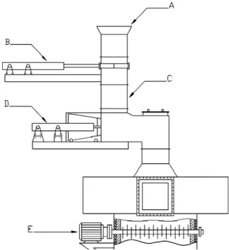
A feeding system for processing medical waste into refuse derived fuels suitable for the pyrolysis and combustion is needed before feeding medical waste into the gasifier. Two parts (primary feeder and auxiliary feeder) form the feeding system, in which med-ical wastes are mixed, grinded, compacted and preheated.Fig. 1 gives the details of the feeding system.Fig. 2gives the major fur-nace components. The primary feeder consists of a charge hopper (A inFig. 1), an access slide board (B inFig. 1), a vertical bin (C in Fig. 1) and a reciprocating propeller (D inFig. 1). Medical waste is automatically batch-fed into the gasifier (D inFig. 2). The sec-ondary feeder (E inFig. 1, E inFig. 2) is mounted in the center of the vertical gasifier. It includes two layers of shredder employing waste compacting and tumbling principles. Each layer of shredder is made up of the four pointed steel screws in line. With the rotation movement of the screws, medical wastes are mixed, shredded and continuously transported down until they impinge into the pyroly-sis and partial combustion zone at the bottom of the gasifier. Drying process is a key factor for detailed effect of the thermal disposal
Fig. 1. Schematic diagram of the feeding system. (A) Charge hopper, (B) access slide
Fig. 2. Schematic diagram of the incinerator. (A) Waste inlet, (B) screws, (C) flue gas
outlet, (D) gasifier chamber, (E) secondary feeder, (F) secondary air injector, (G) exit of gasifier, (H) secondary combustion chamber, (I) rotary grate, (J) “U” shape channel, (L) ash outlet, (M) primary air inlet.
facility as medical waste may have maximum moisture content of 50%. This process is guaranteed by the secondary feeder installed inside the gasifier. The medical waste bed can be formed on the screws and exposed to the radiation and hot gas from the under-neath. The temperature of this zone is kept at 300–400◦C to fulfill the drying process.
A vertical cylinder type reactor operating below atmospheric pressure is used as a gasifier. Its height is 6 m with an inner diame-ter of 1.2 m. The chamber’s wall is made of refractory concrete and
radiation bricks for stable heat radiation flux during incineration. Medical wastes, pyrolysates and bottom ashes slowly tumble with the rotation of the grate (I inFig. 2) mounted at the bottom of the gasifier. The combustion rate is controlled by the quantity of the primary air supplied from the underneath. A partial combustion of medical waste takes place at substoichiometric condition generat-ing a burned-out ash in the bottom zone of the chamber. The tem-perature in the bottom zone of the gasifier is kept at 800–900◦C in order to ensure the bottom ash remains as solid and does not melt. Hot gas from the gasifier is fed to the SCC (H inFig. 2) mixing with the secondary air for final combustion. The SCC has a distinct cylinder configuration, we call it “coaxial” structure, as it surrounds the gasifier with the same vertical axis. No pipeline is needed for connection with the gasifier in this case. Considerable advantage of this design is small heat losses, which has been proven in other thermal treatment process[19]. A well-known engineering design, “U”-shaped combustion channels (J inFig. 2), is employed in the SCC to increase gas turbulence and residence time in the high tempera-ture region[20]. Auxiliary fuel is supplied only when the incinerator is start, shut down and the temperature of the SCC is lower than 900◦C.
Flue gas cleaning is performed by a bag filter and a two-stage wet scrubber, in line with a quenching tower for restraining organ-ics (mainly PCDD/Fs) conversion. Glass fiber (0.3m pore size) is used as the filter material of the baghouse. Activated carbon (150 g/h) is injected in the gas stream before the fabric filter to remove heavy metals. The incineration facility is integrated with a wastewater treatment system for all the liquid effluents and scrub-ber blowdowns, and with a stabilization/solidification unit for the inertisation of fly ash and sludge residues with a cement-based mixture. Pollution control pathways are presented in detail inFig. 3.
2.3. Experimental
A 2-month period for demonstration of suitability of the MWI was allowed before giving final permission for operation. Sampling and analyzing procedures were performed by the National Environ-mental Protection Institute.
Shielded Type K thermocouples were placed at the middle of the gasifier and the bottom of the SCC. Particle concentration measur-ing was performed by the reflected infrared method and conducted with the incineration plant’s own automatic, continuous analyzing system. The gas concentrations of CO2, CO, O2, NOX, SO2in the inlet of the stack were also measured continuously by the incineration plant’s own monitoring system (FTIR-MGS300 JCT, Austria). The data of those measured air pollutants were automatically calculated and recorded in mg/m3for 11% volume of O
2. The concentration range for CO, SOXwas 0–300 mg/m3, NOXwas 0–400 mg/m3. Its accuracy and relative standard deviation were 3% and 0.5%. Several verification tests of the online monitoring system were carried out before our experiment to avoid measurement errors.
To measure other emission pollutants, an isokinetic probe was inserted to the centre of the stack. Gas sampling was performed by the filter-cooler method and conducted with an automatic, contin-uous adjusting sampling pump.
After cooling and particulate matter collection, the sampling gas passed through an aqueous solution of sodium hydroxide for HCl and HF. The analyses were conducted by colorimetry using mer-curic thiocyanate and ion selective electrode methods, respectively. It was impossible to perform pollutants measurement accurately in a unique experiment. Therefore, a series of five experiments was performed in order to reduce the experimental error. The concen-trations of emissions were determined on average value of each sample.
Metal concentrations in the gas and ash, either in particulate matter or in the gas phase, were estimated according to standard procedures. An aqueous acidic solution of hydrogen peroxide was used to absorb metals. The recovered samples were digested in 10 ml of (1:4) HCl and 4 ml of (1:1) nitric acid (HNO3) followed by heating at 85◦C for 30 min. Digested samples were filtered by filter paper and made up to 100 ml volume[21]. The metal concen-trations were determined with the help of emission spectrometer ICP-AES (Thermo Jarrell Ash). The detection limit of Cd, Cr, Cu, and Zn was 0.001 mg/l, Hg was 0.0001 mg/l, As was 0.0002 mg/l, Ni was 0.005 mg/l, Pb was 0.003 mg/l.
The PCDD/Fs sampling, cleanup, quantification and analysis were conducted in accordance with the Chinese standard [22]. Sample was quantified by HRGC/HRMS, using a HP 6890 plus gas chromatograph coupled to a mass spectrometer (Micromass AutoSpec Ultina) operating in EI mode at 35 eV and with a resolution greater than 10,000. The recovery rates of the stan-dards after extraction and cleanup procedures were between 65% and 80%. The quality control measurement was described previously[23].
All pollutant concentrations were converted to dry standard conditions (273 K and 101.3 kPa) referred to 11% O2in flue gas. The calculations were based on the measuring of flue gas flow rates and respective pollutant concentrations.
3. Results and discussion
3.1. Operational results
The running conditions of the novel MWI are summarized in Table 2. Medical waste has heterogeneous characteristic and this heterogeneity can be observed in the MWI runs.Table 2shows an important gap between settings and actual temperature in some cases, which indicates a unstable pyrolysis and incineration process. The temperature in the gasifier was set at 700◦C, while the maxi-mum temperature in the gasifier was 913◦C. As the decomposition of the organic matter is normally total at these high temperatures, it is considered that this anomaly could be due to: (a) the fluctuation of components in medical waste especially moisture content which
Table 2
Running characteristics of the novel MWI.
Content Parametera
Feeding rate (kg/h) 420 Temperature in the gasifier (◦C) 653–932
Temperature in the SCC (◦C) 867–1176 Consumption
Starting fuel Anthracite and gasoline Auxiliary fuelb(kg) 0
Water (m3/h) 0.25
Electric power (kw/h) 7.5
aOperation parameters may vary 20% due to waste heterogeneity and
composi-tion variance.
bSupplementary fuel is only used at startup process.
may lead to different delayed time of raw waste ignition, and (b) the excessive air ratio present in the gasifier which may lead to exces-sive burning of the pyrolysate. Similar phenomenon was observed in the SCC. The settings and actual minimum temperatures were 1000◦C and 860◦C, respectively. Because (a) the excessive com-bustion in the gasifier makes the lack of fuel and decline in heat release in the SCC. And (b) the secondary air absorbing excess heat in the SCC makes temperature further departure from the settings. Generally, auxiliary fuel is needed incessantly in the conven-tional two-staged MWI[2]in order to keep the temperature at the guideline limits. However, in our study, the integrative MWI reduces the heat losses effectively. Heat loss in the duct is elimi-nated as there is no duct between the gasifier and the SCC. More heat is directly carried to the SCC by the combustible gas. The coax-ial combustion chamber enhances the heat transfer between the gasifier and the SCC due to the integrative design. The heat emitted from the combustion of combustible can keep the high tempera-ture in the SCC without addition of the auxiliary fuel. Despite of waste heat value fluctuations, the temperature of the SCC has been kept higher than 850◦C which is the limit set by Chinese EPA. Large quantity of auxiliary fuel combustion is also one of the significant reasons for emission pollutants especially for MWI without APCD [11,24]. In this incinerator, supplementary fuel is only needed at start up or when the temperature of the SCC is lower than the limit (900◦C). Therefore, it is possible to conclude the amount of pollu-tants emitted to the atmosphere is only responsible by the amount of incinerated medical wastes.
3.2. Traditional air pollutants
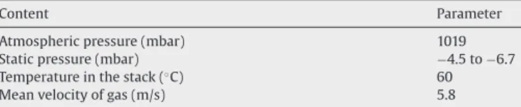
Table 3gives the features of the sampling port in the inlet of the stack.Fig. 4(a–d) shows the concentrations of PM, SO2, CO and NOX about 2 h in the inlet of stack. The fluctuated curves can be observed for all the runs due to heterogeneity and volatile components in medical waste. In this period of time, the amount of emission CO is in a range of 8–74 mg/m3with an average of 29 mg/m3. The con-centration of NOXis in a range of 58–93 mg/m3 with an average of 65 mg/m3. The SO
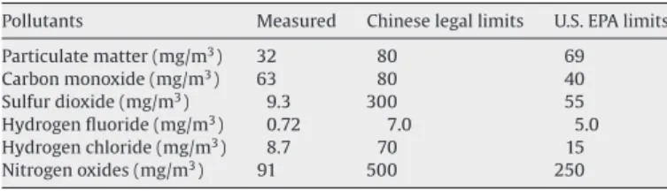
2concentration in the flue gas is in a range of 0–9.3 mg/m3.Table 4shows the measuring results of HF and HCl. The maximum air pollutant levels in the inlet of the stack are sum-marized inTable 5. Chinese and U.S. EPA limits for each component are listed in theTable 5. As shown in the Table, the measured
pollu-Table 3
Flue gas features in sampling port.
Content Parameter
Atmospheric pressure (mbar) 1019
Static pressure (mbar) −4.5 to −6.7
Temperature in the stack (◦C) 60
Fig. 4. (a) Concentration of CO vs time (11% vol. of O2), (b) concentration of SO2vs time (11% vol. of O2), (c) concentration of PM vs time (11% vol. of O2), (d) concentration of
NOXvs time (11% vol. of O2).
Table 4
Concentrations of hydrogen chloride and hydrogen fluoride.
No. Sampling time Hydrogen chloride (mg/m3) Hydrogen fluoride (mg/m3)
Measureda Measureda 1 12:00–12:20 6.2 0.34 2 12:30–12:50 8.7 0.72 3 13:00–13:20 4.1 0.51 4 13:30–14:00 7.2 0.47 5 14:00–14:20 3.0 0.33 Chinese EPA limit 70 7 U.S. EPA limit 15 5
aThe measured concentrations were recalculated at the standard percentage
oxy-gen concentration, 11%.
tants belong generally to the concentration range set by China and U.S. EPA.
Table 5shows PM level is at least a factor 2.5 below the Chinese guideline. Low PM emission is one of the major advantages for the
Table 5
Summary of maximum emission pollutants and limits.
Pollutants Measured Chinese legal limits U.S. EPA limits Particulate matter (mg/m3) 32 80 69 Carbon monoxide (mg/m3) 63 80 40 Sulfur dioxide (mg/m3) 9.3 300 55 Hydrogen fluoride (mg/m3) 0.72 7.0 5.0 Hydrogen chloride (mg/m3) 8.7 70 15 Nitrogen oxides (mg/m3) 91 500 250
pyrolysis-gasifying incineration process. The primary air supply is only 50% of the stoichiometric requirement for complete combus-tion in the gasifier, so the gas turbulence could not carry over a large amount of PM. The excess air ratio is only 20%, which is far below the excess air ration for a rotary kiln system (50–100%). The low excess air ratio reduces average flue as velocities that, in turn, reduces par-ticle entrainment in the flue gas stream. Effective removal of fine particles is obtained in the bag filter. Subsequently, toxic metals and organic compounds adsorbed onto the PM are well controlled.
Low NOXconcentration is another advantage for this integrative
MWI. As well known, this pollutant is formed during combus-tion by the oxidacombus-tion of nitrogen in the waste and the fixacombus-tion of atmospheric nitrogen. Conversion of nitrogen in the waste usually occurs at relatively low temperatures (<1000◦C), whereas fixa-tion of atmospheric nitrogen occurs at higher temperatures[20]. 70–80% of the NOXis associated with nitrogen in the waste since the gasifier operates at relatively low temperatures[25]. Low O2 levels have an inhibitive effect on the NOXformation. Liu and Ma
[9]studied NOXformation on a two-stage hospital incinerators. The air-starved process gradually became similar with the conventional mass burning process when the air supply increased in the pri-mary chamber. The NOXconcentration in the flue gas increased from 63 mg/m3to 193.2 mg/m3.
The low CO level is attributed to high combustion temperature (over 850◦C). Because the combustible gas from the gasifier is incin-erated completely with the secondary air containing rich oxygen. Good combustion practice (maximization of in-furnace destruction of trace organics) is accomplished by optimizing waste feeding
pro-Table 6
Concentration of heavy metal in flue gas and ash.
No. Pollutants Measured value Chinese EPA limits (mg/m3)
U.S. EPA limits (mg/m3) Flue gas (mg/m3) Ash (mg/kg) 1 Hg 0.012 80 0.2 2 Cd N.A. 100 0.1 1–2 total 0.012 180 0.2 3 As 0.018 200 1.0 4 Ni 0.005 140 3–4 total 0.023 340 0.1 5 Pb 0.046 540 1.6 6 Cr 0.011 210 7 Cu 0.021 310 5–7 total 0.078 1060 4.0a 5.0b
aFor the total emissions of Cr + Sn + Sb + Cu + Mn. bFor the total emission of Pb + Cr + Cu + Mn.
cedures, achieving adequate combustion temperatures, providing the proper amount and distribution of the combustion air, and opti-mizing the mixing process. A failure in any one of these components will be accompanied by increases in flue gas CO concentrations[20]. Therefore, CO levels represent the best available estimate of envi-ronmentally satisfactory operation for the incineration process. The conventional two-stage incineration system[2]is intermittently operated in a batch way so that the pyrolysis is not conducted in a stable and optimum way. Jangsawang et al.[24]reported that the batch size had a significant impact on the CO emission. Larger batch size needed more heat delivered to the raw waste and take more time to reach the preheating temperature. When the waste was heated to the volatilization temperature, the high rate of generated gas encountered the “bottleneck effect” due to the fixed SCC vol-ume, and the conversion of the CO to CO2was constrained, giving rise to high CO concentration at the SCC exit. The same result was found in Antal Halasz’s study[26]. The regulative CO peak was found in the monitoring results after medical waste was batched into the chamber. In our study, no obvious CO peak is observed inFig. 4(a). Fluctuation in the curve is due to the heterogeneous nature of med-ical wastes. Therefore, it can be concluded that the novel feeding system alleviate the adverse effects of a batch way.
3.3. Heavy metal in flue gas and ash
The concentrations of heavy metals in flue gas and ash are given inTable 6. The major metals identified in the produced ash
are Sn, Ni, Cu, Ba and B. The measured metals in flue gas are all well below the EPA emission limits. But the concentrations of heavy metals in the fly ash obviously exceed the limit values in the toxicity characteristic test. Chinese legislation law[7] pro-hibited the landfilling of the waste that exceeded the maximum values allowed for total concentrations of heavy metals. The fly ash needs a careful detoxification before their final disposal by landfilling. Mixing ash with cement followed by hardening of the resulting mixture is an attractive option to prevent future pollu-tion in case of stabilizapollu-tion of heavy metals. Mechanism of the processes occurring on immobilization, as well as the assessment of the effectiveness of solidification has been widely studied and discussed in many reports[27,28]. Sakai et al.[27]observed that under solidification with cement, hydration reaction produced a stable crystalline phases such as tobermorite and jennite, and the formation of these phases was responsible for creating filamen-tous structures that coated and held the heavy metal particles together. It reduced the rate at which the contaminants could be transported to the environment and made the toxic waste meet the requirement for long-term storage on land. Therefore, it is used for immobilization of heavy metals in ashes in this plant. The strength of hardened cement as well as heavy metal concentrations in leachate will be tested in the future experi-ments.
3.4. PCDD/Fs in stack emission
The concentrations of PCDD/Fs in stack emission are shown in Table 7. The total PCDD/Fs concentration of this MWI is 3.587 ng/m3, showing a larger magnitude than that of municipal solid waste [29]. The reason for larger PCDD/Fs concentrations in the MWI probably could be complex behavior in the ther-mal disposal process (pyrolysis, gasification and incineration), which may cause de novo formation of PCCD/Fs. Unstable combus-tion causes more products of incomplete combuscombus-tion that might be the precursors of PCDD/Fs formation. More polyvinyl chlo-ride (PVC) products may exist in medical wastes and therefore may also serve as PCDD/Fs precursors. Furthermore, it has been reported that higher concentrations of copper, iron and other metals, which are considered as the PCDD/Fs formation catalysts, could increase PCDD/Fs formation [29]. However, the value of total PCDD/Fs concentrations is within the low range for medi-cal waste incineration reported by others[11,18,30]. The different technology seems to produce a remarkable effect on the PCDD/Fs. The running results imply that this configuration makes the high temperature combustion occur easily in the SCC. This can be illustrated by the energy balance of the SCC using the following terminologies:
Table 7
Concentration of PCDDs and PCDFs in the sample.
Isomers PCDDs (ng/m3) PCDFs (ng/m3)
Mass I-TEF I-TEQ Mass I-TEF I-TEQ
2,3,7,8 T4CDD 0.003 1 0.003 T4CDF 0.04 0.1 0.004 1,2,3,7,8 P5CDD 0.007 0.5 0.0035 P5CDF 0.077 0.05 0.00385 2,3,4,7,8 P5CDF 0.015 0.5 0.0075 1,2,3,4,7,8 H6CDD 0.096 0.1 0.0096 H6CDF 0.080 0.1 0.008 1,2,3,6,7,8 H6CDD 0.076 0.1 0.0076 H6CDF 0.061 0.1 0.0061 1,2,3,7,8,9 H6CDD 0.085 0.1 0.0085 H6CDF 0.033 0.1 0.0033 2,3,4,6,7,8 H6CDF 0.048 0.1 0.0048 1,2,3,4,6,7,8 H7CDD 0.670 0.01 0.0067 H7CDF 0.774 0.01 0.00774 1,2,3,4,7,8,9 H7CDF 0.167 0.01 0.00167 O8CDD 0.712 0.001 0.000712 O8CDF 0.643 0.001 0.00643 Total PCDDs 1.649 0.039612 PCDFs 1.938 0.05339 PCDDs + PCDFs 3.587 0.093002 PCDDs/PCDFs 0.851
total heat energy entering the SCC = qT heat energy translated to the PCC = q1
heat energy consumed in heating air entering the SCC = q2 heat energy lost in the outer jacket of the SCC = q3 heat lost during SCC combustion qL= q1+ q2+ q3 net heat energy change q = qT− qL
High temperature in the SCC is maintained by (a) reducing heat loss q3in such a way that the coaxial design decreases 40% contact area of the SCC’s outer jacket with the environment, and (b) recovery heat from q1 by the pyrolysis gas flow directly carrying heat to the SCC. Apart from the temperature’s impact on PCDD/Fs emissions, resident time is another important parameter in the decomposition of PCDD/Fs in the combustion process. This parameter is ensured by the design of “U”-shape combustion channel in the SCC. Shrilli underlined that temperature, together with residence time and turbulence, was the “3T” important factor for decomposition of PCDD/Fs in the combustion process[31]. The concentrations of homologues found in sample are presented in Table 7. Highly chlorinated homologues are dominant for PCDDs and the tendency is same for PCDFs. Meanwhile, the sample con-tains a large portion of higher chlorinated OXCDD/F and HXCDD/F congeners which account for 37–53% of the total PCDD/Fs produc-tion. Therefore, the emission of PCDD/Fs from this novel plant can be contributor of the higher chlorinated congeners of PCDD/F. The I-TEQ values of 2,3,7,8-substituted PCDD/Fs are listed inTable 7. The total toxicity equivalent concentration is 0.093 ng/m3 I-TEQ. This value is below the upper limit concentration for land application according to GB18598-2001 in which the maximum PCDD/F level is 0.1 ng/m3I-TEQ.
4. Conclusions
The study deals with the detailed investigation about the emis-sions of a novel MWI. Preheating and shredding medical waste in the middle of the gasifier at 300◦C by the waste feeder were the initial steps before incineration which resulted in the stable com-bustion process. The incinerator was performed under starved air burning condition, in which the temperature of the gasifier and the SCC was around 700◦C and 1050◦C, respectively. Occurrence of the high temperature combustion in the SCC without adding auxiliary fuel indicated that the novel MWI effectively reduced the heat losses. During the experiment, it was found that the maxi-mum measured level of PM in the inlet of the stack was 32 mg/m3; CO was 63 mg/m3; SO
2 was 9.3 mg/m3; NOXwas 91 mg/m3; HCl was 8.7 mg/m3; and HF was 0.72 mg/m3. All of these pollutant lev-els belonged to the acceptable ranges set by Chinese and U.S. EPA, which confirmed that the novel installation effectively treated med-ical waste and produced stabilized product. The heavy metal in fly ash such as Cd and As still exceeded the limits at the stable run-ning condition, implying that fly ash needed detoxification for its long term storage on land. The evaluation of the heavy metals in flue gas and ash furnished an early approach to the assessment of their environmental impact. The total toxicity equivalent concen-tration (TEQ) value of PCDD/Fs in stack was 0.093 ng/m3, which was below the criteria. The TEQ tests also showed the emission of PCDD/Fs from this novel plant could be contributor of the higher chlorinated congeners of PCDD/Fs.
Acknowledgements
The authors would like to express their appreciation for the support of State Key Laboratory of Coal Combustion, Huazhong Uni-versity of Science and Technology. All engineers and technical staff at the Xiangfan ZhongYou Environmental Protection Corporation are deeply acknowledged for providing information and experi-ments together with the full analysis of combustion gases. Mr. Ho
Simon Wang, at Academic Writing Center, HUST has provided tuto-rial help to improve the manuscript.
References
[1] M.C.M. Alvim-Ferra, S.A.V. Afonso, Incineration of different types of medical wastes: emission factors for gaseous emissions, Atmospheric Environment 37 (2003) 5415–5422.
[2] C.C. Lee, G.L. Huffman, Medical waste management incineration, Journal of Hazardous Materials 48 (1996) 1–30.
[3] R.R.A.M. Mato, G.R. Kassenga, A study on problems of management of med-ical solid wastes in Dar es Salaam and their remedial measures, Resources, Conservation and Recycling 21 (1997) 1–16.
[4] M. Miyazaki, H. Une, Infectious waste management in Japan: a revised regula-tion and a management process in medical instituregula-tions, Waste Management 25 (2005) 616–621.
[5] Y.C. Jang, C. Lee, O.S. Yoon, H. Kim, Medical waste management in Korea, Journal of Environmental Management 80 (2006) 107–115.
[6] J.I. Blenkharn, Medical wastes management in the south of Brazil, Waste Man-agement 26 (2006) 315–317.
[7] State Environmental Protection Administration of China, Standard for Pollu-tion Control on the Security Landfill for Hazardous Wastes, NaPollu-tional Technical Standard of China (GB 18598-2001).
[8] State Council of China, Decree of the Medical Waste Management, Chinese Environmental Science Press, Beijing, 2003.
[9] Y.S. Liu, L.L. Ma, Investigation of novel incineration technology for hospital waste, Environment Science and Technology 40 (2006) 6411–6417.
[10] B.K. Lee, M.J. Ellenbecker, M.E. Rafael, Alternatives for the treatment and dis-posal of healthcare wastes in developing countries, Waste Management 24 (2004) 143–151.
[11] A.F. Shaaban, Process engineering design of pathological waste incinerator with an integrated combustion gases treatment unit, Journal of Hazardous Materials 145 (2007) 195–202.
[12] M.C.M. Alvim-Ferraz, S.A.V. Afonso, Incineration of healthcare wastes: manage-ment of atmospheric emissions through waste segregation, Waste Managemanage-ment 25 (2005) 638–648.
[13] W.R. Niessen, Combustion and Incineration Processes (Third Edition, Revised and Expanded), Marcel Dekker, Inc., New York, 2002, pp. 301–308.
[14] European Commission, Dioxin Emissions in the Candidate Countries: Sources, Emission Inventories, Reduction Policies and Measures, Office for Official Pub-lications of the European Communities, 2003, ISBN 92-894-6039-3. [15] D.E. Rogers, A.C. Brent, Small-scale medical waste incinerators—experiences
and trials in South Africa, Waste Management 26 (2006) 1229–1236. [16] H.M. Zhu, J.H. Yan, X.G. Jiang, Y.E. Lai, K.F. Cen, Study on pyrolysis of typical
med-ical waste materials by using TG-FTIR analysis, Journal of Hazardous Materials 153 (2008) 670–676.
[17] H. Huang, L. Tang, Treatment of organic waste using thermal plasma pyrolysis technology, Energy Conversion and Management 48 (2007) 1331–1337. [18] J. Heikkinen, H. Spliethoff, Waste mixture composition by thermogravimetric
analysis, Journal of Thermal Analysis and Calorimetry 72 (2003) 1031–1039. [19] R. Dvorak, R. Stulir, P. Cagas, Efficient fully controlled up-to-date equipment
for catalytic treatment of waste gases, Applied Thermal Engineering 27 (2007) 1150–1157.
[20] J. Marjorie, Clarke, N.Y. Bronx, Introduction to Municipal Solid Waste Incinera-tion, Air and Waste Management Association Annual Meeting Baltimore, June 2002, pp. 23–27.
[21] J. Scancar, R. Milacic, M. Strazar, O. Burica, Total metal concentrations and par-titioning of Cd, Cr, Cu, Fe, Ni and Zn in sewage sludge, Science of The Total Environment 250 (2000) 9–19.
[22] State Environmental Protection Administration of China, Determination of polychlorinated dibenzo-p-dioxins and polychlorinated dibenzo-p-furans by isotope dilution HRGC/HRMS, National Technical Standard of China: HJ/T 77-2001.
[23] Y.W. Ni, Z.P. Zhang, Q. Zhang, J.P. Chen, Y.N. Wu, X.M. Liang, Distribution patterns of PCDD/Fs in chlorinated chemicals, Chemosphere 60 (2005) 779–784. [24] W. Jangsawang, B. Fungtammasan, S. Kerdsuwan, Effects of operating
parame-ters on the combustion of medical waste in a controlled air incinerator, Energy Conversion and Management 46 (2005) 3137–3149.
[25] M. Goemans, M. Clarysse, J. Joannes, P.D. Clercq, Catalytic NOx reduction with simultaneous dioxin and furan oxidation, Chemosphere 54 (2004) 1357–1365. [26] A. Halasz, PCDD/F emission control by intermediate dust removal at medical
waste incinerators, Waste Management & Research 14 (1996) 3–14.
[27] E. Sakai, S. Miyahara, S. Ohsawa, S.H. Lee, M. Daimon, Hydration of fly ash cement, Cement and Concrete Research 35 (2005) 1135–1140.
[28] T. Mangialardi, A.E. Paolini, A. Polettini, P. Sirini, Optimization of the solidifica-tion/stabilization process of MSW fly ash in cementitious matrices, Journal of Hazardous Materials B70 (1–2) (1999) 53–70.
[29] B.L. Walker, C.D. Cooper, Air pollution emission factors for medical waste incin-erators, Journal of Air and Waste Management Association 42 (1992) 784–789. [30] T. Chen, J.H. Yan, S.Y. Lu, Characteristic of polychlorinated dibenzo-p-dioxins and dibenzofurans in fly ash from incinerators in china, Journal of Hazardous Materials 150 (2008) 510–514.
[31] A. Shrilli, G. Minnni, E. Guerriero, M. Rotatori, M.L. Molinelli, V. Lotito, PCDD/Fs emissions from hospital waste incineration, in: Proceedings of the European Combustion Meeting, 2003.