Science Arts & Métiers (SAM)
is an open access repository that collects the work of Arts et Métiers Institute of Technology researchers and makes it freely available over the web where possible.
This is an author-deposited version published in: https://sam.ensam.eu Handle ID: .http://hdl.handle.net/10985/10781
To cite this version :
Eric SEMAIL, Xavier KESTELYN, Alain BOUSCAYROL - Sensitivity of a 5-phase Brushless DC machine to the 7th harmonic of the back-electromotive force - In: Power Electronics Specialists Conference, 2004. PESC 04. 2004 IEEE 35th Annual, Allemagne, 2004-06 - PESC - 2004
Any correspondence concerning this service should be sent to the repository Administrator : archiveouverte@ensam.eu
Sensitivity of a 5-phase Brushless DC machine
to the 7
thharmonic of the back-electromotive force
E. Semail, X. Kestelyn and A. Bouscayrol
L2EP, Laboratoire d'Electrotechnique et d' Electronique de Puissance de Lille ENSAM Lille 8 bd Louis XIV F-59046 LILLE, France
e-mail: eric.semail@lille.ensam.fr http://www.univ-lille1.fr/l2ep/
Abstract—This paper presents a vector control of a
5-phase drive composed of a 5-leg Pulse Width Modulation (PWM) Voltage Source Inverter (VSI) supplying a permanent-magnet Brushless DC (BLDC) machine with trapezoidal waveform of the back-electromotive force (EMF). To achieve this control a machine Multi-converter model is used: the 5-phase machine is transformed into a set of two 2-phase fictitious machines which are each one controlled in a (d,q) frame as 3-phase machines with sine waveform back-EMF. In comparison with the 3-phase BLDC drives, the 5-phase ones present one
particularity: a high sensitivity to the 7th harmonic of
back-EMF. Experimental results show that the 7th harmonic of
back-EMF, which represents only 5% of RMS back-EMF, induces high amplitude parasitic currents (29 % percent of RMS current). The model allows to explain the origin of this sensitivity and how to modify simply the control algorithm. Experimental improvements of the drive are presented.
Index Terms—brushless, multiphase, 5-phase, drive
control.
I. INTRODUCTION
Multi-phase drive systems have several advantages over conventional 3-phase ones [1]-[2] such as higher reliability and reduction of torque ripples. Multi-phase machines have been initially supplied from Pulse Amplitude Modulation Current Stiff Inverter (PAM CSI)
[3]-[5].In this case, a machine with q 3-phase stars can
be considered as the association of q 3-phase machines mechanically coupled on the same shaft. Each 3-phase fictitious machine is associated with one of the q stars. This decomposition is possible in spite of the magnetic couplings between the stars, because of one property of the PAM CSI drive: when there is commutation of a current in a star, the currents in the other stars have constant values. The mutual inductances between stars have no impact and the stars can be then considered as magnetically independent.
With Digital Signal Processor, it is now possible to use PWM VSI in multi-phase drives [6]-[8].
If vector controls of 3-phase BLDC machines are well known [9], it is not the case for multi-phase ones, particularly if the waveform of back-EMF is trapezoidal. PWM-VSI requires a much more precise modeling than PAM CSI: it is no more obvious to decompose the multi-phase machine into a set of 3-multi-phase machines.
For six-phase induction machines, [10] has proposed a multiple reference frame analysis based on an orthogonal transformation. The natural frame (a,b,c,d,e,f) of the 6-phase machine is transformed into a set of three independent frames (o1,o2), (d,q) and (z1,z2) where
dynamic equations of the machine are totally decoupled.
When currents are sinusoidal, the planes (o1,o2) and
(z1,z2) do not participate to electromechanical conversion.
Recently, using the same transformation, [11] shows the possibility to improve torque density with the injection of a third harmonic current, harmonic which is relative to the plane (o1,o2). For 5-phase induction machines, similar
transformations have been used to achieve a DTC control [7] or to drive with only a 5-leg VSI supply two series connected motors [12]. Multi-phase BLDC machines have been less studied [13]-[15] than multi-phase induction machines. In [13], torque density has been increased with 3rd harmonic current injection in a 5-phase
synchronous reluctance motor drive.
In this paper, a 5-phase BLCD supplied by a 5-leg PWM-VSI is studied. Using a Multi-machine Multi-converter description, this drive is broken down into two fictitious machines which can be controlled independently. This
specific modeling shows that the 7th harmonic of the
EMF leads to important parasitic currents. Controls strategies are deduced from this analysis and experimental results are provided.
II. MODELING OF THE DRIVE
A. Equivalent set of two 2-phase fictitious drives
Under assumptions of no saturation and no reluctance effects, the vectorial approach developed in [16]-[19] allows to define the equivalence of a 5-phase wye-connected machine Fig. 1) to a set of two fictitious independent drives, each one being composed of one fictitious machine and one fictitious inverter.
Vb u s
ν1 i1
Fig. 1. Symbolic representation of the leg PWM-VSI and 2p pole 5-phase machine
The symmetry and the circularity of the stator inductance matrix are used to achieve the equivalence between the actual and the fictitious drives:
[ ]
⎟⎟ ⎟ ⎟ ⎟ ⎠ ⎞ ⎜⎜ ⎜ ⎜ ⎜ ⎝ ⎛ = 1 2 2 1 1 2 2 1 1 2 2 1 1 2 2 1 M M M M L M M M M L M M M M L M M M M L Ls (1)[Ls] matrix has three eigenvalues, named cyclic
inductances, whose associated eigenspaces Gg are
orthogonal each others. The dimension of an eigenspace
Gg is equal to the multiplicity of its corresponding
eigenvalue Lg. In the studied case, the multiplicity of two
of them (noted Lm and Ls) is of order two.
The orthogonality of the three eigenspaces Gm, Gg and G0
implies that three independent flux of energy can be found. To prove this assertion, an euclidian space with the usual canonic dot product is associated with the 5-phase machine. This space is provided with an orthonormal base
{
x1,x2,x3,x4,x5}
. In this natural base, voltage and current vectors are defined:• v =v1x1+v2x2+...+v5x5 (2)
• i =i1x1+i2x2+...+i5x5 (3)
The coordinates of a vector in this base are the measurable values relative to each phase.
Using the dot product, the electric power is expressed by:
i v i v p k k k k s . 5 1 = =
∑
= = (4) Then, every vector is split into the sum of three vectors, each one belonging to an eigenspace, Gm, Gs and G0:0 s
m y y
y
y = + + (5)
As the eigenspaces are orthogonal, the electric power is also the sum of three powers, associated each one with an eigenspace: 0 0. . . .i v i v i v i v ps = = m m+ s s+ (6)
The wye-connection of the machine implies thati0=0
Continuing the same energetic approach, it is easy to express the torque of the 5-phase machine as the sum of
two torques Tm and Ts associated respectively to the
eigenspaces Gm and Gs:
s m T T
T = + (7)
Each torque Tm and Ts is expressed as the following dot
product: m srm m d i d T . θ φ = and s srs is d d T . θ φ = (8) with
• θ , the mechanical angular position;
• φ , the flux vector whose coordinate φsr srk is the flux
through the phase k exclusively produced by the permanent magnets.
Moreover, as the control of the 5-leg VSI is achieved with a 2-level PWM, only average values of voltages are assumed to be imposed by the VSI. Using the same transformation as with the machine, the VSI is decomposed into two fictitious VSI. To get a characterization of each fictitious VSI it is sufficient to project the 25 characteristic vectors of the 5-leg VSI onto
the two eigenspaces Gm and Gs. Two polyhedrons are
obtained (Fig. 2 and Fig. 3).
Consequently there are two 2-phase machines represented in Fig. 4 by MM, the Main Machine and by SM, the Secondary Machine. The MM (resp. SM) is
characterized by its back-EMF em (resp. es ), its
cyclic inductance Lm (resp. Ls) and its torque Tm (resp.
Ts). These two drives are mechanically coupled: they
have the same mechanical angular velocity Ω. They are
supplied each one by a VSI, these two VSI being electrically coupled by a mathematical transformation.
-300 -150 0 150 300 -300 -150 0 15O 300 A 01 02 03 04 05 06 07 08 09 10 11 12 13 14 15 16 17 18 19 20 21 22 23 24 25 26 27 28 29 30 Set A={0,31}
Fig. 2 Space Vector Representation of to the VSI which supplies MM
A 01 02 03 04 05 06 07 08 09 10 11 12 13 14 15 16 17 18 19 20 21 22 23 24 25 26 27 28 29 30 -300 -150 0 150 300 -300 -150 0 15O 300
Fig. 3: Space Vector Representation of to the VSI which supplies SM
B. Harmonic analysis of fictitious drives
It is now interesting to characterize these fictitious machines to be able to control and supply them correctly. The expression (8) shows that the torque Tm and Ts are
the dot product of the vectorial projections of two vectors. The first one is only depending on the design of the machine, the second one is imposed by the power supply.
As dφ dsr/ θ is a 2π/p periodic function, it can be
expanded into a Fourier series and consequently expressed as a sum of vectors associated with space harmonic order number k. Properties of symmetry, due to the regular manufacturing assumption, involve, as usual, the cancellation of cosine terms and of even sine terms.
Moreover, when a vector linked to a the space harmonic number k is projected onto an eigenspace the result depends on k. According to the considered eigenspace associated with the fictitious studied machine, the null terms of the Fourier series are not the same. There is a distribution of the different space harmonics between the eigenspaces.
This particularity is verified for every vector which has the same mathematical properties as dφ dsr/ θ. Thus, it is possible to associate to each fictitious machine a characteristic family of time or space harmonics:
• the Main Machine (MM) is associated with odd harmonics of 5h±1 order: 1, 9, 11, 19,…
• the Secondary Machine (SM) is associated with odd harmonics of 5h±2 order: 3, 7, 13, 17,…
• the G0 eigenspace is associated with odd harmonics
of h5 .
In TABLE I is given harmonic decomposition of
experimental back EMF Fig. 5).
TABLE I
HARMONIC DECOMPOSITION OF BACK-ELECTROMOTIVE OF ONE PHASE
Order of harmonic 1 3 5 7 9 Relative RMS amplitude E1=100% E3=29% E5=12,4% E7=5,1% E9=1,7% 0 0.005 0.01 0.015 0.02 0.025 0.03 0.035 0.04 -50 -40 -30 -20 -10 0 10 20 30 40 50
Fig. 5. Back-EMF of the machine
One can remark that the MM is almost a machine with a
sinusoidal back-EMF since the 9threpresents only 1,7%
of the first harmonic. For the SM the 7th harmonic of
back-EMF, which is only 5,1% of the fundamental,
represents 18% of the 3rd harmonic. Consequently, the
back-EMF of SM can not be considered sinusoidal because it is composed of 3rd and 7th harmonics.
III. DEDUCED CONTROL OF EXPERIMENTAL SET UP
Using causal EMR formalism (see Appendix on EMR formalism) , the control structure is easily deduced by systematic inversion (Fig. 7). Thanks to this structure it appears clearly that a choice must be done to define the two references Tm-ref and Ts-ref from a torque reference
Tem-ref. This is due to the mechanical coupling expressed
by equation (7). This kind of choice is common in Multi-Machine Multi-Converter systems and has been formalized in [20].
The control laws are then easy to implement because algorithms, already developed for 3-phase drives, can be directly used for each fictitious machine. Nevertheless, both fictitious machines have not the same reference frame. The first space harmonic of MM is the fundamental and implies that the angular velocity of the
frame is pΩ. The first harmonic of SM is the 3rd space
harmonic and implies that the angular velocity of the
frame is 3pΩ. A more usual synopsis of the control is
presented in Fig. 8.
Fig. 6. experimental bench
T
em=T
m+T
sΩ
M M
SM
T
mT
sΩ
Fictitious machines Fictitious VSIv
busi
bus DC bus Electricalcoupling M echanical coupling
v
esi
emv
emi
esv
sv
mi
mi
se
mi
mi
se
sTwo fictitious drives
Load s s s s dt v e i d L = − i .s es =Ts Ω
To exhibit easily at first the sensitivity of the 7th space
harmonic of back-EMF, the adopted strategy consists in using only the MM: Tm-ref = Tem-ref ; Ts-ref = 0. As the most
important harmonics in the SM are the 3rd and 7th ones,
the choice of Ts-ref = 0 induces that the 3rd time harmonic
current must be equal to zero. Then the 7th time harmonic
is almost the only one in the SM as it appears in (Fig. 12, Fig. 14).
A. Analysis of 7th harmonic back-EMF effect
The 7th harmonic of back-EMF induces currents in the
SM.
i1-7, the RMS magnitude of these currents, is estimated by
the following formula:
(
7 L)
1A R E i 2 s 2 s 7 7 1 = + = − Ω . Asthe inductance Ls of the SM is much more smaller than
v
m_refT
em refT
em=T
m+T
sΩ
MM
SM
T
mT
sΩ
Fictitious machines
Fictitious VSI
v
busi
busDC bus
Electrical
coupling
Mechanical
coupling
v
esi
emv
emi
esv
sv
mi
mi
se
mi
mi
se
sLoad
T
s refT
m refi
s_refi
m_refv
s_ref?
Fig. 7: Control structure of the 5-phase BLCD deduced from EMR
imq-ref + -P I m imd-ref + -+ -P I s + -P I s Trans forma tion
PWM
VSI
i
1, i
2, i
3, i
4 isq-ref i sd-ref R(θ) R(3θ) R -1(θ) R-1 (3θ) θ θ vpα-ref vpβ-ref vsβ-ref vsα-ref +-Ω
réf IP Repartition of reference torquesθ
Ω
Tem-ref v1ref v2ref v3ref v4ref v5ref P I m 0 0 Trans forma tionmachine
Resolver C ⎥ ⎥ ⎥ ⎥ ⎥ ⎥ ⎥ ⎥ ⎥ ⎥ ⎥ ⎥ ⎦ ⎤ ⎢ ⎢ ⎢ ⎢ ⎢ ⎢ ⎢ ⎢ ⎢ ⎢ ⎢ ⎢ ⎣ ⎡ = 5 16 sin 5 16 cos 5 8 sin 5 8 cos 2 1 5 12 sin 5 12 cos 5 6 sin 5 6 cos 2 1 5 6 sin 5 6 cos 5 4 sin 5 4 cos 2 1 5 4 sin 5 4 cos 5 2 sin 5 2 cos 2 1 0 1 0 1 2 1 5 2 π π π π π π π π π π π π π π π π C ⎥ ⎦ ⎤ ⎢ ⎣ ⎡ − = θ θ θ θ θ pp pp R cos sin sin cos ) ( C-1the inductance Lm of the MM, this explains that even if E7
is equal to 5,1% of E1 then i1-7 represents 29 % of i1-1
(Fig. 12).
B. Compensation of 7th harmonic back-EMF effect
A compensation of this back-EMF in the SM has been implemented: Fig. 11, Fig. 13 and Fig. 15 show improvements of the control. Fig. 9 gives more global results of the control.
C. Increasing torque using both fictitious machines
As the back-EMF of SM is not equal to zero, it is possible to increase the torque with a same modulus of
i . Considering that Tem is the dot product of
θ φ d
d sr/ by i , the instantaneous value of Tem is
maximum if dφ dsr/ θ and i are collinear vectors.
Taking into account only the 1st and the 3rd harmonics,
the repartition between Tm-ref and Ts-ref is then 29% (the
same repartition as between E1 and E3,TABLE I).
IV. CONCLUSION
An original modeling of a 5-phase machine allows to exhibit particularity of this kind of machine compared with 3-phase one. The sensitivity of the 5-phase drive to the 7th space harmonic is easily explained. Moreover, the
EMR modeling allows to find how to compensate the
high magnitude parasitic currents induced by the 7th
harmonic of back-EMF. Experimental results show then improvements. Finally, a control where the two fictitious drives are simultaneously supplied is presented. The algorithms are the same as those already used in 3-phase machines. 0 0.005 0.01 0.015 0.02 0.025 0.03 0.035 0.04 0.045 0.05 -8 -6 -4 -2 0 2 4 6 8 A s i1
Fig. 10: Experimental i1 current in phase n°1 at 1000 rpm without
compensation of 7th harmonic of back-EMF
0.005 0.01 0.015 0.02 0.025 0.03 0.035 0.04 0.045 -8 -6 -4 -2 2 4 6 i1 s 0 0.05 0 8 A
Fig. 11: Experimental i1 current in phase n°1 at 1000 rpm with
compensation of 7th harmonic of back-EMF
0 5 0 1 0 0 1 5 0 2 0 0 2 5 0 3 0 0 3 5 0 4 0 0 4 5 0 5 0 0 0 0 . 5 1 1 . 5 2 2 . 5 3 3 . 5 4 4 . 5 5 F u n d a m e n t a l o f i1: i1 - 1 7t h h a r m o n ic o f i 1 : i1 - 7 1 0 0 % 2 9 % S M M M H z
Fig. 12: Spectrum of experimental current i1 at 1000 rpm without
compensation of 7th harmonic of EMF
0 5 0 1 0 0 1 5 0 2 0 0 2 5 0 3 0 0 3 5 0 4 0 0 4 5 0 5 0 0 0 0 . 5 1 1 . 5 2 2 . 5 3 3 . 5 4 4 . 5 5 F u n d a m e n ta l o f i1: i1 -1 7 th h a r m o n ic o f i 1 : i1 -7 M M S M H z
Fig. 13: Spectrum of experimental current i1 at 1000 rpm with
compensation of 7th harmonic of EMF
0 0.005 0.01 0.015 0.02 0.025 0.03 0.035 0.04 0.045 -8 -7 -6 -5 -4 -3 -2 -1 0 1 0 0.005 0.01 0.015 0.02 0.025 0.03 0.035 0.04 0.045 -3 -2 -1 0 1 2 3
i
mq-regi
mq-refi
md-regi
md-refi
sq-ref=i
sd-refi
sq-regi
sd-regSM
MM
0.05 0.05Fig. 14: Currents in the two fictitious 2-phase machines ‘MM’ and ‘SM’ withoutcompensation of 7th harmonic of back-EMF
0 0.005 0.01 0.015 0.02 0.025 0.03 0.035 0.04 0.045 -3 -2 -1 0 1 2 3 0 0.005 0.01 0.015 0.02 0.025 0.03 0.035 0.04 0.045 0.05 -8 -7 -6 -5 -4 -3 -2 -1 0 1
i
mq-refi
mqi
mdi
md-refi
sq-ref=i
sd-refi
sqi
sdSM
MM
0.05Fig. 15: Currents in the two fictitious 2-phase machines ‘MM’ and ‘SM’ with compensation of 7th harmonic of back-EMF
0 0 . 5 1 1 . 5 2 2 . 5 3 3 . 5 4 4 . 5 - 1 5 - 1 0 - 5 0 5 1 0 1 5 2 0 im q is q Ω r e f Ω m e s
Fig. 9. Experimental active currents in MM and SM with compensation of 7th harmonic of back-EMF and T
0 0 . 0 0 5 0 . 0 1 0 . 0 1 5 0 . 0 2 0 . 0 2 5 0 . 0 3 0 . 0 3 5 0 . 0 4 0 . 0 4 5 0 . 0 5 - 6 - 4 - 2 0 2 4 6 i1
Fig. 16: Experimental i1 current in phase n°1 at 1000 rpm with compensation of 7th harmonic of
back-EMF and the repartition between MM and SM isq-ref = (29%) imq-ref.
0 1 2 3 4 5 6 7 8 9 10 -25 -20 -15 -10 -5 0 5 10 15 20 25 imq isq Ωref Ωmes
Fig. 17: Experimental active currents in MM and SM with compensation of 7th harmonic of
back-EMF and Tes-ref = (29 %) Tms-ref
0 0.005 0.01 0.015 0.02 0.025 0.03 0.035 0.04 0.045 0.05 -2 -1 0 1 2 3 4 isq isd SM isq-ref isd-ref 0 0.005 0.01 0.015 0.02 0.025 0.03 0.035 0.04 0.045 0.05 -8 -7 -6 -5 -4 -3 -2 -1 0 1 imd imd-ref imq-ref imq MM
Fig. 18: Currents in the two fictitious 2-phase machines ‘MM’ and ‘SM’ withcompensation of 7th harmonic of back-EMF 0 50 100 150 200 250 300 350 400 450 500 0 0.5 1 1.5 2 2.5 3 3.5 4 4.5 5 7th harmonic Fundamental of i1: i1-1 3rd harmonic of i 1: i1-3 100% 29% SM MM
Fig. 19: Spectrum of Fig. 16 experimental current i1
APPENDIX ON EMR FORMALISM
The Energetic Macroscopic Representation (EMR) [22] is a synthetic graphical tool based on the principle of action and reaction between elements [21]. It leads to a synthetic description of an overall conversion system between two sources (oval green pictogram). It uses elements which accumulate energy (rectangular orange pictogram with an oblique bar) and elements which convert energy without energy or storage (orange square for electrical conversion, circle for electromagnetic conversion and triangle for mechanical conversion). From the EMR of an electromechanical conversion, one can deduce a control structure, which is composed of the maximum of control operations and measurements [22]. This modeling has successfully been applied to electric vehicles, high-speed railway traction systems, wind energy conversion systems, ship propulsion with double-star induction machines.
EMR of an energy conversion — An energy conversion
between two sources S1 and S2 is represented by an
association of power components (Fig. 20): a conversion element and two accumulation elements. All of them are connected by exchange vectors.
A source element produces a state variable (output). The source is either a generator or receptor. It is disturbed by the reaction of the connected element (input), for example, the absorbed current for a voltage grid.
A conversion element yields an energy conversion without energy loss nor storage. Its tuning is ensured by an input vector ectun which consumes less power than the
transferred one. In some case, there is no tuning input and the conversion transfer is realized with a fixed rate. An accumulation element connects an energy source to a conversion element, thanks to an energy storage, which induces at least one state variable. Such element has no tuning input.
The exchange vectors yield the energy to be transferred between the connected components according to the principle of action and reaction. On Fig. 20, the source S1
is chosen arbitrarily as the upstream source. It produces an action which is transmitted then to the downstream source S2 which answers by a reaction. So, one defines a
chain of action variables (ai) and a chain of reaction
variables (ri). These variables can be scalar or vector. The
two connected components are dual each other: if the action is potential, the reaction is kinetic.
Extension to Multi-machine Multi-converter Systems (MMS) — A MMS is composed of several
mono-machine mono-converter systems, which share one or
S1 ae1 CE ae2 cetun S2 a1 a2 a3 a4 r1 r2 r3 r4
more power devices. Thus, it yields energy distribution between electric and mechanical sources through coupled conversion chains, which can yield interactions (disturbances) between power structures. The MMS have to enable best power repartition with lower cost equipment.
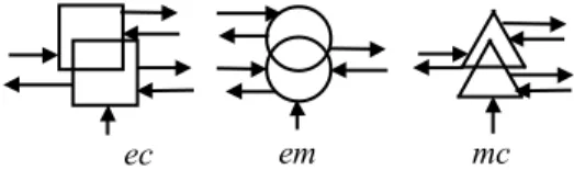
The energy distribution is obtained by specific conversion structures [19]. These power components are common to several conversion chains. They are called coupling structures. A coupling conversion structure links an upstream device with many downstream one's, or vice versa. Such structures are drawn by forms with intersections (Fig. 21).
The electric coupling is associated with electric converters. It corresponds to a common electric device of several converters (power switch, capacitor...). It leads to a common electric variable (voltage, current...).
The magnetic coupling is associated with electric machines.
The mechanical coupling is associated with mechanical converters.
ACKNOWLEDGMENT
This work is part of the project ’Futurelec2’ within the ’Centre National de Recherche Technologique (CNRT) of Lille’. The support of the CNRT is kindly acknowledged.
REFERENCES
[1] T.M. Jahns “ Improved reliability in solid state ac drives by means of multiple independent phase-drive units”, IEEE Transactions on Industry Applications, vol. IA-16, May-June 1980, pp. 321-331.
[2] H.A. Toliyat, ”Analysis and Simulation of Five-Phase Variable-Speed Induction Motor Drives Under Asymmetrical Connections”, IEEE Transactions on Power Electronics, vol. 13 no 4, July 1998, pp. 748-756.
[3] R. Bhatia, H. Krattiger, A. Bonanini, D. Schafer, J.T. Inge, G.H. Sydnor, “ Adjustable Speed Drive With A Single 100-MW Synchronous Motor”, ABB Review, Issue no 6, 1998, pp.14-20. [4] H. Godfroi, P. Bosc , “ Large variable speed drives using
synchronous motors and frequency converters”, Alstom Review, no 6, 1986.
[5] S.D. Sudhoff, “Analysis and average-value modelling of dual line-commutated converter 6-phase synchronous machine systems”, IEEE Transactions on Energy Conversion, vol. 8, no. 3, September 1993, pp. 411-417
[6] S. Siala S., E. Guette, J. L. Pouliquen, “ Multi-inverter PWM control: a new generation drives for cruise ship electric propulsion”, European Power Electronics Conference (EPE’2003) , September 1993, Toulouse (France), CD-ROM. [7] H. Xu, H. A. Toliyat, L. J. Petersen, “Five-Phase Induction Motor
Drives With DSP-Based Control System”, IEEE Transactions on Power Electronics, vol. 17 no 4, July 2002, pp. 524-533. [8] J. Cros, C. Paynot, J. Figueroa, P. Viarouge, “Multi-Star PM
brushless DC motor for traction applications”, European Power Electronics Conference (EPE’2003), Toulouse (France), September 2003, CD-ROM.
[9] D.W. Novotny, T.A. Lipo, Vector Control and dynamics of AC drives, New York, Oxford University Press Inc, 2000.
[10] Y. Zhao, T. A. Lipo, “ Space Vector PWM Control of Dual Three-Phase Induction Machine Using Space Vector Decomposition ”, IEEE Transactions on Industry Applications, vol. 31 no.5, September/October 1995, pp. 1100-1109.
[11] R. O. C. Lyra, T.A. Lipo, “ Torque Density Improvement in a Six-Phase Induction Motor With Third Harmonic Current Injection”, IEEE-IAS annual meeting 2001, September/October 2001, Chicago (USA), CD-ROM.
[12] E. Levi, M. Jones, S.N. Vukosavic, H.A. Toliyat, “A Five-Phase Two-Machine Vector Controlled Induction Motor Drive Supplied from a Single Inverter”, European Power Electronics Conference (EPE2003), Toulouse (France), September 2003, CD-ROM. [13] R. Shi R., H. A. Toliyat, A. El-Antably, “Field Oriented Control
of Five-phase Synchronous Reluctance Motor Drive with Flexible 3rd Harmonic Current Injection for High Specific Torque “, IEEE-IAS annual meeting 2001, September/October 2001, Chicago (USA), CD-ROM.
[14] J. Figueroa, J. Cros, P. Viarouge, “Current Control Strategies for Seven Phase Brushless DC Motors”, International Congress on Electrical Machines (ICEM’02), August 2002, Brugges (Belgium), CD-ROM.
[15] G. Simões, P. Vieira, “A High-Torque Low-Speed Multiphase Brushless Machine—A Perspective Application”, IEEE Transactions on Industrial Electronics, vol. 49, no. 5, October 2002, pp. 1154-1164.
[16] E. Semail, A. Bouscayrol, J.P. Hautier, “Vectorial formalism for analysis and design of polyphase synchronous machines”, EPJ AP (European Physical Journal-Applied Physics), vol. 22 no 3, June 2003, pp. 207-220.
[17] E. Semail, "Tools and studying method of polyphase electrical systems. Generalization of the space vector theory", Ph.D. thesis, University of Sciences and Technologies of Lille, June 2000 (text in French).
[18] X. Kestelyn, "Vectorial Multi-machine Modeling for the control of Multi-phase drives ", Ph.D. thesis, University of Sciences and Technologies of Lille, December 2003 (text in French).
[19] X. Kestelyn, E. Semail, JP. Hautier, “Vectorial Multi-machine modeling for a five-phase machine”, International Congress on Electrical Machines (ICEM’02), August 2002, Brugges (Belgium), CD-ROM.
[20] A. Bouscayrol, B. Davat, B. de Fornel, B. François, J. P. Hautier, F. Meibody-Tabar, E. Monmasson, M. Pietrzak-David, H. Razik, E. Semail, M. F. Benkhoris, "Control Structures for Multi-machine Multi-converter Systems with upstream coupling", Mathematics and Computers in Simulation, vol. 63, no3-5, November 2003, pp. 261-270 (common paper of GE44, GREEN, L2EP, LEEI and SATIE according to the MMS project of GDR-ME2MS).
[21] A. Bouscayrol , B. Davat, B. De Fornel, B.François, J. P. Hautier, F. Meibody-Tabar, M. Pietrzak-David, "Multi-machine multi-converter systems: applications to electromechanical drives", EPJ Applied Physics, Vol. 10, no. 2, May 2000, pp131-147 (common paper of GREEN, L2EP and LEEI, according to the MMS project of GDR-SDSE).
[22] A. Bouscayrol, X. Guillaud, J. P. Hautier, Ph. Delarue, “Macro-modeling of electromechanical conversion; application to the electrical machine control”, (text in French), RIGE, Vol. 3, no.2, June 2000, pp 257-282.
ec em mc