Université de Montréal
Manganese, Copper and Zinc catalysts in rac-lactide polymerization
par Pargol Daneshmandkashani
Département de Chimie Faculté des Arts et des Sciences
Thèse présentée
en vue de l’obtention du grade de
Philosophiæ Doctor (Ph.D)
en chimie
Juillet 2018
Abstract
Diiminopyrrolide ligands bearing two chiral N-methylbenzyl substituents were prepared by a condensation reaction of the 1H-pyrrole-2,5-dicarbaldehyde and S-methylbenzylamine. Reaction of the ligand with Cu(OMe)2 in the presence of 2 equiv
of pyridylmethanol or dimethylaminoethanol yielded the dimeric Cu(II) catalysts L2Cu2(µ-OR)2. Application of these complexes in rac-lactide polymerization gave
isotactic (Pm = 0.73) and atactic (Pm = 0.50) PLA, respectively. Kinetic studies
conducted on these two complexes indicated the presence of two different active species. GPC results obtained for the copper catalyst containing two pyridylmethoxide bridges indicate the growth of only one chain per dimer (thus one alkoxide remains as a spectator ligand), while in the complex bearing two dimethylaminoethoxides both alkoxides inserted lactide. A ligand mediated chain-end control mechanism, which is accomplished by the epimerization of the catalytic site based on the chirality of the last inserted unit, is proposed. The presence of a coordinated and an uncoordinated imine “arms” facilitates epimerization since it requires only dissociation/re-coordination. The effects of the ligand framework (steric bulk) on activity and stereocontrol of the catalyst were investigated by variation of the imine substituents to benzyl, bromobenzyl, xylyl, diphenylmethyl and cyclohexyl. Benzyl, bromobenzyl and cyclohexyl were the only imine substituents providing the desired dimeric copper catalyst with pyridylmethoxide. Benzyl and cyclohexyl substituted complexes produced isotactic PLA. Substituent chirality was thus not required for stereocontrol. The bromobenzyl-substituted complex was the only one providing an atactic catalytic site with both imines coordinated and produced atactic PLA.
Monoiminopyrrolide copper(II) complexes with pyridylmethoxide ligands were prepared with naphtyl, diphenylmethyl, xylyl and 2,6-diisopropylphenyl N-substituents. They showed reduced stereocontrol which is assumed to be due to slower epimerization (rotation around the Cu-pyrrole bond is now required). All complexes provided isotactic PLA, but the stereocontrol did not surpass that of the
diiminopyrrolide complexes. Substitution of the 5-position of the pyrrole by chloride led to loss of activity while a methyl substituent provided atactic PLA.
Phenoxy-imine ligands were prepared by a condensation reaction of the salicylaldehyde derivative and the desired amine (benzyl, cyclohexyl, xylyl and diphenylmethyl). Their complexes bearing either dimethylaminoethoxide or pyridylmethoxide ligands were structurally similar to the iminopyrrolide complexes. All complexes were active in rac-lactide polymerization, but although GPC results indicated the growth of only one chain per dimer for the pyridylmethoxide complexes and thus indicated a similar active species, only atactic PLA was produced.
A zinc analog of the isotactic copper complex with the N,N’-bis(methylbenzyldiiminopyrrolide ligand was prepared and structurally characterized, but produced heterotactic PLA (Pr = 0.75). Zinc complexes with
2,4-di-tert-butyl-6-aminomethyl-phenol ligands with amino = N,N,N’,N’-tetramethyldiethylenetriamine or di-(2-picolyl)amine substituents were prepared and structurally characterized. They showed a chiral tetrahedral zinc center with one coordinated and one uncoordinated for the ethylenediamine substituents and a five-coordinated zinc center with both amino groups coordinated for picolylamine. NMR investigations indicated fast epimerization of the metal center on the NMR time scale. Both zinc complexes are highly active in lactide polymerization and reach full conversion in only a few minutes, placing them among the most active zinc catalysts known. Slightly isotactic PLA (Pm up to 0.6) was obtained for both complexes, showing in proof-of-principle
the advantage of introducing catalytic site epimerization. The picolylamine-substituted complex showed a suppression of stereocontrol at high catalyst concentrations, which is not fully understood.
Bulk polymerization of lactide was conducted with manganese diamino-diphenolate complexes following a coordination-insertion mechanism. Their activity was low and only heterotactic PLA was obtained. Tri/tetradentate phenoxy-imine copper complexes were likewise used in bulk polymerization, following an activated monomer mechanism with benzyl alcohol as co-initiator. Polymerizations were stable in air and in the presence of water or acetic acid, but polymer molecular weight
control was low with evidence for facile intramolecular transesterification reactions. Surprisingly high heterotacticities were obtained in molten monomer (Pr up to 0.85),
but there was no evidence that the additional basic site on the ligand participates in stereocontrol.
Keywords: Catalysis, Copper complexes, Manganese complexes, polylactic acid,
Résumé
Des ligands diiminopyrrolides portant deux substituants N-méthylbenzyle chiraux ont été préparés par condensation du 1H-pyrrole-2,5-dicarbaldéhyde et de la S-méthylbenzylamine. La réaction de ce ligand avec du Cu(OMe)2 en présence de 2
équivalents de pyridylméthanol ou de diméthylaminoéthanol a donné les catalyseurs dimèriques de Cu(II) L2Cu2(µ-OR)2. L'application de ces complexes dans la
polymérisation du rac-lactide a permis d’obtenir respectivement des PLA isotactiques (Pm = 0,73) et atactiques (Pm = 0,50). Les études cinétiques menées sur ces deux
complexes ont indiqué la présence de deux espèces actives différentes. Les résultats de GPC obtenus pour le catalyseur cuivrique contenant deux pyridylméthoxyde pontant indiquent la croissance d'une seule chaîne par dimère (un des alcoolates reste en tant que ligand spectateur), alors que dans le cas du complexe portant deux diméthylaminoéthoxydes, les deux alcoolate attaquent le lactide. Un mécanisme de "ligand mediated chain-end control", se faisant par l'épimérisation du site catalytique par rapport à la chiralité de la dernière molecule de lactide insérée, est proposé. La présence d'un "bras" iminé coordonné et non coordonné facilite l'épimérisation car celle-ci ne nécessite qu'une dissociation / ré-coordination. Les effets du ligand (encombrement stérique) sur l'activité et le stéréocontrôle du catalyseur ont été étudiés par utilisations de divers substituants sur l’imine : benzyle, bromobenzyle, xylyle, diphénylméthyle et cyclohexyle. Les subtituants iminobenzyle, -bromobenzyle et -cyclohexyle one été les seuls fournissant les catalyseurs de cuivre dimèrique désiré avec le pyridylméthoxyde. Les complexes portant les groupes benzyle et cyclohexyle ont produit du PLA isotactique. La chiralité portée par le liguand n'était donc pas requise pour le stéréocontrôle. Le complexe bromobenzyl-substitué a été le seul à fournir un site catalytique achirale avec les deux imines coordinées et produit un PLA atactique.
Des complexes monoiminopyrrolidiques de cuivre(II) avec des ligands pyridylméthoxydes ont été préparés avec des substituants imino Nnaphtyle, -diphénylméthyle, -xylyle et -2,6-diisopropylphényle. Ils ont démontré un stéréocontrôle réduit, qui est présument due à une épimérisation plus lente (une
ont fourni des PLA isotactiques, mais le stéréocontrôle obtenu n'a pas dépassé celui des complexes diiminopyrrolidiques. La substitution de la position 5 du pyrrole par un Chlore conduit à une perte d'activité tandis qu'un substituant méthyle fournit un PLA atactique.
Les ligands phénoxy-imine ont été préparés par condensation de dérivée de salicylaldéhydes et d’une amine (benzyle, cyclohexyle, xylyle et diphénylméthyle). Leurs complexes de Cuivre(II) portant soit un ligand diméthylaminoéthoxyde ou pyridylméthoxyde étaient structurellement similaires aux complexes iminopyrrolidiques. Tous les complexes étaient actifs dans la polymérisation du rac-lactide, mais bien que les résultats GPC indiquaient la croissance d'une seule chaîne par dimère pour les complexes de pyridylméthoxyde et ainsi une espèce active similaire, seul du PLA atactique était produit.
Un analogue de zinc du complexe de cuivre isotactique avec le ligand N,N'-bis (méthylbenzyl-diiminopyrrolide) a été préparé et structurellement caractérisé, mais a produit du PLA hétérotactique (Pr = 0,75). Les complexes de zinc de
2,4-di-tert-butyl-6-aminométhylphénol, où les substituants amino sont le N,N,N',N'-tétraméthyldiéthylènetriamine ou le di-(2-picolyl)amine ont été préparés et structurellement caractérisés. Ils ont montré un centre zincique tétrahédrique chiral avec un "bras" coordiné et un non coordinné pour l'éthylènediamine et un centre zincique pentacoordiné avec les deux groupes picolylamine. Les analyses par RMN ont indiqué une épimérisation rapide du centre métallique, sur l'échelle de temps de la RMN.
Les deux complexes de zinc sont hautement actifs dans la polymérisation du lactide et atteignent une conversion complète en seulement quelques minutes, les plaçant parmi les catalyseurs de zinc les plus actifs connus à ce jour. Un PLA légèrement isotactique (Pm jusqu'à 0,6) a été obtenu pour les deux complexes, démontrant en
principe l'avantage de l'introduction d'un site catalytique capable de s’épimériser. Le complexe substitué par le ligand picolylaminique présentait une suppression du stéréocontrôle à des concentrations élevées de catalyseur, qui n'est pas entièrement compris.
La polymérisation en masse du lactide a été réalisée avec des complexes de manganèse diamino-diphénolate suivant un mécanisme de coordination-insertion. Leur activité était faible et seul un PLA hétérotactique a été obtenu. Des complexes tri / tétradentate de phénoxy-imine-cuivrique ont également été utilisés dans la polymérisation en masse, en suivant un mécanisme de monomère activé et utilisant de l'alcool benzylique en tant que co-initiateur. Les polymérisations étaient stables dans l'air et en présence d'eau ou d'acide acétique, mais le contrôle du poids moléculaire du polymère était faible du à des réactions de transestérification intramoléculaire aisées. Des PLA hétérotactiques étonnamment élevées ont été obtenues dans le monomère fondu (Pr jusqu'à 0,85), mais il n'y avait aucune preuve
que le site basique additionnel des ligands participe au stéréocontrôle.
Mots clés : Catalyse, complexes de cuivre, complexes de manganèse, acide
Table of Content
Abstract ... v
Résumé ... ix
Table of Content ... xiii
Table list ... xix
Figure list ... xxi
Scheme list ... xxix
Abreviation list ... xxxi
Acknowledgment ... xxxvii
Chapter 1 . Introduction ... 1
1. History of polymers ... 3
2. Different types of polymers ... 4
2.1. Natural and semi-synthetic polymers ... 5
2.2. Synthetic polymers ... 6
3. Biodegradation ... 8
4. Bioplastics ... 9
4.1. Polyhydroxybutyrate (PHB) ... 10
4.2. Polycaprolactone (PCL) ... 10
4.3. Polylactic acid (PLA) ... 10
4.3.1. Production of lactic acid ... 13
4.3.2. Production of PLA ... 14
4.3.3. Lactide ... 17
7. Stereocontrol ... 21
7.1. Stereocontrol mechanisms ... 24
7.1.1. Catalytic-site mediated chain-end control mechanism ... 25
8. Catalysts used in the ROP of lactide ... 27
8.1. Most popular catalysts for the production of PLA ... 27
8.1.1. Aluminum ... 27
8.1.2. Tin ... 28
8.1.3. Zinc ... 29
8.2. Catalysts applied to the ROP of lactide based on their ligand frame ... 30
8.2.1. Salen and Salan ligands ... 30
8.2.2. Tetradentate and tridentate Schiff-base ligands ... 33
8.2.3. β-Diketiminato ligands ... 37
8.2.4. Amino(bisphenolato) and amino(trisphenolato) ligands ... 39
8.3. Copper catalysts used in lactide polymerisation ... 41
9. Aim of this work ... 47
References Chapter 1 ... 49
Chapter 2 . Exploring the Reactivity of Manganese(III) Complexes with Diphenolate-diamino Ligands in rac-Lactide Polymerization ... 57
Abstract ... 59
Introduction ... 60
Results and Discussion ... 61
Synthesis. ... 61
UV/vis-spectra. ... 63
Magnetic moments. ... 64
Lactide polymerization. ... 67
Experimental section ... 73
References Chapter 2 ... 79
Chapter 3 . Mechanism and Stereocontrol in Isotactic rac-Lactide Polymerization with Copper(II) complexes ... 85
Abstract ... 87
Introduction ... 88
Results and Discussion ... 90
Schlenk equilibria. ... 90
Polymerization kinetics. ... 90
Nuclearity of the active species in 3.1. ... 93
EPR measurements. ... 100
Influence of the bridging ligand on stereocontrol. ... 104
Solvent dependence of stereocontrol. ... 109
Origin of stereocontrol. ... 110
Influence of the pending imine. ... 112
Conclusions ... 115
Experimental Section ... 116
References Chapter 3 ... 126
Chapter 4 . Diiminopyrrolide Copper Complexes: Synthesis, Structures and rac-Lactide-Polymerization Activity. ... 131
Abstract ... 133
Ligand synthesis. ... 136
Attempted synthesis of copper alkoxide complexes. ... 137
Reactions with chelating alcohols. ... 142
rac-Lactide polymerization – activity. ... 153
Polymer molecular weight control. ... 157
Stereocontrol. ... 161
Mechanism of stereocontrol. ... 164
Conclusions ... 165
Experimental section ... 166
References Chapter 4 ... 184
Chapter 5 . Catalytic-site-mediated chain-end control in the polymerization of rac-lactide with copper iminopyrrolide complexes ... 191
Abstract ... 193
Introduction ... 193
Results and discussion ... 197
Impact of sterically bulky ligands on stereocontrol. ... 197
Lactide polymerization. ... 200
Impact of site-epimerization on stereocontrol. ... 203
Impact of catalytic-site symmetry on stereocontrol. ... 204
Conclusion ... 206
Experimental section ... 207
Chapter 6 . Dinuclear iminophenoxide copper complexes in rac-Lactide polymerisation 227
Abstract ... 229
Introduction ... 229
Results and discussion ... 232
Iminophenols - ligand and general complex synthesis. ... 237
Salicylaldehyde-based ligands. ... 239 4,6-di(tert-butyl)salicylaldehyde-based ligands. ... 244 1,3-dichlorosalicylaldehyde-based ligands. ... 247 Conclusion ... 248 Experimental ... 248 References Chapter 6 ... 261
Chapter 7 . Configurationally Flexible Zinc Complexes as Catalysts for rac-Lactide Polymerisation ... 271
Abstract ... 273
Introduction ... 274
Results and discussion ... 276
Diiminopyrrolide complexes ... 276
Synthesis and structure. ... 276
rac-Lactide polymerisation. ... 278
Triaminophenolate complexes ... 279
Syntheses and structures. ... 281
rac-Lactide polymerisation. ... 285
References Chapter 7 ... 301
Chapter 8 . Tetradentate aminophenolate copper complexes in rac-lactide polymerization ... 309
Abstract ... 311
Introduction ... 311
Results and discussions ... 314
Conclusions ... 327
Experimental section ... 327
References Chapter 8 ... 335
Chapter 9 . Conclusions ... 341
Annexes ... 349
Supporting information Chapter 2... xxxix Supporting information Chapter 3... xlv Supporting information Chapter 4... lxv Supporting information Chapter 5... lxxxv Supporting information Chapter 6... xcv Supporting information Chapter 7... cv Supporting information Chapter 8... cxiii
Table list
Table 2.I. Selected bond distances [Å] and bond angles [°] from X-ray diffraction
studies ... 66
Table 2.II. rac-lactide polymerization with 2.3a, 2.3b and 2.5a·MeOH a ... 68
Table 2.III. Rac-lactide polymerization with 2.5a·MeOH in the presence of protic impurities a ... 70
Table 2.IV. Effect of additional alcohol on rac-lactide conversion at different reaction times a ... 72
Table 2.V. Details of X-ray diffraction studies ... 77
Table 3.I. rac-Lactide polymerization catalyzed by 3.1 – 3.11 ... 92
Table 3.II. Selected bond distances (Å) and bond angles (°) for 3.5, 3.6 and 3.8 – 3.11. ... 98
Table 3.III. Stereocontrol (Pm) in polymerizations with benzyl alcohol as chain-transfer reagent. ... 112
Table 3.IV. Experimental and simulated distributions of stereoerror tetrads. ... 113
Table 3.V. Details of X-ray Diffraction Studies ... 123
Table 4.I. Selected bond lengths (Å) and angles (°) of 4.1c and 4.4c. ... 140
Table 4.II. Selected geometric data for pyridylmethoxide complexes 4.1, 4.5, and 4.7-4.11 a ... 146
Table 4.III. Selected geometric data for dimethylaminoethoxide complexes 4.3b and 4.5b-4.11b a ... 152
Table 4.IV. Apparent first-order rate constants for rac-lactide polymerization with complexes 4.1-4.11 and 4.1b-4.11b. ... 156
Table 4.V. Selected results for rac-lactide polymerization with 4.5-4.11 and 4.3b-4.11b a ... 160
Table 4.VI. Stereocontrol by in-situ formation of pyridylmethoxide species. ... 163
Table 4.VII. Details of X-ray Diffraction Studies ... 178
Table 5.I. Bond distances [Å] and bond angles [deg] in iminopyrrolide copper complexes. ... 199
Table 5.III. rac-Lactide polymerization with 5.4 at different lactide concentrations. a
... 204
Table 5.IV. Details of X-ray diffraction experiments. ... 212
Table 6.I. Bond distances [Å] in crystal structures of 6.2a, 6.3b and 6.4a ... 234
Table 6.II. rac-lactide polymerizations a ... 235
Table 6.III. Selected geometric data for heteroleptic copper complexes ... 242
Table 6.IV. Details of X-ray Diffraction Studies ... 259
Table 7.I. Selected geometric data for pyridylmethoxide complexes 7.1 and 7.2 a . 278 Table 7.II. Geometrical details for the X-ray structures of 7.8-7.10. ... 283
Table 7.III. rac-Lactide polymerisation with 7.7 and 7.10. ... 287
Table 7.IV. Experimental details of X-ray diffraction studies ... 300
Table 8.I. Bond lengths in the X-ray structures of 8.1-8.6 ... 316
Table 8.II. Summary of rac-lactide polymerizations with 8.1-8.6/1 equiv benzyl alcohol a ... 318
Figure list
Figure 1.1. Jӧns Jakob Berzelius (left) and Hermann Staudinger (right) (taken from
an open access source).7 ... 3
Figure 1.2. Different types of polymer sources and their examples.9 ... 4
Figure 1.3 Cellulose (top) and starch (bottom). ... 6
Figure 1.4. Wallace Carothers (taken from an open access source).7 ... 7
Figure 1.5. Poly(ethylene terephthalate). ... 7
Figure 1.6. Polyhydroxybutyrate (PHB). ... 10
Figure 1.7. Polycaprolactone (PCL). ... 10
Figure 1.8. Different applications of PLA (taken from an open access source).7 ... 11
Figure 1.9. Pollution caused by plastics (taken from an open access source).7 ... 12
Figure 1.10. Edmonton composting facility (taken from an open access source).7 ... 12
Figure 1.11. The two configurations of lactic acid. ... 14
Figure 1.12. Coordination-insertion ROP mechanism. ... 16
Figure 1.13. Different stereoisomers of lactide. ... 17
Figure 1.14. The effect of the kpropagation/kinitiation ratio on the molecular weight of the obtained polymer chains. ... 19
Figure 1.15. Intramolecular and intermolecular transesterification. ... 19
Figure 1.16. Living and immortal polymerization. ... 21
Figure 1.17. meso and racemic diads. ... 22
Figure 1.18. Isotactic, syndiotactic and heterotactic diads. ... 23
Figure 1.19. Different stereoselectivities of produced PLA chains. ... 24
Figure 1.20. Catalytic-site control and chain-end control mechanism. ... 25
Figure 1.21. Okuda Scandium complex. ... 25
Figure 1.22. Tin(II) bis(2-ethylhexanoate). ... 28
Figure 1.23. The structure of catalysts 1 and 2. ... 30
Figure 1.24. The structure of catalyst 3. ... 31
Figure 1.25. The structure of catalysts 4 and 5. ... 31
Figure 1.26. The structure of catalysts 6 and 7. ... 32
Figure 1.29. The structure of catalysts 13 and 14. ... 33 Figure 1.30. The structures of catalysts 15, 16 and 17. ... 34 Figure 1.31. The structure of catalyst 18. ... 34
Figure 1.32. The structures of catalysts 19 and 20. ... 35
Figure 1.33. The structure of catalyst 21. ... 35
Figure 1.34. The structure of catalyst 22. ... 36
Figure 1.35. The structure of catalyst 23. ... 36
Figure 1.36. The structure of catalyst 24. ... 37
Figure 1.37. The structure of catalyst 25. ... 37
Figure 1.38. The structures of catalysts 26 and 27. ... 38
Figure 1.39. The structure of catalyst 28. ... 39
Figure 1.40. The structure of catalysts 29, 30, 31 and 32. ... 39
Figure 1.41. The structure of catalyst 33. ... 40
Figure 1.42. The structure of catalysts 34, 35 and 36. ... 40
Figure 1.43. The structure of catalyst 37. ... 41 Figure 1.44. The structure of catalyst 38. ... 42
Figure 1.45. The structure of catalysts 39, 40 and 41. ... 42 Figure 1.46. The structure of catalysts 42, 43, 44 and 45. ... 43 Figure 1.47. The structure of catalyst 46. ... 43 Figure 1.48. The structure of catalyst 47. ... 44 Figure 1.49. The structure of catalyst 48. ... 45
Figure 1.50. The structure of catalyst 49. ... 45
Figure 1.51. The structure of catalysts 50, 51 and 52. ... 46
Figure 1.52. The structure of catalysts 53, 54, 55 and 56. ... 46
Figure 1.53. The structure of catalysts 57 and 58. ... 47
Figure 2.1. UV/vis spectra in methanol of manganese complexes 2.3a (solid bold),
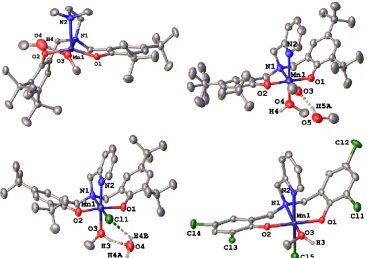
2.3b (solid thin), 2.4b·MeOH (dashed bold), 2.4b·MeOH (dashed thin) and 5a·MeOH (dotted). ... 64 Figure 2.2. X-ray structure of 2.3a (top left), 2.5a·MeOH (top right), 2.4a·MeOH
probability. Hydrogen atoms (except those on methanol or water molecules) omitted for clarity. ... 67
Figure 3.1. Polymerization kinetics of 3.1 (circles) and 3.2 (triangles). Two independent experiments (filled and hollow symbols) are shown for each catalyst.The left inset shows an enlargement of the first two hours, the right inset the linearized plot according to a pseudo-first order rate law. Conditions: [catalyst] = 2 mM, [rac-lactide] = 200 mM, C6D6, ambient temperature. ... 91 Figure 3.2. Polymer molecular weight in rac-lactide polymerizations with 3.1 in the presence of benzyl alcohol (spheres), pyridyl methanol (triangles) or trityl alcohol (diamond) and with 3.2 in the presence or absence of benzyl alcohol (squares). Polymer molecular weights were extrapolated to full conversion, i. e. Mn,corrected = Mn
/ yield. The two lines correspond to the theoretical polymer molecular weight expected if either 1 or 2 alkoxide groups per catalyst initiate polymerization. ... 94
Figure 3.3. Improved molecular weight control upon addition of trityl alcohol as a chain-transfer reagent. ... 95
Figure 3.4. Crystal structure of 3.5 (left) and 3.6 (right). Thermal ellipsoids are shown at the 50% probability level. Hydrogen atoms were omitted for clarity. Complex 3.5 cocrystallized with (3.L)Cu2(OR)2Cl (L = diiminopyrrole, Fig. 3.S7,
omitted here for clarity), which is not expected to participate in polymerization (see sup. inf.). ... 100
Figure 3.5. Experimental (bold line) and simulated (thin line) EPR-spectra of polymerization reactions with 3.1 and 3.2. ... 102
Figure 3.6. Crystal structures of 3.83.10. Thermal ellipsoids are drawn at the 50% probability level. Hydrogen atoms and the minor components of rotational disorder of the N-substituent at N3 (8) and N6 (10) were omitted for clarity. ... 108
Figure 3.7. Titration of 3.1 with pyridine. Solid lines represent experimental spectra, dotted lines are simulated spectra. Equilibrium constant K and the spectrum of the pyridine adduct were obtained by non-linear regression analysis using all spectra assuming a 1:1 equilibrium. A scale factor was added to allow for complex decomposition and refined to ±1% for 1 – 100 equiv pyridine, –3% for 200 and –6%
Figure 3.8. Pm-values determined for polymerizations with 3.1 at different
conversions. ... 111
Figure 3.9. Crystal structure of 3.11. Thermal ellipsoids are drawn at the 50% probability level. Hydrogen atoms, minor component of the disorder at N3 and the second, independent molecule of similar geometry in the unit cell were omitted for clarity. ... 114
Figure 4.1. X-ray structures of 4.1c (left) and 4.4c (right). Hydrogen atoms were omitted for clarity. Thermal ellipsoids were drawn at the 50% probability level. .... 139
Figure 4.2. X-ray structures of 4.2d and 4.3d. Thermal ellipsoids are drawn at 50% probability. Hydrogen atoms, other independent molecules (4.3d) and minor components of disordered N-substituents (4.3d) were omitted for clarity. ... 141
Figure 4.3. X-ray structures of 4.5, 4.7, and 4.9-4.11. Thermal ellipsoids are drawn at the 50% probability level. Hydrogen atoms, toluene solvent (4.11) and a second independent molecule of similar geometry (4.10 and 4.11) omitted for clarity. ... 145
Figure 4.4. Crystal structure of 4.1e, 4.4e and 4.6e. Hydrogen atoms and two of the
three independent molecules in 6e were omitted for clarity. Thermal ellipsoids were drawn at the 50% probability level. ... 148
Figure 4.5. X-ray structures of 4.3b and 4.5b – 4.11b. Thermal ellipsoids are drawn
at the 50% probability level. Hydrogen atoms and disorder of the N-substituent (4.3b,
4.8b) omitted for clarity. ... 151 Figure 4.6. Conversion/time plots for addition of several batches of monomer over several days. Black arrows indicate time of monomer addition. Top left, blue circles:
4.8, [4.8] = 1 mM in C6D6, addition of 200, 200 and 25 equiv of rac-lactide. Top
right, blue circles: 4.8, 3 mM, 300, 200, 100 equiv. Middle, red circles: 4.8b, 3 mM, 300, 200, 100 equiv. Bottom left, blue triangles: 4.9, 3 mM, 300, 100, 100, 200 equiv. Bottom right, blue triangles: 4.9b, 3 mM, 300, 100, 200 equiv. Solid lines are based on pseudo-first-order rate constants determined in the first addition. ... 154
Figure 4.7. Polymer molecular weights in rac-lactide polymerizations with 4.8 (blue circles) and 4.8b (red squares) in the presence of benzyl alcohol. Polymer molecular weights were corrected for yield (Mn,corr. = Mn / yield) to allow comparison with the
alkoxide per catalyst dimer initiating. Red dashed line: for both alkoxides initiating. Hollow circles and squares show the respective polydispersities (right axis). ... 159
Figure 4.8. Isotacticities (Pm, left axis, black circles) and polymer molecular weights
(Mn, right axis, blue squares) obtained for polymerizations of rac-lactide with 4.1b in
the presence of varying amounts of pyridylmethanol. The solid lines represent values expected if reaction of 4.1b or 4.1b* with pyridylmethanol first forms 4.1, to then initiate polymerization to form the active species 4.1*. The dashed lines show the values expected if reaction with pyridylmethanol directly forms the active species
4.1* without passing via 4.1. ... 162 Figure 5.1. Crystal structures of 5.2-5.5. Thermal ellipsoids are drawn at 50% probability (at 30% for 5.2). Hydrogen atoms, a second independent molecule (5.4) and the minor component of N-aryl disorder (5.4) omitted for clarity. ... 199
Figure 5.2. Semi-logarithmic conversion-time plot for rac-lactide polymerizations with 5.2 (circles), 5.3 (squares), 5.4 (triangles) and 5.5 (diamonds). ... 200
Figure 5.3. 13C{1H}-NMR of PLA obtained with 5.4. Left: carbonyl region, right: methine region. Tetrad assignments according to ref. 113, 114. ... 202
Figure 5.4. Crystal structure of 5.9. Hydrogen atoms and the minor part of the
disorder omitted for clarity. Thermal ellipsoids shown at the 50% probability level. ... 206
Figure 6.1. X-ray structures of 6.2a, 6.3b and 6.4a. Thermal displacements are
shown at the 50% probability level. Hydrogen atoms and the minor part of the aminoethoxide disorder in 6.4a were omitted for clarity. ... 233
Figure 6.2. Conversion-time profiles for rac-lactide polymerization with 6.4a (diamonds), 6.5a (squares, 6.6a (circles) and 6.6b (triangles). Conditions: C6D6, RT,
0.2 M lactide, 2 mM [cat.]. The inset shows the semi-logarithmic plot. Solid lines represent in both graphics theoretical conversions with the values obtained in linear regression analysis: 6.4a: kapp = 0.604(2) h–1, t0 = –4 min, 6.5a: kapp = 0. 0.80(1) h–1,
t0 = –1 min. ... 237 Figure 6.3. X-ray structures of 6.5a, 6.6a, 6.6b, and 6.16a and 6.16b. Thermal displacements are shown at the 50% probability level. Hydrogen atoms were omitted
Figure 6.4. X-ray structures of 6.8b, 6.9a, 6.10a, and 6.11b and 6.12b. Thermal
displacements are shown at the 50% probability level. Hydrogen atoms and solvent (6.8b) were omitted for clarity. Only one of two independent molecules shown for
6.8b. ... 245 Figure 6.5. Conversion-time profiles for rac-lactide polymerization with 6.8b (squares), 6.9a (circles) and, 6.11b (triangles). Conditions: C6D6, RT, 0.2 M lactide, 2
mM cat.. The inset shows the semi-logarithmic plot. Solid lines represent in both graphics theoretical conversions with the values obtained in linear regression analysis: 6.8b: kapp = 0.57(2) h–1, t0 = 102 min, 6.9a: kapp = 0. 0.78(1) h–1, t0 = –19
min, 11b: kapp = 1.1(1) h–1, t0 = 23 min. ... 246 Figure 7.1. X-ray structure of 7.2. Thermal ellipsoids are drawn at the 50% probability level. Hydrogen atoms omitted for clarity. ... 278
Figure 7.2. Conversion-time profile for rac-lactide polymerisation with 7.2. The inset shows the semi-logarithmic plot. Solid lines represent theoretical curves based on linear regression of the linear region in the semi-logarithmic plot. ... 279
Figure 7.3. X-ray structure of 7.8. Thermal ellipsoids are drawn at the 50% probability level. Hydrogen atoms and minor fractions of disorder in tert-butyl and dimethylaminoethylene substituents omitted for clarity. ... 282
Figure 7.4. X-ray structure of 7.9. Thermal ellipsoids are drawn at the 50%
probability level. Hydrogen atoms and the second, independent molecule in the asymmetric unit omitted for clarity. ... 285
Figure 7.5. Conversion-time profiles for rac-lactide polymerisation with 7.7. Conditions: C6D6, RT, 7.7:lactide = 1:100. The inset shows the semi-logarithmic plot.
Solid lines correspond to theoretical conversions based on rate constants obtained from linear regression: Black triangles: [7.7] = 2.0 mM, kobs = 4.1(1) h–1, t0 = –5 min,
final conversion after >7 h: 99%; blue diamonds: [7.7] = 0.5 mM, kobs = 0.73(1) h–1, t0
= –5 min, final conversion after >7 h: 67%. The negative axis intercept might indicate partial catalyst decomposition in the first 5 min of the reaction, inhomogeneous starting conditions or – although unlikely – experimental error. ... 286
Figure 7.6. Variation of polymer microstructure (Pm) in dependence of conversion or
time in rac-lactide polymerisations with 7.7. Black triangles: [7.7] = 2.0 mM, blue diamonds: [7.7] = 0.5 mM. With [7.7] = 0.5 mM, conversion plateaued at 67%. .... 288
Figure 7.7. X-ray structure of 7.11. Thermal ellipsoids are drawn at the 50% probability level. Hydrogen atoms, and the second, independent molecule in the asymmetric unit omitted for clarity. ... 289
Figure 8.1. X-ray structures of 8.1 (left), 8.2 (middle) and 8.3 (right). Thermal ellipsoids are drawn at 50% probability. Hydrogen atoms other than those of water, non-coordinated anions, the second independent molecule for 8.3, and the minor fraction of the disordered nitrate in 8.3 omitted for clarity. ... 315
Figure 8.2. Conversion-time plot for the polymerization of rac-lactide with
8.1/benzyl alcohol at 140 °C. lactide: 8.1:BnOH = 100:1:1. Black squares: single
experiment with aliquots taken at desired times. Reaction was exposed to air during sampling. Blue diamonds: Series of 5 independent polymerization experiments quenched after 2, 4, 7 and 24 h. Reactions were not exposed to air. The inset shows the semi-logarithmic plot. Solid lines are theoretical conversions using the apparent first-order rate constant determined from the linear region of the semi-logarithmic plot. ... 317
Figure 8.3. rac-Lactide polymerization with 8.1/BnOH with different ratios of benzyl
alcohol. Conditions: 140 °C, neat monomer, lactide: 8.1 = 100:1, BnOH: 8.1 = 1 (blue diamonds, 5 separate experiments), 1 (brown squares), 2 (black triangles), 4 (blue hollow diamonds), and 8 (red circles). The solid lines are theoretical conversions based on the pseudo-first-order rate constant determined from the linear region of the semilogarithmic plot (conversion < 70%). Left: Conversion-time plots, Upper Right: Semilogarithmic plots, Lower Right: Dependence of the observed pseudo-first-order rate constant on benzyl alcohol concentration. ... 319
Figure 8.4. Conversion-time plot for the polymerization of rac-lactide with 8.2 (blue diamonds). Data for 8.1 under identical conditions is provided for comparison (black squares). Conditions: 140 °C, lactide:[Cu]:BnOH = 100:1:1. The inset shows the semilogarithmic plot. Solid lines represent theoretical conversions based on the
pseudo-first-order rate constant determined by linear regression of the semilogarithmic plots. ... 320
Figure 8.5. Conversion-time plot for the polymerization of rac-lactide with 8.1 in the presence of ammonium salts: 1 equiv [NEt4]Cl (black triangle), 4 equiv [NEt4]Cl
(hollow triangle), 1 equiv [NEt3H][TsO] (red circle), 4 equiv [NEt3H][TsO] (hollow
circle). Conditions: 140 °C, lactide:[Cu]:BnOH = 100:1:1. The inset shows the semilogarithmic plot. Solid lines represent theoretical conversions based on the pseudo-first-order rate constant determined by linear regression of the semilogarithmic plots for t>120 min. ... 321
Figure 8.6. Conversion-time plot and the semilogarithmic plot for rac-lactide polymerizations with 8.3. Conditions: lactide:3:BnOH = 100:1:1 (blue diamonds), 100:1:4 (red circles). ... 322
Figure 8.7. X-ray structures of 8.4-8.6. Thermal ellipsoids drawn at 50% probability level. Hydrogen atoms, the second independent molecule in 5 and the anion disorder in 4 omitted for clarity. ... 324
Figure 8.8. Conversion-time plot and the semilogarithmic plot for rac-lactide polymerizations with 8.4. Conditions: lactide:4:BnOH = 100:1:1. Hollow diamonds are independent reactions quenched after 0.5, 2, 4, and 7 h without exposing the reaction to air. In the remaining four experiments samples were taken in the desired intervals, exposing the reaction to air. Two reactions were conducted with twice (diamonds) or half (triangles) the total amount of reactants to verify the influence of external impurities. ... 325
Figure 8.9. Conversion-time plot and the semilogarithmic plot for rac-lactide polymerizations with 8.6. Conditions: lactide:6:BnOH = 100:1:1 (squares, triangles), 100:1:4 (circles). Lines represent theoretical conversions calculated from the pseudo-first-order rate constants obtained from the linear regions of the semilogarithmic plot. ... 326
Scheme list
Scheme 1.1. Anionic ROP mechanism. ... 15 Scheme 1.2. Activated monomer ROP mechanism. ... 16 Scheme 1.3. Two-step reaction for the synthesis of lactide. ... 18 Scheme 1.4. The synthesis of the Scandium complex with the bulkiest substituents. 26 Scheme 1.5. The proposed stereocontrol mechanism. ... 27 Scheme 1.6. Coordination-insertion mechanism for the Al(Oi-Pr)3-catalyzed ROP of
lactide. ... 28
Scheme 2.1. ... 61 Scheme 2.2. ... 62 Scheme 2.3. ... 63 Scheme 2.4. ... 71 Scheme 3.1. Dependence of stereocontrol on the initiating group in polymerizations
with 3.1 and 3.2. ... 89
Scheme 3.2. Potential Schlenk-equilibrium for 3.1 ... 90 Scheme 3.3. Attempted preparation of 3.4 ... 96 Scheme 3.4. Preparation of 3.5 and 3.6 ... 100 Scheme 3.5. Proposed mechanism for lactide polymerization with 3.1 and 3.2. The
structures proposed for 3.1b/3.2b are representative examples of a possible structure. ... 105
Scheme 3.6. Preparation of 3.7a and 3.8. ... 107 Scheme 3.7. Preparation of 3.9 – 3.11 ... 111 Scheme 3.8. Interplay of catalytic-site inversion and stereoerror insertion. The C, C, R/A, A, S – configuration was arbitrarily chosen as a stereomatch between catalytic
site and chain end. ... 114
Scheme 4.1. ... 134 Scheme 4.2. ... 136 Scheme 4.3. ... 137 Scheme 4.4. ... 138 Scheme 4.5. ... 142
Scheme 4.7. ... 149 Scheme 4.8. ... 162 Scheme 4.9. ... 166 Scheme 5.1. ... 195 Scheme 5.2. ... 195 Scheme 5.3. Catalyst systems showing catalytic-site mediated chain-end control. RR
and SS denote R,R- and S,S-lactide ... 196
Scheme 5.4. ... 198 Scheme 5.5. ... 205 Scheme 6.1. ... 230 Scheme 6.2. ... 232 Scheme 6.3. ... 233 Scheme 6.4. ... 239 Scheme 6.5. ... 241 Scheme 6.6. ... 247 Scheme 7.1. ... 274 Scheme 7.2. ... 275 Scheme 7.3. ... 277 Scheme 7.4. ... 281 Scheme 7.5. ... 282 Scheme 7.6. ... 284 Scheme 7.7. ... 289 Scheme 7.8. ... 290 Scheme 8.1. ... 313 Scheme 8.2. ... 314 Scheme 8.3. ... 315 Scheme 8.4. ... 323
Abreviation list Ac acetyl Ar aryl Bn benzyl br broad tert-Bu tert-butyl
CCVC Centre en Chimie Verte et Catalyse CIF crystallographic information file chemical shift (in ppm)
d doublet
DCM dichloromethane diip 2,6-diisopropylphenyl
eq. equivalent
Et ethyl
EPR electron paramagnetic resonance GPC gel permeation chromatography
HMBC heteronuclear multiple bond correlation HMDS bis(trimethylsilyl)amide
HRMS high resolution mass spectrometry HSQC heteronuclear single quantum coherence J coupling constant (in NMR)
m multiplet
m meso
MALDI matrix-assisted laser desorption ionization
Me methyl
MLCT metal-ligand charger transfer
Mn number-average molar mass
MS mass spectrometry
Mw weight-average molar mass
nacnac diketiminato
NMR nuclear magnetic resonance
NSERC National Science and Engineering Research Council PDI polydispersity index
Ph phenyl
PLA polylactic acid
Pm probability for a meso diads insertion Pr probability for a racemic diads insertion
ppm part per million
iPr iso-propyl
Py pyridine
R alkyl group
r racemic
rac racemic
s singlet (in NMR) sqp square pyramidal t triplet tbp trigonal bipyramidal THF tetrahydrofuran Ts Tosyl UV-vis ultraviolet-visible q quadruplet xylyl 2,6-dimethylphenyl
Acknowledgment
I would like to begin by thanking my supervisor, Prof. Frank Schaper, who not only helped me to become a good chemist, but also gave me a lot of valuable life lessons. During these past five years, not only did I learn a lot about chemistry under his supervision, specially in the field of catalyst design (what has become my passion), but I have also gained a lot of self-confidence. I will forever be grateful to have been a part of Schaper’s group.
I would like to thank the past and present members of the group, Ibrahim, Todd and Valérie with whom I experienced a very good working environment. A special thanks to Arek who always had my back and brought a smile on my lips even during the hardest of times.
I am thankful to have had the opportunity to work with nine young chemists, Dhruv, Nathan, Marie Luise, Cédric, Leena, Ina, Maxime, José and Aurélie with whom I got the chance to share my knowledge with. You guys definitely made my Ph.D. very memorable and I can only wish you nothing but the best.
I will always consider myself super lucky to have learnt so much from Francine in the field of crystallography and I will not be able to thank her enough for all of her help! You are one of the most amazing people I have met. I would also like to thank Thierry and Michel for all of their support. We have one of the most amazing crystallography groups at UdeM! A very special thank you to Elena for all of the elemental analysis she passed for me. We all know how annoying it is to work with air and moisture sensitive compounds! And a big thank you to Pierre and Sylvain who gave me a formation to be able to use the GPC and also to Cedric that is always ready to help with the NMR! It’s not an exaggeration to say that because of all of you guys my Ph.D. turned into an amazing experience.
I would like to acknowledge the UdeM support teams. The MS people, Marie-Christine, Karine and Alexandra who have patiently helped me with all the MALDIs I needed and also all of the last minute HRMS. And I would also like to thank all the support people in the university from the security guys to the secretaries of the
I would like to thank Prof. Zargarian, Prof. Reber and Prof. Hanan and their group members for their help and support during these past five years.
A big thank you to Prof. van der Est from Brock University who gave me the opportunity to pass my samples on the EPR and patiently answered all of my questions and taught me a lot.
A very special thank you to my husband’s parents, Patricia and Francis, and also his two sisters, Gaëlle and Noémie, for all of their support and love during these past five years. I am very lucky to have had the chance to become a part of your family! I will never be able to thank my parents enough for all they have done for me, specially my mom, who is not only my best friend but is also my world. We have gone through a lot together and I will never be able to tell you how much I love you! You will forever have a very special place in my heart. As we say in Persian, heaven belongs to mothers. This is true! You are my Angel! Thank you again for everything you have done for me in my life! Without you I would not be standing here in my life! You are the best mother a child could ask for!
Last but not least, a huge thank you to the love of my life, Antoine. I cannot believe that we met and got married at the beginning of our Ph.D. and now after four years we are leaving UdeM with our sweet princess Shally. Antoine, you are my soulmate and I love you more than anything in this world! I truly believe we are one soul in two bodies! I cannot thank you enough for all of the support you have given me these past few years we have been together! All I can say is that you are the sweetest person I know and that our daughter and I are very lucky to have you!
1. History of polymers
The word “polymer” was first used in 1833 by Jӧns Jakob Berzelius (Figure 1.1), a renowned Swedish Chemist, coming from the Greek “polys meros” meaning many identical parts.1,2 For example, he considered benzene (C6H6) to be a polymer of
ethylene (C2H2). This term was later modified by the German chemist Hermann
Staudinger (Figure 1.1), also known as the father of polymer chemistry (laureate of the Nobel Prize in 1953).3,4 Staudinger defined polymerization as a process in which two or more small molecules come together to produce a product with higher molecular weight while having the same composition. There are two main polymerization routes: a) condensation polymerization or step-growth polymerization, in which polymers are synthesized by the reaction of bi-functional or multifunctional monomers in order to produce dimers, trimers, oligomers and long chain polymers, b) chain-growth polymerization or addition polymerization, where polymers are formed by the addition of monomers to the active site (chain-ends) of the growing polymer one at a time.5 Hermann Staudinger found it necessary to coin the word “macromolecule” in 1922 to describe chains of organic molecules with more than 10 000 units that are covalently bonded together since the original term (polymer) did not imply anything about the size.2,6
Figure 1.1. Jӧns Jakob Berzelius (left) and Hermann Staudinger (right) (taken from
It is necessary to point out that polymer and macromolecule refer to very different concepts. Not all polymers are macromolecules (i.e. S3O9 is a trimer of SO3) and vice
versa (such as copolymers that don’t have the same repeating unit). Most chemists ignore this difference in concept and consider polymers macromolecular chains of organic molecules that are covalently bonded. This definition does not cover all ranges of existing polymers such as inorganic polymers. A lot of inorganic polymers are not covalently bonded or might contain infinitely polymerized layers or framework structures as well as chains.2,8
2. Different types of polymers
Polymers in general can be divided into three groups:
1) Natural polymers, which are found in nature and can be obtained from plants and animal based sources.
2) Semi-synthetic polymers which are natural polymers, chemically treated in order to have enhanced physical properties.
3) Synthetic polymers which are produced in the laboratory by the polymerization of simple molecules.
Some examples of each of these three types of polymers are given below (Figure 1.2).9
Figure 1.2. Different types of polymer sources and their examples.9
Different types of polymer sources Natural polymers e.g. Cellulose, starch. Semi-synthetic polymers e.g. Cellulose nitrate. Synthetic polymers (Plastics) e.g. Polyethene, Nylon, polystyrene.
2.1. Natural and semi-synthetic polymers
Natural polymers or in other words biopolymers, are polymers that are produced under natural conditions within organisms. These polymers are synthesized inside living cells by complicated metabolic processes. Natural polymers, especially plant based polymers are very much valued because they are economical, readily available and non-toxic. These polymers are biodegradable (ASTM D 6400-99), if degradation occurs through microorganisms such as bacteria, and biocompatible,10 if there is no harmful relationship between the polymer and the organism to which the polymer is applied. However, one should not assume that these polymers degrade easily in the environment just due to their natural origin. The rate of degradation for these polymers depends on the complexity of their structure and the conditions of the environment in which they will degrade. Besides the degradation process of these polymers, their production can also be challenging. Their isolation and purification is often slow and expensive due to the complex mixtures in which they are found.11 Two of the most important natural/semi-synthetic polymers that are widely used are cellulose and starch. Both of which are made from the same monomer, glucose. The difference between these two similar polymers is the orientation of the repeating glucose monomer. In starch all monomer units are directed in the same direction while in cellulose there is a 180 degrees rotation around the axis of the polymer chain backbone relative to the last repeating monomer unit. This difference can also be defined based on the type of linkage between the glucose units present in the two polymers. Cellulose consists of α–linkages while in starch the monomers are connected via β–linkages. The two polymers have completely different physical properties (Figure 1.3). Unlike starch, cellulose cannot be digested in our body. It is a much better polymer for practical application than starch, due to its higher strength and degree of crystallinity (increase in roughness), as well as its insolubility in water.11,12
Figure 1.3 Cellulose (top) and starch (bottom). 2.2. Synthetic polymers
The majority of polymer production and application, around 62% of all plastic materials, consist of synthetic polymers and in particular polyolefins which are the simplest synthetic polymers.13 Polyolefins are produced by opening the double bonds of the monomer in a chain growth polymerization reaction. The first commercially available polyolefin with high molecular weight was polyisobutylene (PIB) which was first synthesized by Farben in 1931. PIB is a very tough, rubber–like polymer and is used as the base of chewing gums, in adhesives, etc.13,14
Polyethylene (PE), first synthesized by German chemist Hans von Pechmann in 1988, is the most known polyolefin and produced from ethylene monomers. The most common catalyst used for this purpose is titanium(III) chloride also known as Ziegler catalyst. Polyethylene can be classified based on its density and branching. Linear PE or high–density PE (HDPE) has the simplest structure consisting of a long chain of carbons with two hydrogen atoms on each carbon.15
Nylon is the generic term for another big family of synthetic polymers known as aliphatic polyamides. These polyamides were first produced at DuPont’s research facility in 1935 by Wallace Carothers (Figure 1.4). Carothers is most famous for the synthesis of synthetic polymers of Nylon and glycol esters through condensation polymerization. Nylon is one of the most important thermoplastics, plastics that soften upon heating and reharden upon cooling in a reversible manner without any
change in their properties.16 Nylons have different chemical structures and are known by different brand names.5
Figure 1.4. Wallace Carothers (taken from an open access source).7
There are two main synthetic paths for the production of Nylon. 1) The reaction of a dicarboxylic acid with a diamine. 2) The polymerization of aminoacids. This polymerization will lead to a chain with (–NH–[CH2]n–CO–)x as its repeating unit.5
As for nylons, polyesters can be obtained by condensation polymerization of hydroxyl acids or from reaction between diacids and diols: 17
The most popular man-made polyester is polyethylene terephthalate (PET) or mostly known as poly(ethylene terephthalate) (Figure 1.5). PET is a thermoplastic, nonbiodegradable synthetic polymer.
Figure 1.5. Poly(ethylene terephthalate).
Polyesters have a general chemical formula of –(COOR)x–. By changing the R
groups the chemical and physical properties of the polyesters will change accordingly. Polyethylene terephthalates contain an aromatic ring in their main chain
structure, which is the main reason that causes these polyesters to be nonbiodegradable.5
An average of 140 million tones of synthetic polymers is produced every year. The land waste produced from these polymers as well as the amount of plastic waste found in the oceans, are a source of environmental pollution. It is estimated that the plastic wastes are responsible for 8% of the weight and 20% of the volume of wastes in landfills.18 The very slow rate or lack of biodegradation of synthetic polymers has drawn a lot of interest towards biodegradable polymers.
3. Biodegradation
A biodegradable plastic is a polymer that degrades in a limited amount of time, through a natural process by microorganisms (such as bacteria, fungi and algae) without ecotoxic effects.19 In a complete biodegradation the polymer degrades into biomass through aerobic or anaerobic biodegradation. Aerobic or anaerobic biodegradation differ in whether oxygen is present or not and which gases are produced:
a) Aerobic biodegradation:
b) Anaerobic biodegradation:
Environmental conditions, such as temperature, oxygen, humidity, etc. as well as physical and physico-mechanical properties of the polymer such as molecular weight, elasticity and morphology (crystalline or amorphous) greatly affect the biodegradability of the polymer.19
It is worth to note that biodegradable polymers mostly come from renewable resources. However, this does not necessarily mean that renewable resources should be favored over non-renewable resources. To make this judgment a lot of factors have to be taken into account:
1) To produce the desired crops there is a need for fertilizers, herbicides and pesticides that could in turn have a negative impact on the environment. 2) The soil used for the agriculture of the crops is depleted of nutrients or
requires fertilizers, which are obtained from fossil resources (Haber-Bosch process). .
3) All the chemical and biochemical procedures that are required to purify the polymer should be taken into account.
They require water, energy and additives that produce waste that in turn requires specific treatment and disposal.
4) Most importantly, if edible crops are used as sources for biodegradable polymers then the cost of food would increase, which is not desired.
A possible solution to the stated problems is to use:
1) Raw materials that are less valuable (such as industrial or agricultural food wastes).
2) Nonedible plants, eventually cultivated in areas that are not suitable for the production of food.
On the whole, despite some drawbacks related to biodegradable plastics, they have become an important target for industrial purposes.20,21,22
4. Bioplastics
The most common bioplastics currently marketed can be categorized into three groups: 23
1) Extracted directly from biomass such as cellulose and starch.
2) Synthesized from microorganisms or genetically modified bacteria such as polyhydroxybutyrate (PHB) and polycaprolactone (PCL).
3) Chemically synthesized from renewable bio-derived monomers such as polylactic acid (PLA).
4.1. Polyhydroxybutyrate (PHB)
Polyhydroxybutyrate (PHB, Figure 1.6) was first discovered by Lemoigne in 1926 at Pasteur Institute in France, and can be synthesized through ester formation between β-hydroxybutyryl–CoA monomers. Microbes are known to be the main source of production for this polymer. PHB comes from the family of polyhydroxylalkanoates. It is biodegradable while having properties resembling synthetic polymers, which makes it a very attractive biopolymer.24
Figure 1.6. Polyhydroxybutyrate (PHB). 4.2. Polycaprolactone (PCL)
Polycaprolactone (PCL, Figure 1.7) was one of the first biodegradable polymers synthesized by Carothers in the 1930s. What makes the usage of this polymer very interesting is its miscibility with a wide range of other monomers. Besides biosynthesis via microbes, polycaprolactone can be prepared by a ring-opening polymerization of ε-caprolactone using catalysts such as stannous octoate.25
Figure 1.7. Polycaprolactone (PCL). 4.3. Polylactic acid (PLA)
Polylactic acid (PLA) was first discovered by Carothers in 1932 who obtained a low molecular weight product through the heating of lactic acid under vacuum. In the beginning, its low molecular weight, high cost of production and lack of availability made it only suitable for medical and pharmaceutical purposes. Nowadays, PLA has a very wide range of applications ranging from industrial packaging to medical applications, where PLA is used as a biocompatible and/or bioabsorbable polymer.
26,27,28,29 A biocompatible polymer is a polymer that does not produce any toxic or
harmful products as well as no immune response in a biological system.30 A bioabsorbable polymer is a polymer that dissolves over time and is absorbed by the body. For example, in bone implants, the implants can be engineered to dissolve at the same rate as a new bone growing thus making them suitable materials for prosthetics (Figure 1.8.)31 Compared to other biopolymers, PLA has some advantages: 29
1) It is biodegradable.
2) PLA production is beneficial to the agricultural economy.
3) Through hydrolysis the produced PLA could be recycled back to lactic acid. 4) Considered to be safe by the United States Food and Drug Administration
(FDA) for food packaging, thus there has also been increased interest in using PLA for medical applications.
Figure 1.8. Different applications of PLA (taken from an open access source).7 Besides many advantages associated to the application of PLA, it should be mentioned that its usage is not without drawbacks: 32,33
1) Slow rate of degradation. If PLA is placed in a “controlled composting environment at 140 ºC in the presence of digestive bacteria” it could take
same cannot happen in a compost bin or in landfills where there is very little oxygen available as the biodegradable polymer is packed very tightly. Thus it might take PLA up to 1000 years to degrade in any nonindustrial environment. Unfortunately this is also true for oceans, where an accumulation of plastics causes harm to the marine organisms (Figure 1.9).
Figure 1.9. Pollution caused by plastics (taken from an open access source).7
2) PLA does not fit into the established recycling stream and has to be kept separate or be separated and sent to a composting facility. (Figure 1.10).
Figure 1.10. Edmonton composting facility (taken from an open access source).7 3) Nowadays, there is a lot of focus on genetically modified corn for the
production of PLA. The purpose of this modification is to produce corn in much higher yields. Unfortunately there is not much known about the future
side effects of these modifications on the environment and also the human health, which can cause problems with public acceptance.
On the whole advantages of PLA overweigh the disadvantages of using PLA as a replacement for regular plastics. Even though PLA might not be able to degrade at a fast rate in landfills, it still has a higher degradation rate compared to conventional plastics. The replacement of harmful plastics by PLA which is a corn-based biodegradable polymer is fast increasing. It should be kept in mind there is yet “no evidence” on harmful side effects caused by genetically modified corn, while the higher yields obtained from this modification could actually solve ethical issues related to the misuse of human food resources for the production of plastic. In recent years, much effort has been made to work out the disposal means of PLA. This is not only achieved by building more facilities suitable for this goal, but also by educating people more about the different sources used to produce plastics and as a consequence how the addition of PLA to the recycling stream could be harmful.32
4.3.1. Production of lactic acid
Lactic acid is industrially prepared by the fermentation of carbohydrates, mostly corn starch.34 The fermentation is a metabolic process consisting of two different paths:
1) Homofermentation: conversion of a six-carbon sugar molecule into two lactic acid molecules. In the process the released energy is stored into two ATP molecules.
2) Heterofermentation: conversion of one mole of glucose to one mole of lactate. In the process byproducts such as CO2, acetic acid and ethanol can also be
produced.
Homofermentation is the more used route since it yields the highest amounts of lactic acid with the minimum amount of side products.35
PLA is based on lactic acid (2-hydroxypropionic acid, HOCH(CH3)COOH) as its
monomer. Lactic acid has two optically active configurations (Figure 1.11), L(+) and D(–).29
Figure 1.11. The two configurations of lactic acid. 4.3.2. Production of PLA
There are three general ways to polymerize lactic acid:
1) Direct condensation polymerization: In the presence of high vacuum and high temperatures without the presence of any solvent, esterification of the monomers occurs while molecules of water are being removed. The biggest problem of this technique is the removal of the water at the end of the polymerization when the viscosity of the polymer melt increases. Consequently, this technique does not produce PLA chains with high molecular weights.35 Yamaguchi and co-workers have synthesized PLA chains with high molecular weights using molecular sieves in the reaction media. Unfortunately this technique still requires high temperatures and long reaction times which makes the production of polymers with high molecular weights complicated.36,37
2) Polycondensation in an azeotropic solution: The azeotropic solution actually helps to decrease the distillation pressure which in turn helps ease the separation of the PLA from the water, increasing the molecular weight of the PLA chains to around 6.6 × 10⁴ Da.35
3) Ring-opening polymerization (ROP) of lactide: Lactide is the cyclic dimeric anhydride of lactic acid and can be polymerized to polylactic acid through three different mechanisms:
a) Anionic ROP mechanism: This mechanism involves the nucleophilic attack of an anionic group on the carbonyl group of a lactide monomer. Strongly basic anions might generate the nucleophile by deprotonation of the monomer. Bond cleavage will in turn form another alkoxide at the
chain-end. The only counter cation that has been studied in larger extent is lithium, since it has been the only metal that has shown a significant stereocontrol in lactide polymerization (Scheme 1.1).38 In comparison to the other following methods, activities are typically high, due to the strong nucleophilic nature of the initiating group.
Scheme 1.1. Anionic ROP mechanism.
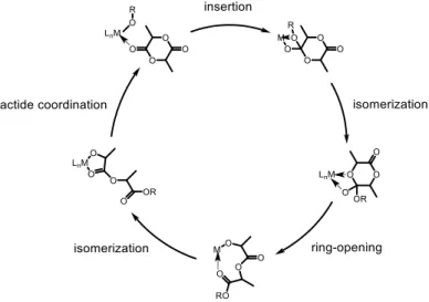
b) Coordination-insertion ROP mechanism: This mechanism, also known as a pseudo–anionic mechanism, is based on metal salts and coordination complexes in which the ring-opening polymerization of lactide is achieved through the coordination of the carbonyl group of the lactide monomer to the open coordination site of the catalyst. This coordination is followed by the insertion of the lactide into the metal-alkoxide bond of the catalyst resulting in the formation of a new alkoxide chain on the metal center. This new chain now acts as an initiator for the next lactide (Figure 1.12).39 Catalysts applied in a coordination-insertion mechanism provide the highest degree of control during polymerization, due to the tight metal-centered transition states causing the ligand system to have a direct effect on transition state energies.
Figure 1.12. Coordination-insertion ROP mechanism.
c) Activated monomer ROP mechanism: This mechanism is very similar to the coordination-insertion mechanism; the only difference is the absence of an initiating group (alkoxide). Thus the reaction requires the addition of an external alcohol. In this polymerization, the lactide monomer coordinates to the Lewis–acidic metal center and is attacked by an external alcohol, leading to the opening of the lactide cycle. Typically, polymerizations are performed at high temperature (>130 ºC) in the absence of solvent (Scheme 1.2). Catalysts for an activated monomer mechanism are the most stable compared to the other three ROP mechanisms discussed, and can polymerize lactide in the presence of water and possibly lactic acid.
Scheme 1.2. Activated monomer ROP mechanism.
d) Organocatalytic ROP mechanism: Organocatalysts are a group of small organic molecules applied for the ROP of lactide. The mechanism is similar to anionic polymerization and can be combined with an activated monomer mechanism. N-heterocyclic carbenes (NHCs) are one of the most popular organocatalysts used to date.40