HAL Id: hal-01076845
https://hal.archives-ouvertes.fr/hal-01076845
Submitted on 14 Jan 2015
HAL is a multi-disciplinary open access archive for the deposit and dissemination of sci-entific research documents, whether they are pub-lished or not. The documents may come from teaching and research institutions in France or abroad, or from public or private research centers.
L’archive ouverte pluridisciplinaire HAL, est destinée au dépôt et à la diffusion de documents scientifiques de niveau recherche, publiés ou non, émanant des établissements d’enseignement et de recherche français ou étrangers, des laboratoires publics ou privés.
beam with a Fresnel bi-prism
Olivier Emile, Janine Emile, Christian Brousseau
To cite this version:
Olivier Emile, Janine Emile, Christian Brousseau. Determination of the topological charge of a twisted beam with a Fresnel bi-prism. Journal of Optics, Institute of Physics (IOP), 2014, Journal of Optics, 16 (12), pp.125703. �10.1088/2040-8978/16/12/125703�. �hal-01076845�
beam with a Fresnel bi-prism.
Olivier Emile1
, Janine Emile2
, Christian Brousseau3
1
LPL, URU 435 Universit´e de Rennes I, 35042 Rennes Cedex, France.
2
IPR, UMR CNRS 6251, Universit´e de Rennes I, 35042 Rennes Cedex, France.
3
IETR, UMR CNRS 6164, Universit´e de Rennes I, 35042 Rennes Cedex, France. E-mail: olivier.emile@univ-rennes1.fr
Abstract. The self-interference pattern of a Laguerre Gaussian beam using a Fresnel bi-prism is shown to be very different from what could be expected from a usual laser beam. Actually it resembles the interference pattern that could be obtained using a double slit experiment. The interferences are shifted and the topological charge and its sign can be readily determined considering the shift order of the pattern only. However, since there is no diffraction nor absorption loses unlike in a double slit interference, such a set up could be used even for low power twisted beams or beams with high topological charge. Even fractional topological charges could be determined with an absolute precision of 0.05.
PACS numbers: 42.50.Tx, 42.87.Bg, 42.50.Xa, 42.25.Hz
Keywords: Fresnel bi-prism, interference, twisted beams, topological charge determination.
1. Introduction
Young’s double slit experiment is one of the most popular demonstrations of the wave nature of light [1, 2]. However contemporaries of Thomas Young raised objections that his results could simply represent diffraction effects from the edges of the slits [3]. Indeed, his results came from the superposition of interference and diffraction phenomena. His findings finally achieved widespread acceptance after Fresnel’s work [4]. Especially, the experience using a bi-prism to produce interferences achieved the same interference pattern but without the problem of diffraction. Actually, in general and particularly in optics, interferences are the most accurate way to probe the phase variation of a wave [5]. This can be either performed using a reference beam, or with a single beam interfering with itself using a wavefront splitting. The use of interferences is specially useful to investigate and probe ”twisted waves” where the wave front is twisting along the direction of propagation [6, 7, 8, 9]. Indeed, the correct determination of the orbital angular content of a beam of light still remains a challenging issue [10]. Several techniques can be applied such as the direct topological charge determination by torque measurements [11, 12], or the measurement of the rotational Doppler shift [13], or operation of the mode creation optics in reverse. Yet, interference measurement is the most popular scheme. A recent review on this can be found in [14]. So far, the interference with a plane wave is one of the interference techniques [15, 16, 17, 18] to characterize twisted beam. However beam interfering with itself is most widely used, in particular experiments using a triangle diffraction pattern [19, 20, 21, 22], or techniques adapted from it for example with hexagonal aperture [23], annular aperture [24] or multi points interferometer [25, 26]. Nevertheless, Young’s double slit experiment has been recently shown to be a powerful and easy to handle alternative [27, 28, 29, 30, 31] to probe twisted beams. Curiously, in nearly all the cases of beam interfering with itself, diffraction is used to split the wavefront. Due to diffraction, this thus leads to loses in the input signal that may be detrimental in low power incoming beams. One may then wonder whether is it possible to implement a Fresnel bi-prism experiment type, that splits the wavefront in two parts without any losses, to probe twisted beams. The aim of this article is then to investigate the potentialities of Fresnel bi-prism to measure the topological charge of a Laguerre Gaussian (LG) beam with integer and even fractional topological charge.
2. Experimental set up
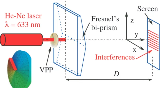
The experimental set up is sketched in figure 1. The twisted beams are generated from the fundamental beam of a red He-Ne laser (λ = 633 nm, Melles Griot, output power P=1 mW) that passes through a vortex phase plate [32] (RC Photonics) adapted for λr = 633 nm. Absolute topological charges, also called beam order or azimuthal number or winding number, can be chosen from ℓ = 0 to ℓ = 5 by choosing the corresponding vortex phase plate. By reversing the plate one can also change the sign of the topological
charge.
VPP
D
Screen
He-Ne laser
λ
= 633 nm
x
z
Fresnel s
bi-prism
Interferences
y
Figure 1. Experimental set up. VPP: Vortex Phase Plate. D: distance between the Fresnel bi-prism and the screen. The vortex phase plate has a variable thickness that induces a phase variation adapted to the laser wavelength in order to generate a LG beam.
The twisted beam is here a LG beam, but the experiment could be implemented for any twisted beam. A telescope can adjust the divergence and the size of the beam, before impinging on the Fresnel bi-prism, in order to maximize the contrast of the fringes. The Fresnel bi-prism has base angle of 0.3o
each and refractive index equal to n = 1.5. The top of the prism is aligned with the height discontinuity of the spiral phase plate. Pictures of the interference patterns are taken on a screen at a distance D = 2 m with a camera.
3. Theoretical considerations
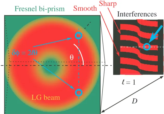
On a plane perpendicular to the direction of propagation, the phase ψ of the twisted beam is not uniform, as for usual plane waves. It varies from 0 to 2ℓπ as one makes one complete turn around the direction of propagation [6, 7, 8, 9], ℓ being the topological charge of the beam. It writes ψ(θ) = ℓθ, where θ is the usual polar coordinate (see figure 2). Fresnel’s bi-prism splits the wave front in two equal parts, leading to two equivalent virtual sources that interfere. At a distance D, when the top of the prism is aligned with the center of the beam, the two beams that interfere on the x axis travel exactly the same distance after being refracted from the prism. In the case of a plane wave the
two beam should lead to constructive interferences on the x axis. However, with twisted LG beams, the fringes are shifted along the x axis. The phase difference equals to
δφ = ψ(θ) − ψ(−θ) = 2ℓθ (1)
As one moves along the x axis the corresponding angle θ varies from 0 to π, thus δφ varies continuously from 0 to 2ℓπ. Consequently, the fringes are twisted with a shift corresponding to ℓ fringe order. The reasoning is rigorously analogous to the one carried in [29] for Young’s double slit, as well as the associated consequences. As one moves into the z direction, the two interfering beams have a phase difference variation that is smoother, however, it still varies continuously from 0 to 2ℓπ. Thus the twist variation of the fringes is also smoother but the shift still corresponds to ℓ fringe order (see figure 2). In principle, it could be possible to change the angle of the prism to optimize the fringe visibility. It should thus be possible to unambiguously determine the topological charge ℓ of a LG beam using a Fresnel bi-prism. In principle, such an experiment should also give the sign of ℓ.
Implicitly, up to now, we have considered LG beams with zero radial index number. For LG beams with non zero radial index numbers [33], on the center on the interference pattern, since both interfering paths are shifted by the same phase, the pattern is the same whatever the radial number. Then the radial index has no influence on the interference pattern. However, It could be separately deduced from the number of nodes on the radial intensity distribution. Thus the Fresnel bi-prism can precisely measure the azimuthal index (or the topological charge) alone.
4. Experimental results.
4.1. Determination of the absolute value of ℓ
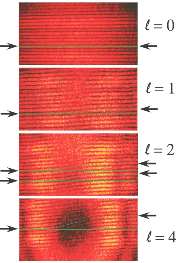
Figure 3 shows several pictures of the interference pattern obtained for different values of ℓ. On the top of the figure, one recognizes the usual interference pattern for a Fresnel bi-prism for a plane wave (i.e. with ℓ = 0). In particular the fringes are straight parallel lines. However, for twisted beams (see following pictures), the interference fringes are dramatically changed. The pattern does not correspond to straight lines any more. The fringes are distorted. However, from one end to the other, the fringes are shifted by an integer number of fringes. The order of their shift corresponds to the topological charge ℓ of the twisted beam. The fringes of the ℓ = 1 beam have been shifted by one interference order, the ℓ = 4 has been shifted by four interference orders (see figure 3).
The topological charge can thus be clearly and readily determined, even with the naked eye. The results resemble the one that have been obtained for Young’s double slit experiment with twisted beams [29]. However, there is no power lost in absorption or in diffraction unlike in a Young type experiment. Indeed in a Young type experiment the wave front splitting is achieved via the diffraction by the two slits that induce losses, whereas the Fresnel bi-prism creates two virtual sources based on diffraction. All the optical power participates to the interferences. Then, the experiment can be carried out
θ
δφ
= 2
l
θ
l=1
LG beam
D
Fresnel bi-prism
Interferences
l = 1
Sharp
Smooth
Figure 2. Schematic of the phase of the LG beam impinging on the Fresnel bi-prism. Two corresponding points have a phase difference equal to δφ = 2ℓθ. This leads to a twisted interference pattern at the corresponding position. One could notice that away front the center of the beam, the fringe variation is smoother.
with very low optical power. For example we have attenuated the optical beam by more than four decades. The fringes can be still detected with a 0.02 µW laser power and a sensitive CCD camera (Thorlabs DCU224) for a ℓ = 1. Besides, the topological charge can be more easily detected for high order beams than for a double slit experiment, since there is more optical power especially in close to the vortex zone. Finally, if the axis propagation is not perfectly aligned with the top of the prism, the fringes twist is smoothed but the shift still corresponds to the topological charge, as can be seen on figure 3 for ℓ = 2.
4.2. Determination of the sign of ℓ
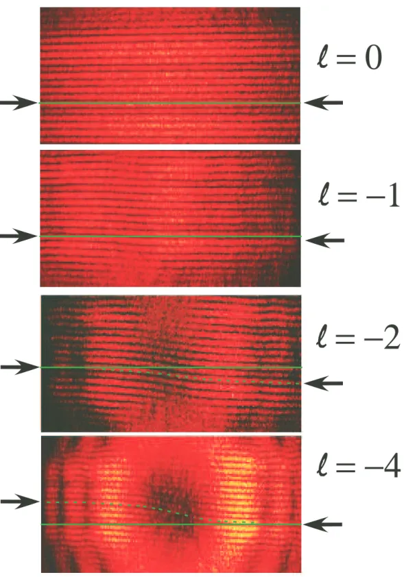
According to equation 1, the twist order could both determine the amplitude and the sign of the topological charge. Let us then change the sign of the topological charge just by reversing the spiral phase plate of figure 1. The sign of the corresponding topological charge should change accordingly. The pictures of the interference patterns are shown on figure 4. They correspond to the same absolute value as the one of figure 3, only the sign has been changed. Clearly the direction of the twist has been reversed. The fringes are now bended downwards, which correspond to a negative value of the topological
l
= 4
l
= 2
l
= 1
l
= 0
Figure 3. Fresnel bi-prism interference patterns. Twisted interference patterns for beams with ℓ = 0, ℓ = 1, ℓ = 2, and ℓ = 4. The shift of the interference pattern determines the topological charge ℓ. The green line is a guide for the eye showing the zero twist. The green dotted line follows the variation of the fringe. The black arrows indicate the fringe order shift. For ℓ = 2, the fringe variation is smoother on the top than on the bottom.
charge, the absolute value of the twist being unchanged. We are also able to determine unambiguously the sign of the topological charge. The fringe contrast is still high, with the same magnitude, as well as the intensity of the fringes.
5. Discussion
Actually, this set up shares the advantages of Young’s double slit experiment and not the drawbacks. In particular, it is a quick and easy to handle tool to measure the topological charge ℓ of a twisted beam. The twist order of the fringes can be readily seen on a screen with the naked eye. However, in contrast to all interfering techniques based on diffraction, since there is no power lost, it could also be applied to low power twisted beam. One has only to count the number of twists of the interference pattern, following the whole interference pattern. However, one cannot determine the topological charge of the beam considering only one end and the other end of the fringes, since the fringes are shifted by an integer number order of fringes. From one end of the fringes to the other, the phase variation corresponds to θ = π, leading to δφ = 2ℓθ = 2ℓπ in equation 1.
5.1. Fractional topological charge
According to this equation (equation 1), one may then wonder whether is it possible to measure the topological charge of twisted beams with fractional topological charges [34, 35, 36, 37]. In this kind of beam with non-integer topological charges, the phase varies from 0 to 2ℓπ as one makes one complete turn around the direction of propagation, ℓ being a fractional number. This leads to a discontinuity in the phase variation and a discontinuity in the beam intensity as well [35]. Actually, these fractional topological charges are difficult to evaluate [21].
In the present work, such fractional topological charges have been realized still using the spiral phase plate. While keeping the spiral phase plate that is adapted to λr = 633 nm and for ℓ = +1, we have changed the wavelength of the laser. We have aligned the phase discontinuity with the top of the prism, in the horizontal direction. This corresponds in figure 1 to a conter clock wise rotation of 30◦of the spiral phase plate. Whereas the two interfering passes are in phase and leads to constructive interferences on the x axis on one end of the interferences of the beam side of the beam. On the other end this leads to a phase difference
δφ = ψ(−π) − ψ(π) = −2ℓπ (2) ℓ being fractional. This phase difference is related to the height of the step of the spiral phase plate e (e = 420 nm) and to the index of refraction n of the deposited polymer on the substrate plate. The extra phase shift due to the step then equals (2π/λ)ne. Thus the phase shift can be re-expressed
δφ = −2ℓπ = −2π
l
= −4
l
= −2
l
= −1
l
= 0
Figure 4. Fresnel bi-prism interference patterns. Twisted interference patterns for beams with ℓ = 0, ℓ = −1, ℓ = −2, and ℓ = −4. The shift of the interference pattern determines the topological charge ℓ and its sign. The green line is a guide for the eye showing the zero twist. The green dotted line shows the fringe variation. The black arrows indicate the fringe order shift.
Then, assuming the same optical index of the polymer for λr = 633 nm and for the other wavelength λo, the shift of the fringes then equals λr/λo.
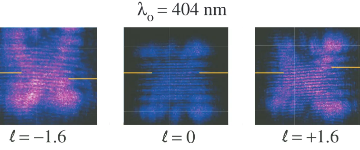
l
= 0
l
= −1.6
l
= +1.6
λ
o
= 404 nm
Figure 5. Interference pattern of a blue twisted beam. The measured fractional topological charge are ℓ = −1.6, ℓ = 0 and ℓ = +1.6. The yellow lines indicate the constructive interference on each end of the pattern.
We have first performed the experiment using a violet diode laser at λo = 404 nm (Ovio Instrument P = 1 mW), see figure 5. Since the phase plate is adapted for λr = 633 nm, the topological charge must be a non integer. The shift and the topological charge are expected to be ℓ = 633/404 = 1.56. Experimentally we measure ℓ = 1.60 ± 0.05. Since the optical index is slightly higher at λo = 404 nm than at λr = 633 nm, the result is in very good agreement with the expected value. The experiment can be adapted for any fractional topological charges, either with values close to zero, or with high values, or with negative values.
5.2. Precision of the determination of the fractional topological charge
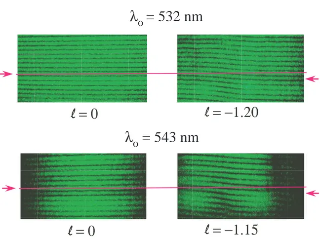
Actually, since there is no optical power losses using Fresnel bi-prism, the interference patterns are clean and sharp, even for fractional topological charges. Is it then possible to discriminate close fractional topological charges? What would be the precision? To that purpose, we have carried out the experiment described in of the preceding paragraph with two green lasers, one at a wavelength of λo1 = 532 nm (Ovio instrument, P = 2 mW), the other using a He-Ne laser at a wavelength of λo2 = 543 nm (Mlles Griot, P = 0.5 mW). The Fresnel bi-prism interferences are shown in figure 6. The time exposition of the picture is the same for the two lasers. The difference in intensity is due to the power difference between the lasers.
The expected fractional topological charge, according to equation 3, are ℓ1 = 633/532 = +1.19 for λo1 = 532 nm, and ℓ2 = 633/543 = +1.16, for λo2 = 543 nm. Experimentally, we find ℓ1 = +1.20 ± 0.05 and ℓ2 = +1.15 ± 0.05, which is in very good agreement with the expected values. But most importantly we can notice that
λ
o
= 532 nm
l
= 0
l = −1.20
l = 0
l
= −1.15
λ
o
= 543 nm
Figure 6. Interference pattern of two green lasers using Fresnel bi-prism. The measured fractional topological charge are ℓ = 1.20, and ℓ = +1.15. The red lines indicates the interference for the ℓ = 0.
although the two fractional topological charges are very close (δℓ = 0.03) we are able to discriminate them; ℓ1 is clearly bigger than ℓ2.
6. Conclusion
We have shown that the Fresnel bi-prism experiment is a quick and easy to set-up experiment to precisely measure, even with the naked eye, not only the value of the topological charge but the sign of it too. Since there is no power lost in absorption or in diffraction effects, contrarily to interference techniques that use diffraction, this technique could be readily implemented on very faint optical powers, like in diffracted twisted beams [38, 39]. On the other end, such interferences could also appear in real transmission experiments [40, 41, 42] using twisted beams when the direct signal and reflections for example in the surface of water or multi way signals can interfere. This could lead to unexpected perturbed reception signals, with twisted interferences.
Besides, the Fresnel bi-prism enables the precise determination of fractional topological charges, with an absolute precision of 0.05. It thus can be useful in the guiding and transport of microparticles where the use of fractional topological charge
have been shown to avoid the smooth rotation of the particle [43]. It could also have practical applications in entanglement experiments using fractional orbital momentum [37, 44, 45].
Acknowledgments
We acknowledge technical support from J.R. Th´ebault, and valuable discussion with L. Mouret.
References
[1] Young T 1804 Phil. Trans. R. Soc. Lond. A 94 1
[2] Feynman RP, Leighton R and Sands M 1965 The Feynman lecture on physics. Vol. 3 (Addison-Wesley, Massachusetts)
[3] Hecht E 2001 Optics, 4th
Ed. (Addison-Wesley)
[4] Fresnel A 1866 Œuvres compl`etes d’Augustin Fresnel: Th´eorie de la lumi`ere (Imprimerie imp´eriale, Paris)
[5] Hariharan P 2007 Basics of interferometry (Academic Press, London)
[6] Allen L, Beijersbergen MW, Spreeuw RJC and Woerdman JP 1992 Phys. Rev. A 45 8185 [7] Opical Angular momentum Allen L, Barnet SM and Padgett MJ Edts. 2003 (IOP Publishing Ltd,
London)
[8] Molina-Terriza G, Torres JP and Torner L 2007 Nature Phys. 3 305 [9] Padgett MJ and Bowman R 2011 Nat. Photonics 5 343
[10] Quarsim H, Miatto FM, Torres JP, Karimi E and Boyd RW 2014 J. Opt. Soc. Am. B 31 A20 [11] Demore CEM, Yang ZY, Volovick A, Cochran S, MacDonald MP and Spalding GC 2012 Phys.
Rev. Lett. 108194301
[12] Emile O, Brousseau C, Emile J, Niemiec R, Madhjoubi K and Thid´e B 2014 Phys. Rev. Lett. 112 053902
[13] Courtial J, Dholakia K, Robertson DA, Allen L, Padgett MJ 1998 Phys. Rev. Lett. 80 3217 [14] Lavery MPJ and Padgett MJ in Opical Angular momentum Andrews DL and Babiker M Edts.
2012 (Cambridge University Press, London)
[15] Bazhenov VYu, Soskin MS and Vasnetsov MV 1992 J. Mod. Opt. 39 985 [16] Harris M, Hill CA, Tapster PR and Vaughan JM 1994 Phys. Rev. A 49 3119 [17] Padgett M, Arlt J, Simpson N and Allen L 1996 Am. J. Phys. 49 3119 [18] Vickers J, Burch M, Vyas R and Sing S 2008 J. Opt. Soc. Am. A 25 823
[19] Hickmann JM, Fonseca EJS, Soares WC and Ch´avez-Cerda S 2010 Phys. Rev. Lett. 105 053904 [20] Anderson ME, Bigman H, de Araujo LEE and Chaloupka JL 2012 J. Opt. Soc. Am. B 29 1968 [21] Mourka A, Baumgartl J, Shanor C, Dholakia K and Wright EM 2011 Opt. Express 19 5760 [22] Hickmann JM, Fonseca EJS and Jesus-Silva AJ 2011 EPL 96 64006
[23] Liu Y and Pu P 2011 Opt. Commun. 284 2424
[24] Guo CS, Lu LL and Wang HT 2009 Opt. Lett. 34 3686
[25] Berkhout GCG and Beijersbergen MW 2009 J. Opt. A. 11 094021 [26] Guo C-S Yue S-J and Wei G-X 2009 Appl. Phys. Lett 94 231104 [27] Sztul HI and Alfano RR 2006 Opt. Lett. 31 999
[28] Liu R, Long J, Wang F, Wang Y, Zhang P, Gao H and Li F 2013 J. Opt. 15 125712 [29] Emile O and Emile J 2014 Appl. Phys. B DOI 10.1007/s00340-014-5859-1
[30] Emile O, Le Meur M and Emile J 2014 Phys. Rev. A 89 013846 [31] Zhou H, Yan S, Dong J and Zhang X 2014 Opt. Let. 39 3173
[33] Karimi E, Boyd RW, de la Hoz P, de Guise H, ˇReh´aˇcek J, Hradil Z, Aiello A, Leuchs G and S´anchez-Soto LL 2014 Phys. Rev. A 89 063813
[34] Leach J, Yao E and Padgett MJ 2004 New J. Phys. 6 71 [35] Berry MV 2004 J. Opt. A 6 259
[36] Basistij IV, Pas’ko VA, Slyusar VV, Soskin MS and Vasnetsov MV 2004 J. Opt. A 6 S166 [37] G¨otte JB, O’Hollran K, Preece D, Flossman F, Franke-Arnold S, Barnett SM and Padgett MJ
2008 Opt. Express. 16 993
[38] Cui HX, Wang XL, Gu B, li YN,Chen J and Wang HT 2012 J. Opt 14 055707
[39] Emile O, Voisin A, Niemiec R, Viaris de Lesegno B, Pruvost L, Ropars G, Emile J and Brousseau C 2013 EPL 101 54005
[40] Tamburini F, Mari E, Sponselli A, Thid´e B, Bianchini A and Romato F 2012 New J. Phys. 14 033001
[41] Wang J, Yang JY, Fazal IM, Ahmed N, Yan Y, Huang H, Ren Y, Yue Y, Dolinar S, Tur M and Willner AE 2012 Nat. Photonics 6 488
[42] Krenn M, Fickler R, Fink M, Handsteiner J, Malik M, Scheidl T, Ursin R and Zeilinger A 2014
Twisted light communication through turbulent air accross Vienna ArXiv:1402.2602 [43] Tao SH, Yuan XC, Lin J, Peng X and Niu HB 2005 Opt. Express 13 7726
[44] Oemrawsingh SS, Ma X, Voigt D, Aiello A, Eliel ER, ’t Hoff GW and Woerdman JP 2005 Phys.
Rev. Lett. 9520501