HAL Id: hal-00616713
https://hal.archives-ouvertes.fr/hal-00616713v2
Submitted on 24 Aug 2011
HAL is a multi-disciplinary open access
archive for the deposit and dissemination of
sci-entific research documents, whether they are
pub-lished or not. The documents may come from
teaching and research institutions in France or
abroad, or from public or private research centers.
L’archive ouverte pluridisciplinaire HAL, est
destinée au dépôt et à la diffusion de documents
scientifiques de niveau recherche, publiés ou non,
émanant des établissements d’enseignement et de
recherche français ou étrangers, des laboratoires
publics ou privés.
New stereoscopic video shooting rule based on
stereoscopic distortion parameters and comfortable
viewing zone
Wei Chen, Jérôme Fournier, Marcus Barkowsky, Patrick Le Callet
To cite this version:
Wei Chen, Jérôme Fournier, Marcus Barkowsky, Patrick Le Callet. New stereoscopic video shooting
rule based on stereoscopic distortion parameters and comfortable viewing zone. Stereoscopic Displays
and Applications XXII, SPIE 2011, Jan 2011, San Francisco, United States. pp.SPIE 7863, 78631O,
�10.1117/12.872332�. �hal-00616713v2�
New stereoscopic video shooting rule based on stereoscopic distortion
parameters and comfortable viewing zone
Wei Chen*
ab, Jérôme Fournier
a, Marcus Barkowsky
b, Patrick Le Callet
ba
Orange labs, France télécom, 4 rue du Clos Courtel, 35512 Cesson-Sevigne, France
b
IRCCyN UMR 6597 CNRS, Ecole Polytechnique de l’Université de Nantes, rue Christian Pauc, La
Chantrerie 44306 Nantes, France
ABSTRACT
Human binocular depth perception, the most important element brought by 3DTV, is proved to be closely connected to not only the content acquisition (camera focal length, camera baseline and etc.) but also the viewing environment (viewing distance, screen size and etc.). Conventional 3D stereography rule in the literature usually consider the general viewing condition and basic human factors to guide the content acquisition, such as assuming human inter-pupil baseline as the maximum disparity. A lot of new elements or problems of stereoscopic viewing was not considered or precisely defined so that advanced shooting rule is needed to guarantee the overall quality of stereoscopic video. In this paper, we proposed a new stereoscopic video shooting rule considering two most important issues in 3DTV: stereoscopic distortion and comfortable viewing zone. Firstly, a mathematic model mapping the camera space to visualization space is established in order to geometrically estimate the stereoscopic depth distortion. Depth and shape distortion factors are defined and used to describe the stereoscopic distortion. Secondly, comfortable viewing zone (or Depth of focus) is considered to reduce the problem of visual discomfort and visual fatigue. The new shooting rule is to optimize the camera parameters (focal length, camera baseline and etc.) in order to control depth and shape distortion and also guarantee that the perceived scene is located in comfortable viewing zone as possible. However, in some scenarios, the above two conditions cannot be fulfill simultaneously, even sometimes contradict with each other so that priority should be decided. In this paper, experimental stereoscopic synthetic content generation with various sets of camera parameters and various sets of scenes representing different depth range are presented. Justification of the proposed new shooting rule is based on 3D concepts (depth rendering, visual comfort and visual experience) subjective video assessment. The results of this study will provide a new method to propose camera parameters based on management of new criteria (shape distortion and depth of focus) in order to produce optimized stereoscopic images and videos.
Keywords: Stereoscopic video shooting rule, stereoscopic distortion, comfortable viewing zone, subjective assessment,
depth rendering, visual comfort, visual experience
1. INTRODUCTION
Following the success of HDTV standard, wherever in industry or academic society, stereoscopic television broadcasting service is believed as the most possible next generation service. The most important element which is brought by the 3DTV technique is the binocular depth perception. It enhances the human immersive feeling in image and video, while it also brings some side effect e.g. eye strain and cardboard effect if human factors are not well considered.
Two main issues concerning the binocular depth perception are stereoscopic distortion and visual comfort. For stereoscopic distortion, several research works had proved that camera parameters (focal length, camera baseline and etc.) as well as final visualization parameters (viewing distance, screen size and etc.) directly affect the final perceived depth. A. Woods[1] established the geometry model of stereoscopic video systems and analyzed the origins, characteristics and effects of image distortion in stereoscopic video system. N. Holliman[2] explained how to control the perceived depth by adapting the stereoscopic camera parameters in order to avoid excessive perceived depth. The same author in [3] proposed an algorithm for stereoscopic image capture in order to map perceived depth to region of interest. For visual comfort, earlier in the last 90s, S. Pastoor[4] discussed about the human factors e.g. disparity range and concluded that visual comfort for stereoscopic video system is a key factor related to its success of competing with 2D _________________________________________
systems. In [5], the author proposed the traditional visual comfort threshold of 70 arcmin for disparities based on subjective assessment. 0.3 diopter(reciprocal value of distance) and 60arcmin was suggested in paper[6] as limits of Depth of focus (DoF) and binocular disparity. In ITU-R BT.1438[7], the stereoscopic pictures are suggested to be displayed within the depth of field of the human eye which is ±0.3 diopter. ±0.2 diopter was suggested in [8] since visual fatigue was clearly induced when images were displayed outside the corresponding range of depth of focus, and even within this range, visual fatigue was induced if the image were moved in depth according to a step pulse function. In professional stereoscopic shooting activities, the 1/30TH rule of thumb of 3D[9], which stipulates that the inter-axial distance should be 1/30th of the distance from the camera to the first foreground object, is suggested and widely used in stereo photography. However, it is empirical method and only can contain a rough estimation and suggestion for camera parameters.
In this paper, we aim to propose a new advanced stereoscopic video shooting rule considering the two elements: stereoscopic distortion and visual comfort. To achieve this goal, in Section 2, firstly we establish a geometry model mapping the camera space to the final visualization space. Mathematical definition of stereoscopic distortion including depth distortion factor and shape distortion factor is proposed. Comfortable viewing zone is also defined in order to avoid visual discomfort and visual fatigue. Two basic shooting rules are defined: Optimal Rule 1 optimize the camera parameters to control the perceived depth and avoid shape distortion for the region of interest objects; Optimal Rule 2 optimize the camera parameters to control all the perceived scene depth range within the comfortable viewing zone. And the combination and priority of these two basic rules is that if the Rule 1 and Rule 2 cannot be fulfilled simultaneously, the Rule 2 is prior to Rule 1. The proposed optimal shooting rule can be summarized and simplified as for example to adapt the camera parameters to guarantee the perceived whole scene depth range located in the comfortable viewing zone and then to optimized the object perceived shape in the region of interested point. In order to justify the proposed shooting rule, in Section 3, we defined four different scene categories based on the depth range and depth cue. Based on this scene categorization, we have selected five scenes from an open source animation movie and use different camera parameters to regenerate the scene into stereoscopic images. A 3D concepts based subjective quality assessment section is organized after the production of stereoscopic images. In Section 4, we present the methodology used in this assessment as well as the analysis of the final results. Finally, section 5 summarizes the major findings and proposed direction of the use and extension of the proposed shooting rule.
2. NEW STEREOSCOPIC SHOOTING RULE
Parallel camera configuration was proved to be able to maintain linearity during the conversion from real space to stereoscopic images[10] resulting in avoiding to produce puppet theatre effect[11] and also the vertical disparity[1]. All the subsequent camera is default parallel camera configure. In this section, a simplified geometry model similar to the A. Woods[1] is established, stereoscopic distortion factor concerning shape distortion and comfortable viewing zone will be defined, respectively. Secondly, optimal shooting Rule 1 and 2 is defined and the combination and priority of these two shooting rule is discussed.
2.1 Geometry of Camera space and visualization space
The geometry of parallel camera space and the planar display based visualization space are shown in Figure 1 and Figure 2, respectively. The following variables are used to derive the geometry model mapping the camera space to the final visualization space.
Camera spaces in Figure 1:
f - Focal length of the camera: it is related to the field of view of camera.
b- Inter-Camera baseline: The distance between the first nodal points of the two camera lenses.
,
ccd ccd
w
h
- Camera sensor width and height: the horizontal and vertical size of the camera CDD or CMOS sensor.cov
d
- Convergence distance: The distance from the virtual convergence plane (or zero disparity plane) to the camera focal length plane.ccd
shift - Sensor shift or post-production shift: this is the distance by which the center of each image senor has been
cov
2
ccdfb
shift
d
=
(1)( , , )x y z : The location of a point in camera space (in front of the camera).
(xCL,yCL)(xCR,yCR): The point in physical space maps into the camera sensor, the location of left and right image points in respective camera sensors.
( , ) Object
x z
Convergence Screen Plane
b
f
ccd w c o vd
z
+
x
+
CL x + +xC R cc d s h ift c c d hz
+
y
+
, CL CR y y + + ( , ) Object y z( )
b
( )
a
Figure 1. Geometry of Parallel camera space (a) xz plane view (b) yz plane view
Visualization space in Figure 2: screen
W
H
screen- Screen Width: the horizontal and vertical size of the screen.V - Viewing distance: The distance from the observer’s eye to display plane.
B
- Inter-pupil baseline: The distance between the observers’ left eye and right eye, for adult, typically 65mm.,
(XSLXSL)(XSR,XSR): The location of the left and right image points in the display plane.
(X Y Z, , ): The location of the point in visualization space, as stereoscopically viewed by the observer when displayed
on the screen.
Other system variables:
M
- Frame Magnification factor,M
=
W
screen/
w
ccdThe geometry relationship of stereoscopic video system can be mapping as below:
,
Camera space ( , , )x y z →CCD sensor (xCL,yCL)(xCR,yCR)→Display plane (XSLYSL)(XSR,YSR)→Visualization Space( , , )X Y Z The overall transform from the camera space to the visualization space can be summarized as the below equations:
-cov (1 ) MBfx X z Bz Mfb d = + (2) -cov (1 ) MBfy Y z Bz Mfb d = + (3) -cov (1 ) VBz Z z Bz Mfb d = + (4)
( , ) Object X Z V B s c r e e n W
Z
+
X + SL SR Y =Y ( , ) Object Y Z s c r e e n H Z +Y
+
SR X SL X( )
a
( )
b
Figure 2. Geometry of visualization space (a)
XZ
plan view (b)YZ
plan view2.2 Stereoscopic distortion
,
, x y z
D D D are defined as the derivative of the X Y Z, , in the final visualization space with respect to x y z, , in the
camera space. They can be derived from the equation (2) to (4) as below:
-cov (1 ) x dX MBf D z dx Bz Mfb d = = + (5) -cov (1 ) y dY MBf D z dy Bz Mfb d = = + (6) - 2 cov [( (1 )] z dZ VBMfb D z dz Bz Mfb d = = + (7)
As shown in equation (5) and (6),
D
xequals to Dy so that 2D shape is kept constant andD
z is a function of z whichcan be used to represent the depth distortion. A new factor representing the 3D shape distortion is defined as
D
s. Itdenotes the changes ratio of
D
zversusD
xas below:cov
(1
)
z s xD
Vb
D
z
D
Bz
Mfb
d
=
=
+
−
(8)When D zs( )equals to one, 3D shape around depth plane z in the visualization space maintain the same as in the camera space. In the following of the paper, stereoscopic 3D shape distortion factor
D
sis used as the main indicator of thestereoscopic distortion.
2.3 Comfortable viewing zone
In the paper[12], comfortable viewing zone is a perceptual range where binocular fusion is possible and blur is not perceived so that stereoscopic visual comfort should be maintain. Combing the limit of disparity and DoF, generally in this paper, ±0.2 diopter can be used as a general limit as the comfortable viewing zone as shown in Figure 3. We can derive ZComfortf as the limit of the absolute foreground distance in the visualization space and
Comfort b
Z as the limit of the absolute background distance:
1 1 1 , if 1 1 , 1 , if Comfort Comfort f b d V DoF DoF Z V Z V DoF V V DoF − − − < − = − = + ∞ ≥ (9)
( , ) Object X Z
V
Z
+
X
+
Comfort fZ
Comfort bZ
Figure 3. Comfortable viewing zone (DoF=0.2D)
2.4 Optimal shooting rule
From Equation (8), stereoscopic shape distortion factor Dsis not a linear function, only in some extreme cases, e.g. orthostereoscopic[13], the conversion ratio of the camera space to visualization space is kept to be one only in the below condition: cov cov
if
b
B f
,
d
,
V
d
, then
D
s1
M
=
=
=
=
(10)However, in practical application, the above conditions are hard to fulfill. For instances, stereographer are used to select their own camera focal length based on the field of view of camera. Viewing distance is normally depending on the final display size and resolution. i.e. there are a lot of constrains considering the camera parameter and the visualization parameters which results in the difficulties to keep the perceived depth space to be linear. The concept of Region of Interest (RoI) is often used in the image and video processing in order to do the conditional optimization. Here, zRoIis defined as the depth plane locating the RoI object and the basic optimal shooting Rule 1 can be defined as below:
(1) Adapt the changeable parameters to guarantee the shape distortion factors RoI s
D (D in the plane of RoI s zRoI )
to approximate one as much as possible.
Furthermore, comfortable viewing zone( Comfort, Comfort)
f b
Z Z which is defined by the Equation (8) is the other important factor we need to take into consideration. If the shooting scene depth range is defined in ( scene, scene)
f b
z z , from Equation (4), scene perceived depth range can be computed as ( scene, scene)
f b
Z Z . Only if
( scene, scene) ( Comfort, Comfort)
f b f b
Z Z ∈ Z Z (11)
then visual comfort can be guaranteed. There are two methods to fulfilled the equation (11)’s condition. The first that is that assuming that the camera parameter and visualization parameter is known and unchangeable, only scene parameters are adaptable. From equation (4), we can derive its inverse function:
cov cov
(
1)
Mfbd
z
V
Bd
Mfb
Z
=
−
+
(12)Based on this equation, we can get( Comfort, Comfort) ( Comfort, Comfort)
f b f b
Z Z → z z which means that if the scene range can be
limited within the comfortable depth zone:
Visual comfort condition can be fulfilled. However, in most cases, the director or stereographer are willing to design the scene range freely. So the second method is to adapt the camera parameters (e.g. focal length, convergence distance and camera baseline) to guarantee the perceived scene range to locate within the comfortable viewing zone as Equation (10). Above all, the basic optimal shooting rule 2 can be summarized as below:
(2) Guarantee the perceived scene range ( scene, scene)
f b
Z Z maintain within the comfortable viewing zone
( Comfort, Comfort)
f b
Z Z by adapting the scene parameters or camera parameters.
However, there exists that in some scenarios, the above two basic optimal rules can not assemble each other so that priority should be decided. From the subjective experiments carried out in Orange labs Rennes site, visual comfort problem is more serious than stereoscopic shape distortion in usability oriented applications (television broadcasting, movie and etc.). In this paper, the shooting rule is mainly designed for usability oriented application so that the combination and priority of the two basic optimal rules is defined as below:
(3) When Rule 1 and Rule 2 can not be fulfilled simultaneously, Rule 2 is prior to Rule 1 which means visual comfort is more important than stereoscopic shape distortion.
However, in utility oriented application, e.g. medical and space science stereoscopic viewing, the strategy of priority may be different.
3. STEREOSCOPIC CONTENT GENERATION
In order to justify and better adapt the optimal shooting rules, practical stereoscopic content acquisition or generation is required. In order to avoid the view asymmetry problems such as geometry distortion, colormetric and etc, in this paper, synthetic stereoscopic content generation is implemented. Different depth range scenes are selected from a open source animation project “Big buck bunny”[14] and rendered by Blender software[15].
3.1 Stereoscopic scene categorization and selection
Table 1. The stereoscopic scene categorization
Name Micro space Personal space Action space Vista space
Depth range <1m 1-3m 3-15m >15m
In the paper[16], the depth discrimination function delimit three types of space around the moving observer - personal space, action space and vista space – each served by different sources of depth cue and with different weight. In this paper, we divided the personal space into micro space and personal space in order to precisely distinguish the stereoscopic scene. Then stereoscopic scene can be categorized by depth range as the Table 1.
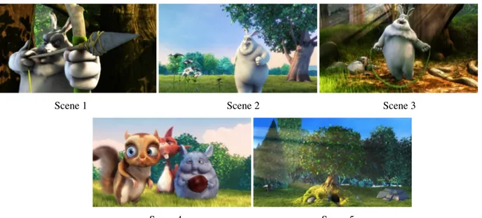
Table 2. Overview of the five scenes and their characteristics
Scene Number scene f z Near plane (m) scene b
z
Far plane(m) RoI z RoI plane(m)Depth space Description
1 0.33 2.4 0.56 Micro space Bunny holding the arrow and bow 2 1.9 17 4.7 Action space Bunny walking from the tree to flower
3 5 10 5 Action space Robe skipping bunny
4 1.1 10 1.5 Personal space Three standing squirrels
5 20 52 30 Vista space A tree and the background forest
Based on the above categorization, five scenes as shown in Figure 4 in the animation “Big buck bunny” are selected which covers all the categories. All the scenes are adapted carefully in order to avoid depth contradiction, e.g. the original scene uses some additional blur to enhance the depth cue however it may contradict with the binocular depth cue. The unit in the Blender software and synthetic scene is setting to meter in order to better simulate the real world shooting. The description of these five scenes is shown in the Table 2. RoI plane is selected manually and the depth
range is defined mainly based on the RoI depth plane. And normally, the converged plane or called zero disparity plane is close to the RoI plane to make the RoI object locate in the display plane.
Scene 1 Scene 2 Scene 3
Scene 4 Scene 5 Figure 4: five selected scenes from “Big buck bunny”
3.2 Acquisition and Post processing
All the images are rendered by Blender software in the resolution of native 1920x1080 pixels. 8 samples anti-aliasing over sampling is enabling to make the edge smooth and all the addition blur effect is disabling to guarantee the nature sharpness. The virtual camera inside Blender is 32mm x 16mm size sensor. A special python plug-in of Blender is developed by Orange labs in order to make the stereoscopic shooting in the Blender software. Two individual virtual cameras with controlled camera parameters are used to shoot the scene. In order to avoid the black border after the post production shift to achieve the converged plane, the extended boarder related to the converged shift is rendered for every image.
The post production is mainly about post-production shift and the stereoscopic format conversion. All the stereoscopic images are saved and transformed in loss-less image format in order to avoid quality degradation.
3.3 Selected Camera parameters
A StereoCalculator Software is developed by Orange labs in order to ease the optimization of camera parameters of shooting and also visualization of stereoscopic depth distortion as well as analysis of comfortable viewing zone. The final visualization display is the Hyundai S465D line-interleaved display assembling with polarized glasses. The native panel resolution is 1920x1080 and the viewing distance is computed to fulfill the 1 min/arc visual acuity threshold of pixel. Camera sensor is the default Blender camera sensor and the camera focal length is fixed for certain scene. The converged distance is set to equal to RoI plane distance. So the only adaptable camera parameter for depth rendering is the camera baseline. The fixed camera parameters are shown in Table 3.
Table 3: Fixed camera parameters
f
(mm) ccd ccdw
×
h
(mm) covd
W
screen×
H
screen(m)V
(m)B
(mm) 24.65(Scene 1), 28.59(Scene 2), 35(Scene 3-5) 32 x 16 =zRoI 1.01 x 0.57 1.82 65For each scene, five different conditions are defined in order to justify the proposed optimal shooting rule: (1) 2D image, the left view of stereoscopic image pair is used as the 2D image;
(2) DoF equals to 0.1 D, which is a conservative value for ensuring the comfortable viewing while possibly generate compressed shape distortion(D <s 1);
(3) DoF equals to 0.2 D, which is suggested in pervious paper[12] based on the study of physiology and psychology research results;
(4) DoF equals to 0.3 D, which is suggested by the ITU-R BT.1438[7]; (5) RoI
s
D equals to 1, which to avoid the shape distortion in the RoI plane.
For condition (2) to (3), each DoF value indicates different levels of comfortable viewing zone ( Comfort, Comfort)
f b
Z Z as well
as different level of shape distortion and camera baselines are adapted to fulfill both the equation (11) and the below equation:
( scene Comfort) or/and ( scene Comfort)
f f b b
Z =Z Z =Z (14)
which guarantee the perceived scene range is locating in the comfortable viewing zone by enlarging or compressing the perceived depth. The condition (5) is following the basic optimal Rule 1 but without considering Rule 2. Camera baselines are calculated to fill the above five condition for five selected scene. They are shown in the Table 4 as well as the calculatedDsRoI:
Table 4. Camera baseline and shape distortion of five different conditions in five scenes
Scene
Num
2D DoF =0.1 DoF =0.2 DoF =0.3 RoI 1
s D = b (mm) RoI s D b (mm) RoI s D b (mm) RoI s D b (mm) RoI s D 1 X 11 0.55 22 1.1 33 1.65 20 1 2 X 43 0.26 85 0.5 145 0.86 168 1 3 X 10⁶ 0.59 213 1.20 319 1.79 178 1 4 X 17 0.31 37 0.69 50 0.93 54 1 5 X 638 0.59 1283 1.2 1930 1.8 1069 1
Compared to the previous research[17, 18], which only use the same group of 10, 20, 30,40, 50cm camera baselines in different depth range, scene acquisition is not correlated to Depth of Focus requirements. Here, DoF values can be used as the indicator of the normalized perceived depth range which can ease the comparison of different camera setting. The optimal condition which fulfills the proposed optimal shooting rule in each scene is shown in bold and underlined in Table 4.
4. SUBJECTIVE QUALITY ASSESSMENT BASED ON 3D EVALUATION CONCEPT
In traditional 2D subjective quality assessment method, generally Image Quality is used as the subjective quality indicator. However, as discussed in the paper[12], additional indicator such as Depth rendering, Naturalness, Presence, Visual Experience, Visual Comfort and etc should be taken into consideration since the additional dimensional – Depth brings to the viewer more perceptual information. In this section, subjective quality assessment based on 3D evaluation concept is used to evaluate the generated stereoscopic content in order to justify the proposed optimal shooting rules.
4.1 Methodology
1) Equipment: The subjective quality assessment was conducted in a test room, which is compliant with the recommendations for subjective evaluation of visual data issued by ITU-R BT.500[19]. As mentioned in the last section, a 46 inch line-interleaved stereoscopic display with a native resolution of 1920x1080 pixels was used as the final visualization terminal. The depth rendering ability of this display had been analyzed in the paper[12] which performs a overall good depth rendering ability. A digital video system (DVS) which can output 1920x1080 HD signal was used.
2) Observers: 28 observers were recruited to participate in this test. All of them are non experts in the audiovisual and
video domain. A vision test was performed on all the testers to determine their visual performance and the potential impact on results. The test includes monocular visual acuity test (distant vision acuity test, near vision acuity test),
hyperopia trend, astigmatic trend, binocular distant vision acuity, dysphoria, fusion, stereoacuity, and color vision. The vision test showed that all the testers were able to perceive binocular depth.
3) Stimuli: The test session was composed of five scenes as shown in Table 2. For each of the scenes five different stimuli had been considered corresponding to different conditions as shown in Table 4 so that there were overall 25 stimuli which were all still stereoscopic image.
4) Procedure: written instructions detailing the task what they had to perform and the attribute they were asked to rate were given to the subjects before the start of the test. These instructions were then reiterated by the experimenter as to ensure the observer understood the task.
Subjective assessment methodology for Video Quality(SAMVIQ)[20] which is derived from the DSCQS for television was used in this test. Considering the 3D evaluation concepts and the test purpose, three new quality indicators were used in this test: (1) Depth rendering, connected to the stereoscopic distortion, which represents the perception of depth; (2) Visual comfort, connected to the comfortable viewing zone, which represents the comfortable viewing level of the image (3) Visual Experience, an overall and multi dimensional perception concept, which represents not only the physical but also the emotional impression of the image. As explained in [21], these three quality indicators may have internal connection and mutual influence with each other so that individual test session is implemented for each quality indicator. The whole test was separated into two experiments. Experiment I included a test session of Depth rendering and a test session of Visual comfort. Half of the test is first Depth rendering and then Visual comfort, the other half is in the reverse order. Experiment II only included a test session of Visual experience and it was organized in a different day of the Experiment I in order to avoid the influence of the experiment I to experiment II.
For each test session, five scenes, which have five stimuli in each scene, were evaluated by the subjects. For each scene, the subject could see all the five stimuli and rate their perceptual opinion. These stimuli were shown as button A, B, C, D, and E can be viewed several times if the subject wished. The buttons were randomly reassigned to stimuli so that the subjects could not identify them. Each stimulus was shown with duration of 7s and the subjects provided their score. Subjects were able to freely modify their score before the end of the test.
5) Outlier detection: The screening of subjects was performed according to the guidelines described in ITU-R
BT.500[19]. For the Experiment I, 5 of the 28 subjects have been discarded as outlier. For Experiment II, 3 of 28 subjects have been discarded. Thus the final result analysis is based on the scores of the non-outlier subjects.
4.2 Result analysis
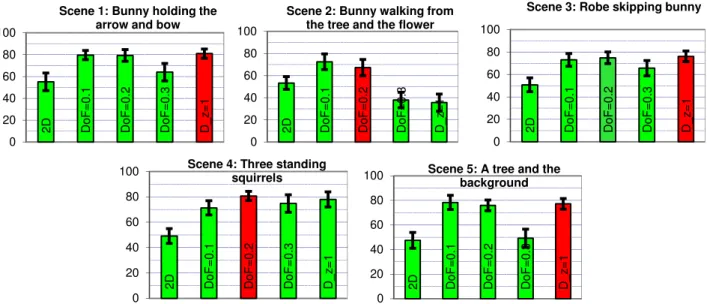
Figure 5. Mean opinion scores and confidence intervals of Depth rendering vs. five different conditions for the different scenes (Red/deep color tube is the selected optimal condition)
2 D DoF = 0 .1 D o F = 0 .2 D o F = 0 .3 D _ z = 1 0 20 40 60 80 100 D e p th r e n d e ri n g
Scene 1: Bunny holding the arrow and bow
2 D D o F = 0 .1 D o F = 0 .2 D o F = 0 .3 D _ z = 1 0 20 40 60 80 100 D e p th r e n d e ri n g
Scene 2: Bunny walking from the tree to the flower
2 D D o F = 0 .1 D o F = 0 .2 D o F = 0 .3 D _ z = 1 0 20 40 60 80 100 D e p th r e n d e ri n g
Scene 3: Robe skipping bunny
2 D DoF = 0 .1 D o F = 0 .2 D o F = 0 .3 D _ z = 1 0 20 40 60 80 100 D e p th r e n d e ri n g
Scene 4: Three standing squirrels 2 D DoF = 0 .1 D o F = 0 .2 D o F = 0 .3 D _ z = 1 0 20 40 60 80 100 D e p th r e n d e ri n g
Scene 5: A tree and the background Forest
1) Experiment I: Figure 5 and 6 plots the mean opinion scores and the confidence interval of Depth rendering and
Visual comfort respectively vs. five conditions for the five scenes. The computed confidence interval is corresponding to a significance level of 95%.
For depth rendering assessment, firstly the results show that subjects can easily distinguish between the stereoscopic image and the 2D images and 2D is always scored “poor”. It is not easy for subject to distinguish the depth rendering between 3D in different depth range. However the condition (5) (DsRoI =1) for shape optimization within the region of interest still shows slight advantage than the others in most scenes except the scene 2. By analyzing the scene setting and taking into account subjects’ opinion about scenes composition, scene 2 has been indentified as a special case, the flower is displaying in the left bottom corner and have a very strong reference of the display border which may contradict each other strongly.
Figure 6. Mean opinion scores and confidence intervals of Visual comfort vs. five different conditions for the different scenes (Red/deep color tube is the selected optimal condition)
Concerning the visual comfort assessment, the results show that visual comfort decreases with the increase of DoF. 2D always ranks between the “good” and “excellent”, better than all the stereoscopic conditions. In most of scenes, condition (2) (DoF =0.1) and condition (3) (DoF =0.2) is worse than the 2D condition, However, the visual comfort level is higher than 60(good to excellent) except scene 2. The condition (4) (DoF =0.3) presents a big drop compared to the condition (3) which confirms 0.2 diopter is the threshold of comfortable viewing. Moreover, the steeper quality degradation with the increment of Depth of focus value in scene 2 than the other scenes proves that depth cue contradiction enhances the visual discomfort.
2) Experiment II: Figure 6 plots the result of the visual experience test. Stereoscopic stimuli whose perceived depth
ranges are within the comfortable viewing zone (0.2 diopter) are all scored above “good”. 2D images are scored around the level of “fair”, lower than the comfortable 3D images. The condition (2) and condition (3) scores only have slight differences which are similar to the results of depth rendering. This is likely due to the fact that since visual experience is a high level mix concept which mainly summarized depth rendering, visual comfort and etc, .when visual comfort is not a problem depth rendering is the dominant component. And the condition (4) which is out of comfortable viewing range ranks the worst score in every case confirms that 0.3 diopter should be rejected in order to guarantee a good viewing experience. It is very interesting to analyze the result in scene 2 which has proved to have visual discomfort problem due to depth cues contradiction. In this case, visual experiences scores rank similar to visual comfort score which might indicate that visual comfort is the dominant factor when the scene composition have problems or the scene is out of comfortable viewing zone.
2 D D o F = 0 .1 D o F = 0 .2 D o F = 0 .3 D _ z = 1 0 20 40 60 80 100 V is u a l c o m fo rt
Scene 1: Bunny holding the arrow and bow
2 D D o F = 0 .1 D o F = 0 .2 D o F = 0 .3 D _ z = 1 0 20 40 60 80 100 V is u a l c o m fo rt
Scene 2: Bunny walking from the tree to the flower
2 D D o F = 0 .1 D o F = 0 .2 D o F = 0 .3 D _ z = 1 0 20 40 60 80 100 V is u a l c o m fo rt
Scene 3: Robe skipping bunny
2 D DoF = 0 .1 D o F = 0 .2 D o F = 0 .3 D _ z = 1 0 20 40 60 80 100 V is u a l c o m fo rt
Scene 4: Three standing squirrels 2 D DoF = 0 .1 D o F = 0 .2 D o F = 0 .3 D _ z = 1 0 20 40 60 80 100 V is u a l c o m fo rt
Scene 5: A tree and the background Forest
Figure 7. Mean opinion scores and confidence intervals of Visual experiences vs. five different conditions for the different scenes (Red/deep color tube is the selected optimal condition)
4.3 Statistical analysis
The analysis of variances (ANOVA) is applied in order to understand if the deviation of MOS values for different conditions and different scenes in different experiments are statistically significant. p=0.05 is used for rejecting the null hypothesis. Because test conditions represent different camera baseline, the shooting parameter is treated as one of the main factor. A two ways ANOVA is applied considering two factors “Camera baseline” and “Scene”. The P-value is presented in the Table 5. “Camera baseline” and “Scene” are all significant for all the subjective indicators. However, it is noticed that the P-value of “Scene” factor in Visual experience is close to the rejected threshold and it is less important than “Camera baseline” factor for visual experience.
Table 5. P-values of two ways ANOVA (“Camera baseline” and “Scene”)
P-value Camera baseline Scene
Depth rendering 6.48E-08 0.014983
Visual comfort 0.000218 0.019501
Visual experience 0.00246 0.043085
Depth of Focus in diopter is used to represent for the perceived depth range. The second ANOVA analysis is aimed to compare the “DoF” and the “Scene” factors for test conditions (2) to (4). For depth rendering, “DoF” and “Scene” are both insignificant. It confirms the finding that subjects are not easy to distinguish the different perceived depth range in this test which may due to the unnatural synthetic scene and content. Another reason may be due to the visual comfort’s influence on the depth rendering since the subject reported that when they has visual comfort problem, they tends to report bad depth rendering. We get rid of the stimuli in which visual comfort may concern as a problem and apply the again the ANOVA test and then “DoF” factor is significant (p=0.0356) and “Scene” factor is still insignificant (p=0.326). For visual comfort, “DoF” and “Scene” are both significant which means that perceived depth range and scene setting are all affecting the visual comfort. However, for visual experience, “DoF” is a significant factor while “Scene” is rejected. It might indicate that “DoF” is a better indicator for visual experience which can exclude the “Scene” factor influence.
Table 6. P-values of two ways ANOVA (“DoF” and “Scene”)
P-value DoF Scene
Depth rendering 0.236949 0.169927
Visual comfort 0.000192 0.021414
Visual experience 0.014225 0.183257
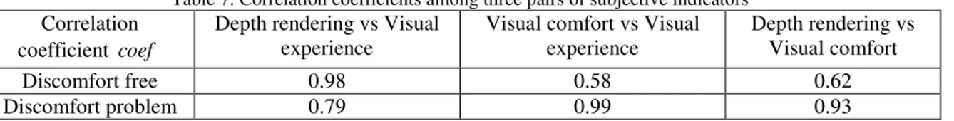
In order to understand the relationships among the subjective indicator as well as to prove the proposed priority rule (shooting rule 3), we simply regroup the subjective results into “discomfort free” (MOS value of visual comfort is equal or above 60-“good”) and “Discomfort problem” (MOS value of visual comfort is below 60-“good”) .19 stimuli and the
2 D D o F = 0 .1 D o F = 0 .2 D o F = 0 .3 D _ z = 1 0 20 40 60 80 100
Scene 1: Bunny holding the arrow and bow
2 D D o F = 0 .1 D o F = 0 .2 D o F = 0 .3 D _ z = 1 0 20 40 60 80 100
Scene 2: Bunny walking from the tree and the flower
2 D D o F = 0 .1 D o F = 0 .2 D o F = 0 .3 D _ z = 1 0 20 40 60 80 100
Scene 3: Robe skipping bunny
2 D D o F = 0 .1 D o F = 0 .2 D o F = 0 .3 D _ z = 1 0 20 40 60 80
100 Scene 4: Three standing
squirrels 2 D DoF = 0 .1 D o F = 0 .2 D o F = 0 .3 D _ z = 1 0 20 40 60 80
100 Scene 5: A tree and the
other 6 stimuli are grouped into “discomfort free” and “discomfort problem” group, respectively. Absolute Pearson product-moment correlation coefficients are calculated among three pairs of subjective indicators: Depth rendering vs Visual experience, Visual comfort vs Visual experience, Depth rendering vs Visual comfort. The result is shown in the Table 7. In discomfort free group, depth rendering has much higher relation with Visual experience (coef=0.98) compared to Visual comfort (coef=0.58). And the interaction relation between Depth rendering and Visual comfort (coef=0.62) is not strong. This confirms the proposed optimal shooting Rule 1 of optimizing the shape distortion in order to optimize the depth rendering performance. However, in discomfort problem group, Visual comfort is the dominant factor of visual experience (coef=0.99) as well as Depth rendering has high relation with Visual comfort (coef=0.93). This finding confirms the proposed priority rule – optimal shooting rule 3.
Table 7. Correlation coefficients among three pairs of subjective indicators Correlation
coefficient coef
Depth rendering vs Visual experience
Visual comfort vs Visual experience Depth rendering vs Visual comfort Discomfort free 0.98 0.58 0.62 Discomfort problem 0.79 0.99 0.93
5. CONCLUSION
In this paper, a new stereoscopic shooting rule considering both the stereoscopic distortion and comfortable viewing zone is presented. Synthetic scenes are selected in respect of different depth ranges and images are shot in different camera setting considering different conditions, e.g. DoF and shape distortion. Subjective assessment based on stereoscopic indicators is used to evaluate the perceived quality of the generated images. There are several results and findings which have indicated that the proposed shooting rules and associated priorities can ensure an optimized visual quality (depth rendering, visual comfort and visual experiences): 1) Concerning the Rule 1, the optimization of shape distortion shows its advantage in the depth rendering assessment and in the discomfort free case, the dominant effect of depth rendering on the visual experience also indicates this point. However, it is still not easy for subjects to distinguish different depth range. It may be due to the synthetic content which cause the difficulties for the subject to compare the displayed objects with the real world, further research on natural content will be needed; 2) Concerning the rule 2, comfortable viewing zone is confirmed to be around 0.2 diopter and visual comfort will drop steeply and below the “good” when out of this comfortable viewing zone. 3) The priority of Rule 2 versus Rule 1 is confirmed by the finding that in the discomfort problem case, visual comfort is the dominant factor of visual experience as well as the high relation between the depth rendering and visual comfort.
Future direction may be to generate video instead of still image as well as natural contents instead of synthetic content in order to investigate optimal shooting rules in the video domain.
REFERENCES
[1] A. J. Woods, et al., "Image distortions in stereoscopic video systems," in Stereoscopic Displays and Applications IV, San Jose, CA, USA, 1993, pp. 36-48.
[2] G. Jones, et al., "Controlling Perceived Depth in Stereoscopic Images," Proc. SPIE Stereoscopic Displays and Virtual Reality Systems VIII, vol. 4297, pp. 42-53, 2001.
[3] N. S. Holliman, "Mapping perceived depth to regions of interest in stereoscopic images," in Stereoscopic Displays and Applications XV, San Jose, CA, USA, 2004, pp. 117-128.
[4] S. Pastoor, "Human factors of 3DTV: an overview of current research at Heinrich-Hertz-Institut Berlin," in Stereoscopic Television, IEE Colloquium on, 1992, pp. 11/1-11/4.
[5] M. Wöpking, "Viewing comfort with stereoscopic pictures: An experimental study on the subjective effects of dispairty magnitude and depth of focus," Journal of the Society for Information Display, vol. 3, p. 3, 1992. [6] M. Lambooij, et al., "Stereoscopic displays and visual comfort: a review," Einhoven University of Technology
Einhoven Univeristy of Technology Philips Research, SPIE Newsroom2 April 2007.
[7] ITU, "Subjective Assessment of Stereoscope Television Pictures," in RECOMMENDATION ITU-R BT.1438, ed, 2000.
[8] S. Yano, et al., "Two factors in visual fatigue caused by stereoscopic HDTV images," Displays, vol. 25, pp. 141-150, 2004.
[9] B. Mendiburu. (2009). 3D Movie Making: Stereoscopic Digital Cinema From Scrip to Screen.
[10] H. Yamanoue, "The Differences Between Toed-in Camera Configurations and Parallel Camera Configurations in Shooting Stereoscopic Images," in Multimedia and Expo, 2006 IEEE International Conference on, 2006, pp. 1701-1704.
[11] H. Yamanoue, et al., "Geometrical analysis of puppet-theater and cardboard effects in stereoscopic HDTV images," Circuits and Systems for Video Technology, IEEE Transactions on, vol. 16, pp. 744-752, 2006. [12] W. Chen, et al., "New requirements of subjective video quality assessment methodlogies for 3DTV," in Fifth
International Workshop on Video Processing and Quality Metrics for Consumer Electronics - VPQM 2010, Scottsdale, Arizona, U.S.A., 2010.
[13] D. B. Diner, "A new definition of orthostereopsis for 3D television," in EEE International Conference on Systems, Man, and CyberneticsI, 1991, pp. 1053-1058 vol.2.
[14] B. foundation. (2008, Big buck bunny. Available: http://www.bigbuckbunny.org/ [15] B. foundation. Blender. Available: www.blender.org
[16] J. E.Cutting and P. M.Vishton, "Perceiving layout and knowing distances: The integration, relative potency, and contextual use of different information about detph," in Handbook of perception and cognition. vol. 5, E. W. and R. S., Eds., ed San Diego: Academic Press, 1995.
[17] L. Goldmann, et al., "A comprehensive database and subjective evaluation methodology for quality of experience in stereoscopic video," in Three-dimensional Image Processing and Application, San Jose, California, USA, 2010, pp. 75260S-11.
[18] L. Goldmann, et al., "Impact of acquisition distortions on the quality of stereoscopic images," in Fifth International Workshop on Video Processing and Quality Metrics for Consumer Electronics - VPQM 2010, Scottsdale, Arizona, U.S.A., 2010.
[19] ITU, "Methodology for the subjective assessment of the quality of television pictures," in Recommendation BT 500-11, ed: International Telecommunication Union., 2002.
[20] J. L. Blin, "New quality evaluation method suited to multimedia context SAMVIQ," in The Second International Workshop on Video Processing and Quality Metrics for Consumer Electronic, Phoenix,Arizona, 2006.