HAL Id: hal-02169279
https://hal.archives-ouvertes.fr/hal-02169279
Submitted on 11 May 2020
HAL is a multi-disciplinary open access
archive for the deposit and dissemination of
sci-entific research documents, whether they are
pub-lished or not. The documents may come from
teaching and research institutions in France or
abroad, or from public or private research centers.
L’archive ouverte pluridisciplinaire HAL, est
destinée au dépôt et à la diffusion de documents
scientifiques de niveau recherche, publiés ou non,
émanant des établissements d’enseignement et de
recherche français ou étrangers, des laboratoires
publics ou privés.
Simplified Analysis of the Early Stage Self-loosening of a
Shear-Loaded Bolted Joint
Vincent Rafik, Alain Daidié, Bertrand Combes, Clément Chirol
To cite this version:
Vincent Rafik, Alain Daidié, Bertrand Combes, Clément Chirol. Simplified Analysis of the Early
Stage Self-loosening of a Shear-Loaded Bolted Joint. Springer. ICTAEM 2019: Proceedings of the
Second International Conference on Theoretical, Applied and Experimental Mechanics, 8, Springer,
pp.169-175, 2019, 978-3-030-21894-2. �10.1007/978-3-030-21894-2_33�. �hal-02169279�
Simplified Analysis of the Early Stage Self-loosening of a
Shear-loaded Bolted Joint
Vincent Rafik
1,2, Alain Daidié
1, Bertrand Combes
1and Clément Chirol
2 1 Université de Toulouse, Institut Clément Ader, UMR CNRS 5312, INSA/UPS/ISAE/Mines Albi, 3 rue Caroline Aigle, 31400 Toulouse, France 2 AIRBUS France, Materials & Processes, Assembly Technology, Rue Marius Tercé,31200, Toulouse, France vincent.rafik@insa-toulouse.fr
Abstract. The self-loosening of a joint through unscrewing of the bolt is a phenomenon mainly occurring when
the assembly is solicited by transverse repeated loads. Previous works highlighted that the transversal sliding of the bearing surfaces, either in the threads or underneath the bearing surfaces of bolts and/or nuts, is its root cause and that this phenomenon begins during the first loading cycles. In order to study the early stage of this self-loosening, a simplified numerical model has been developed. The latter factors the bearing surfaces of the bolt, the preload, the friction coefficient, the amplitude of the shear-load and the fastener’s material. Through measurements and interpretation of the results, the shearing of the fastener has been identified as the main deformation leading to the self-loosening of the assembly, while the bending of the fastener shank limits the self-loosening. Moreover, according to the values of preload and shear-load, the behaviors were identified, and an interpretation has been proposed.
Keywords: self-loosening, bolted joints, shear-load, finite elements analysis.
I.
Introduction
A. The self-loosening in the literature
A few scientists such as Reid, Hattori or Dinger [1, 2, 3] highlighted that in some specific conditions, the self-loosening of the fasteners clamping the pieces of a structure together can be noticed. This phenomenon might be due to an excessive cycled shear-loading of the parts. In order to focus on this phenomena, several papers are studying the self-loosening of a single bolted joint to get rid of the additional phenomena implied by the bolting sequence in a multi bolted assembly [4, 5, 6, 7].
Junker [4] is the first to have studied this phenomenon. Thanks to a specific test bench, he considered the sliding of the bearing surfaces of the fasteners and the bolt’s bending as its root cause. Dinger and Zhou [3, 5] studied the influence of the bolt coating on the self-loosening of the joint. They noticed that the lower was the friction coefficient, the most severe was its self-loosening as it can be seen on the Fig. 1. Whichever the coating Zhou considered; the loss of normal strength could be observed. Indeed, the higher was the friction coefficient, the latter and the slower was the phenomena.
Figure 1: Loosening curve for different fastener coatings [5]
2
or under the head. According to Jiang [7], the loosening curves can be split into two parts, Fig. 2. Moreover, he stated that the early loosening “Stage I”, is driving the phenomena as the first movement or deformation, breaking the bolt’s steadiness, were the most important one.
Figure 2. The self-loosening sequence, [7]
B. Purpose of the study
Understanding which process implies the early self-loosening might help us to avoid the loss of preload due to the rotation of the fastener. To do so, a simplified numerical model of the contact between the fastener’s bearing surfaces and the clamped part will be developed. Once this model has been validated thanks to specific tests, an analysis will be done in order to identify the process and more specifically the deformation, either shearing or bending, leading to the self-loosening of the assembly. Finally, an analytical approach will aim at proposing a definition of the loosening load, the effort implying the loss of preload.
II.
The numerical analysis
A. Presentation of the modelWe will study an assembly of three plates (Fig. 3.a) tightened together by a bolt, solicited transversally by a sinusoidal shaped load. Our model, developed on Abaqus (Fig. 3.b), only represents the head of the fastener, a part of its shank and its bearing plates. The bolt (diameter 9.52 mm, in red), is in titanium whereas the plate (with bore clearance of 30µm, in light grey) is in aluminum. The simulation is composed of 3 steps. The first one is an axial loading F0 to apply a preload on section Sb. A maximum preload of 28 000 N, chosen according to Airbus standards, corresponds to 60% of the yield strength for the Ti4Al6V. The second one is an axial torque C0 applied to the section Sb, to consider the reaction of the nut’s threads on the bolt’s threads due to the preload. The last one is the shear-loading of the assembly by a sinusoidal shear-load Ft(t) at a frequency of 5 Hz, applied to the cylinder Ct.
Two contacts with Coulomb friction are modeled (Fig. 3b):
• Contact ①: Between the aluminum coated bolt’s head and the primer coated bearing surface of the plate, f = 0.06.
a b
Figure 3. Definition of the complete assembly (a) and the model (b)
The variation of three parameters will be tested. Their values are presented Table 1. The influence of the preload and shear-load will aim at identifying the process leading to the self-loosening whereas the Young modulus of the bolt will highlight which deformation implies the phenomena.
Table 1. Definition of the parameters
Parameters Shear-load (N) Preload (N) Young modulus (GPa)
Number of values 50 5 10
Range of values 30 - 25 000 500 - 25 000 60 - 250
B. The results
1. Influence of the shear-load
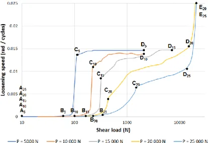
In a first step, the influence of the amplitude of the shear-load has been investigated. For each preload value, the loosening speed (i.e. the mean rotation of the bolt for one loading cycle, measured in steady state after a stabilization time) has been plotted vs the amplitude of the shear-load, Fig. 4.
4 The curves can be split into several parts from A to E:
• Part AB: The head of the fastener sticks to its bearing surface. Therefore, the bolt cannot rotate.
• Part BC: Beyond a certain shear-load, the head starts to slip on the plate. The loosening of the fastener can be noticed. Up to a preload of 15 000 N, this part is vertical, which correspond to the Coulomb theory. The corresponding loading will be qualified as “loosening load”. As soon as the solicitation reaches it, the distance of the head’s slipping will be the clearance as the bending is negligible. For higher preload, the shear-load necessary for the head to slip will imply the fastener bending. Then, the slipping distance will be lower as well as the loosening speed.
• Part CD: For low preload, once the fastener slides, its shank will contact the plate hole. The sliding will be stopped and the loosening speed will be the same whatever the shear-load in the part CD. For higher preload, the fastener will bend more, the slipping distance and the loosening speed will be lower. But when the shear-load increases, the contact between the shank and its hole gets closer to the head. So the slipping distance and the loosening speed increases with the shear-load.
• Part DE: The shear-load is sufficiently high to cause the plastic deformation of the hole, causing its ovalization, then the possible sliding distance becomes larger and the loosening angle caused by the head slipping is higher.
2. Influence of the preload
Then, the influence of the normal stress has been investigated. In order to do so, the preload and the torque applied during the first and second simulation steps has been changed a simulation from another. For each of them, the evolution of the loosening load, defined by points B on Fig. 4, has been plotted on the Fig. 5.
Figure 5. Loosening load vs the preload.
The loosening load is proportional to the preload, which matches the Coulomb theory. This result shows that for this level of shear-load and for any preload considered, the plate’s deformation is negligible as the fastener will slide on the plate for a specific load which could be calculated thanks to an analytical model with simple hypothesis.
3. Influence of the Young modulus
Bending and shearing of the shank are caused by the shear-loading of the fastener. In order to define which one implies the loss of preload, the influence of the fastener material has been investigated. The loosening speed for preload of 28 000 N and shear-load of 10 000 N for different Young modulus of the bolt has been plotted Figure 6.
Figure 6. Influence of the Young Modulus on the loosening speed.
We observe that the higher the fastener’s Young modulus is, the lower its bending deformation is, and the more severe its self-loosening. So we can conclude that the bending of the bolt prevents the self-loosening. This can be attributed to the contact of the bolt shank and its hole, that happens earlier when the shank bends, and which decreases the amplitude of the sliding of the head on the plate as seen before.
III.
Conclusion
The self-loosening is a phenomenon characterized by a loss of preload within the joint coming from unscrewing. Its root cause is the sliding of the bolt’s bearing surface caused by an excessive shear-load. It has been proven that the early stage of the phenomena is driving the subsequent rotation. In order to study the behavior of the bolt during the first cycles, a simplified numerical model including only a part of the bolt and a plate has been developed. Thanks to it, the influences of the preload, the amplitude of shear-load and the fastener material have been investigated.
The results highlighted that whichever the preload and beyond a certain shear-load, the bolt will self-loosen, matching the Coulomb theory. However, for high value of preload, this simple theory is not sufficient as the bending of the bolt shank induces a contact of the shank on its hole, which reduces the sliding of the bolt head and the unscrewing. Finally, the shearing of the bolt has been identified as the main solicitation implying the self-loosening. Indeed, the higher is the bolt’s bending rigidity, the more severe is its self-self-loosening.
References
1. Reid, J D.: Detailed modeling of bolted joints with slippage. Finite Elements in Analysis and Design 41, 547–562 (2005). 2. Hattori, T.: Loosening and Sliding Behaviour of Bolt-Nut Fastener under Transverse Loading. In: 14th International
Conference on Experimental Mechanics, 08002-p.1–08002-p.8. EPJ Web of Conferences (2010).
3. Dinger, G.: Design of multi-bolted joints to prevent self-loosening failure. Journal of Mechanical Engineering Science 230(15), 2564–2578 (2016).
4. Junker, G. H.: New Criteria for Self-Loosening of Fasteners Under Vibration. Soc. Automot Eng 78, 314–335(1969). 5. Zhou, J.: Anti-loosening performance of coatings on fasteners subjected to dynamic shear load. Friction 6, 32–46 (2018). 6. Zadoks, R. I.: An investigation of the self-loosening behavior of bolts under transverse vibration. Journal of Sound and
Vibration 208 (2), 189–209 (1997).
![Figure 1: Loosening curve for different fastener coatings [5]](https://thumb-eu.123doks.com/thumbv2/123doknet/11395986.287487/2.892.349.565.872.1036/figure-loosening-curve-different-fastener-coatings.webp)
![Figure 2. The self-loosening sequence, [7]](https://thumb-eu.123doks.com/thumbv2/123doknet/11395986.287487/3.892.309.600.258.418/figure-the-self-loosening-sequence.webp)