HAL Id: hal-02144433
https://hal.archives-ouvertes.fr/hal-02144433
Submitted on 30 May 2019HAL is a multi-disciplinary open access
archive for the deposit and dissemination of sci-entific research documents, whether they are pub-lished or not. The documents may come from teaching and research institutions in France or abroad, or from public or private research centers.
L’archive ouverte pluridisciplinaire HAL, est destinée au dépôt et à la diffusion de documents scientifiques de niveau recherche, publiés ou non, émanant des établissements d’enseignement et de recherche français ou étrangers, des laboratoires publics ou privés.
in carbon/epoxy laminates
Ophélie Westphal, Laurent Gornet, Laurent Stainier, Patrick Rozycki
To cite this version:
Ophélie Westphal, Laurent Gornet, Laurent Stainier, Patrick Rozycki. Thermomechanical analysis of fatigue induced damages in carbon/epoxy laminates. 15th European Conference on Composite Materials (ECCM15), Jun 2012, Venise, Italy. �hal-02144433�
THERMOMECHANICAL ANALYSIS OF FATIGUE INDUCED
DAMAGES IN CARBON/EPOXY LAMINATES
O.Westphal1*, L.Gornet1, L.Stainier1, P.Rozycki1 1
Laboratoire de Génie Civil et Mécanique, Equipe Structures et Simulations, Ecole Centrale de Nantes, 1 rue de la Noë 44200 Nantes, France
Keywords: fatigue, self-heating, damage, thermomechanical behavior
Abstract
The tensile fatigue behavior of a high stress carbon fiber epoxy-matrix composite laminates was examined at room temperature. Tension-tension cyclic fatigue tests were also conducted under load control at a sinusoidal frequency of 5 Hz to obtain stress-fracture cycles (S-N) relationship. The fatigue limits of the different lay-up tested were found and compared with the data resulting from self-heating tests on the same materials. This comparison reveals a good accordance between the two methods of fatigue limit determination. A macroscopic fatigue damage evolution law is then proposed to reproduce the experimental data.
1. Introduction: Rapid determination of fatigue limit with self-heating tests
Rapid estimation method of fatigue limits has already been recently derived by authors for several materials [1-5]. The thermal effects associated with cyclic loading are the key point of the so-called “heating tests” method. Results of this method show good accordance with those revealed by classical fatigue tests (Wöhler curves) for some metallic materials and rubber materials [3-4]. This “heating tests method” consists in applying successive sets of a given number of cycles for increasing stress levels. For each stress level, the temperature variation is recorded and the steady-state temperature is determined. Beyond a given limit, it is observed that steady state temperature starts to increase significantly [3]. This change is correlated with the state where the fatigue limit is exceeded and can be related to the apparition of dissipation phenomena which occurs in the material and govern the fatigue properties [5-7].
In this work, the heating test method is applied in order to determine the fatigue property of a unidirectional high-stress carbon-fiber epoxy-matrix material. A correlation between the mean fatigue limit for composite laminates and the heat build-up is presented. Moreover, a damage model derived at the micro scale has been proposed to create the heat build-up of the mechanical tests. Indeed, by using this model, it is possible to predict the Wöhler curve of the laminate. A canonical base of four mechanical tests associated to finite elements simulations is proposed to determine all the fatigue three-dimensional mechanical properties of the elementary ply.
Fatigue damage evolution laws are commonly developed nowadays [8] for composite laminates; prediction models are proposed for layers [9] and delamination [10]. In this work, we base on a simple macroscopic damage evolution law for laminates.
2. Material and experimental procedures 2.1 Material
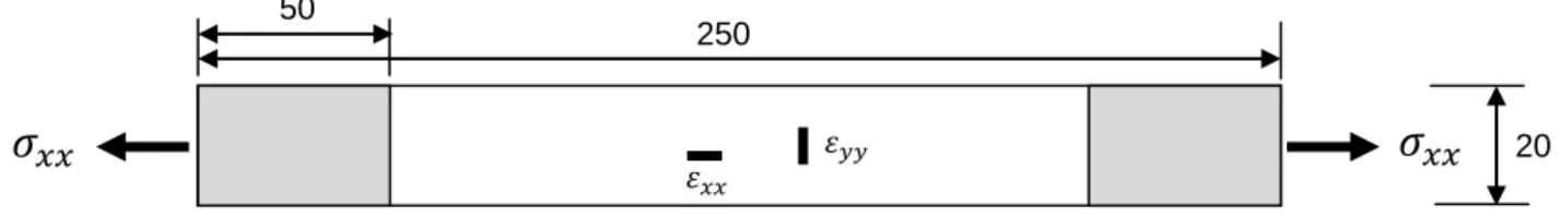
Quasi-static, fatigue and self-heating tests have been conducted on symmetrical carbon-fiber epoxy-matrix laminated specimens (ASTM D3039, ISO 527) of dimensions 250*20 millimeters. Four stacking sequences have been tested: [±67,5]s, [±45]s, [0/90/0/90]s, [-45/45/90/0]s. The off-axis tests give rise to combine shear and in-plane properties. The tests on quasi-isotropic laminates are used with the aim of validating the future model. These laminates are combinations of three basic arrangements: unidirectional, angle-ply and cross-ply laminates. The number of plies is always 8 for all tested laminates.
All the lay-up were manufactured by the oven forming technique. The prepregs were laid up by hand in a mold and then put into a vacuum bag for curing at 120°C.
Some specimens have been equipped with biaxial gages of 3 millimeters grid length (HBM XY91-3/350). Gages were placed at the specimen centre.
Figure 1. Geometry and dimensions of the specimens.
2.2 Testing procedures
All the tests were carried out on MTS 880-100kN servo-hydraulic machine at room temperature (RT, ~20°C).
For quasi-static tension tests, a displacement rate of 2mm/min has been chosen. These tests have been conducted until specimen fracture to yield the basic mechanical properties of the elementary ply. Temperature changes have been measured with a CEDIP infrared camera. To evaluate the temperature evolution on the specimen surface due to internal degradation phenomena, the temperature of a reference specimen was subtracted from that of tested specimen. The reference specimen was of same stratification. This method allows us to remove temperature fluctuations due to environmental conditions.
Fatigue tests were performed under tension-tension (T-T) cyclic loadings of constant stress amplitude. The loading frequency was 5 Hz. Fatigue tests were stopped if one of the following conditions occurred: the specimen broke out or the specimen was unbroken after 3 million cycles. Stress unloading stages have been planned during all fatigue tests to measure the stiffness decrease of specimens.
The self-heating tests were performed under tension-tension cyclic loading with constant mean stress. Each loading block is made up of a first loading stage until reaching the mean stress, a cyclic loading stage of 3000 cycles at constant stress amplitude and a return stage to
250 50 20
zero stress. The first and third stages were displacement-controlled and the second stage was force-controlled. Each loading block contains 3000 cycles (number of cycles needed for stabilizing the temperature). After each loading condition, the stress has been entirely relaxed for 5 minutes to yield the thermal equilibrium again. The temperature on the specimen surface was measured with an infrared camera.
2.3 Temperature measurement
In order to determine the temperature field on the surface of the specimen, a nonintrusive measurement technique by infrared thermography was chosen. In the test, an infrared camera from Cedip Infrared Systems (made up of a matrix of 320*240 Mercury Cadmium Telluride detectors) was used to record the temperature changes during the quasi-static and self-heating tests. The precision of the camera is 1mK. The experimental device leads to a spatial resolution of 0.7mm. Surfaces of the specimen tested were black because of the carbon fibre colors, so no black paint has been deposited on the specimen surface; the surface emissivity has been determined experimentally by comparing results of thermocouples and camera data. A preliminary calibration operation allows the conversion of the thermosignal (proportional to the thermal radiation) into a temperature in degree Celsius (°C). The acquisition rate was 25 frames per second. The use of an infrared camera gives us access to a surface measurement (2D). However, the specimens are thin enough to avoid a too high core/skin temperature ratio.
3 Experimental results and discussion 3.1 Static loading test
In this part, main results from quasi-static tests on [±67,5]s, [±45]s, [0/90/0/90]s and [±45/90/0]s laminates are presented. These tests allow especially to detect thermomechanical couplings in the laminate studied and to determine more precisely mechanical characteristics of the material (notably the limit of elasticity) [6].
Figure 2. Results of tensile tests on [±67,5]s
carbon/epoxy laminate
Figure 3. Results of tensile tests on [±45]s
carbon/epoxy laminate -0,35 -0,3 -0,25 -0,2 -0,15 -0,1 -0,05 0 0,05 0 10 20 30 40 50 60 70 0 0,5 1 M e a n temp e ratu re θ (° C) A x ia l st re ss σxx ( MP a ) Axial strain εxx -0,25 0 0,25 0,5 0,75 1 1,25 1,5 1,75 2 0 20 40 60 80 100 120 140 160 0 5 10 15 M ean t emperat ure θ (° C) A x ia l st re ss σxx ( MP a ) Axial strain εxx
Figure 4. Zoom on results of tensile tests on [±67,5]s
carbon/epoxy laminate between and
Figure 5. Zoom on results of tensile tests on [±45]s
carbon/epoxy laminate between and
Figure 6. Results of tensile tests on [0/90/0/90]s
carbon/epoxy laminate
Figure 7. Results of tensile tests on quasi-isotropic
carbon/epoxy laminate (stratification [±45/90/0]s)
In Figure 2, stress and temperature are presented versus strain for a [±67,5]s laminate. The stress-strain curve didn’t show any sign of irreversible strain. The temperature-strain curve exhibits a short increase then is linear and decrease until final fracture. This second evolution may be explained by the linearly elastic behavior of the lay-up. Thermoelastic effects are predominant.
In Figure 3, stress and temperature are presented versus strain for a [±45]s laminate. The curve exhibits three areas. In the first area, the temperature decreases linearly with increased stress until the elastic limit was reached. After the elastic limit, the temperature starts to increase. In this area, the material has a non-linear elastic behavior. During the irreversible strain stage of the off-axis laminate, the temperature keeps on increasing, but the temperature increasing rate is not the same as in the second area. Besides, a knee in the curve is well visible. The laminate macrofissurations and finally the laminate failure release an important heat quantity, which increase suddenly the temperature on the specimen surface.
In Figure 6, axial stress and temperature are presented versus axial strain for a cross-ply [0/90/0/90]s laminate. The stress-strain relationship for the cross-ply laminate is almost linear up to failure. The temperature first decreases with increased stress, stabilizes and then increases until composite failure. This temperature increase and stabilization may represent the thermal phenomenon of the transverse plies until their total failure. Once the transverse plies are entirely broken, only the thermal characteristics of the longitudinal plies govern the
-0,2 -0,15 -0,1 -0,05 0 0,05 0 10 20 30 40 50 60 70 0 0,2 0,4 M ean t emperat ure θ (° C) A x ia l st re ss σxx ( MP a ) Axial strain εxx -0,2 -0,15 -0,1 -0,05 0 0,05 0 20 40 60 80 100 120 140 160 0 0,2 0,4 M ean t emperat ure θ (° C) A x ia l st re ss σxx ( MP a ) Axial strain εxx -0,3 -0,25 -0,2 -0,15 -0,1 -0,05 0 0,05 0,1 0,15 0,2 0 200 400 600 800 1000 1200 0 0,005 0,01 0,015 0,02 M ean t emperat ure θ (° C) A x ia l st re ss σxx ( MP a ) Axial strain εxx -0,4 -0,35 -0,3 -0,25 -0,2 -0,15 -0,1 -0,05 0 0,05 0 100 200 300 400 500 600 700 0 0,005 0,01 0,015 0,02 M ea n t emp er atu re θ (° C) A x ia l st re ss σxx ( MP a ) Axial strain εxx
temperature evolution in the composite. The temperature increases slightly with stress. The heating of the fibres (due to their negative coefficient of thermal expansion in the longitudinal direction) dominates over the cooling down of the matrix.
In Figure 7, stress and temperature are presented versus strain for a quasi-isotropic [-45/+45/90/0]s laminate. The stress-strain relationship for this laminate is almost linear with a light knee around 400 MPa, which can be assimilated to the fracture of 45° plies. The mean temperature changes in similar ways as in the cross-ply [0/90/0/90]s laminate. The temperature strain curve first decreases then increases until final fracture of the composite. The temperature increase begins with the entire fracture of transverse plies and damage increase in 45° plies. After fracture of 45° plies, the temperature keeps on raising until failure of unidirectional plies.
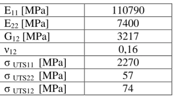
Table 1 lists the tensile mechanical properties of the laminate at ambient temperature.
E11 [MPa] 110790 E22 [MPa] 7400 G12 [MPa] 3217 ν12 0,16 σ UTS11 [MPa] 2270 σ UTS22 [MPa] 57 σ UTS12 [MPa] 74
Table 1. Mechanical properties of the carbon fiber-epoxy matrix elementary ply
3.2 Static loading-unloading test for [±45/90/0]s laminate
To evaluate the link between damage evolution and temperature changes (dissipative behavior), static loading-unloading tests were conducted. The loading-unloading cycles were repeated ten times, changing the maximum stresses. The envelope stress-strain curve is similar to the one depicted in Figure 7. Figure 8 shows the stress-strain curves for a quasi-isotropic laminate and corresponding temperature changes during three loading-unloading cycles (a), (b) and (c). The temperature scales are the same to make comparisons of thermal phenomena easier.
(a)
(b)
(c)
Figure 8. Stress-strain curves for quasi-isotropic carbon/epoxy laminate (stratification [±45/90/0]s) and
temperature changes during quasi-static loading-unloading test
: mechanical behavior, :thermal response
-0,2 -0,1 0 0,1 0,2 0,3 0 20 40 60 80 100 120 0 0,0005 0,001 0,0015 0,002 0,0025 T e m pe ra tur e cha nge Δθ (° C) A x ia l st re ss σxx (MP a ) Axial strain εxx Loading Unloading -0,2 -0,1 0 0,1 0,2 0,3 0 50 100 150 200 250 300 350 400 0,000 0,002 0,004 0,006 0,008 T e m pe ra tur e cha nge Δθ (° C) A x ia l st re ss σxx (MP a ) Axial strain εxx Loading Unloading -0,2 -0,1 0 0,1 0,2 0,3 0 100 200 300 400 500 600 0 0,005 0,01 0,015 0,02 0,025 T em pera ture cha ng e Δθ (° C) A x ia l st re ss σxx (MP a ) Axial strain εxx Unloading Loading
During the first cycle (up to 100 MPa), the laminate behavior is linear elastic (Figure 8a). The residual inelastic strain remains equal to zero. The temperature decreases while stress is increasing then increases while the stress is relaxing. This thermal behavior results from the thermoelastic effect.
During the second cycle (up to 350 MPa), the laminate damages lead to a residual inelastic strain equal to 0,94.10-4 (Figure 8b). The temperature decreases in linear elastic step of material behavior then increases with the material damage. The unloading stage corresponds to a linear stress return and a linear temperature increase. During this second cycle, microstructural damage evolution leads to local irreversible strain and thus to mechanical energy partially dissipated into heat. Another part of mechanical energy is dissipated by conduction inside the tested specimen.
During the third cycle (up to 550 MPa), the laminate damages lead to a residual irreversible strain equal to 1,0.10-3 (Figure 8c). The mechanical and thermal phenomena always observed for the second cycle are amplified at this strain level. The stress-irreversible strain curve for the test is presented Figure 9.
Figure 9. Stress versus irreversible strain curve for quasi-isotropic carbon/epoxy laminate (stratification [±45/90/0]s)
3.3 S-N fatigue relation-ships and comparison with results from self-heating tests
Figure 10 presents the temperature measurements obtained for [0/90/0/90]s laminate and a proposal of empirical analysis, similar to the one proposed for metallic materials [1-3], for the mean stress 500 MPa.
Figure 12 presents the self-heating curves obtained for the [±45]s laminates and a proposal of empirical analysis for the mean stress of 50 MPa. The temperature rising is more marked than for the [0/90/0/90]s laminates.
The experimental data of the axial stress versus number of cycle of laminates [±45]s and [0/90/0/90]s for the tension-tension fatigue tests are shown in Figure 11 and Figure 13 respectively, where is the number of fatigue stress cycles up to failure and is the maximum stress applied. In these figures, dashed lines correspond to results obtained by the empirical analysis of self-heating tests.
0 100 200 300 400 500 600 0 0,0005 0,001 0,0015 0,002 0,0025 σxx εirr xx
The comparison between results from Wöhler curves and from self-heating tests shows the empirical analysis of self-heating gives good results for our composites also. Further tests are in progress, notably on quasi-isotropic laminates.
Figure 10. Self-heating curve for the [0/90/0/90]s
laminate: steady-state temperature versus maximum stress.
Δ: = 500 MPa
Figure 11. Wöhler diagram for the same laminate
[0/90/0/90]s for tension/tension tests at = 500
MPa. The open symbols are experimental data and the dashed line is the fatigue limit revealed by the
self-heating test.
Figure 12. Self-heating curve for the [±45]s laminate:
steady-state temperature versus maximum stress.
◊: = 50 MPa
Figure 13. Wöhler diagram for the same laminate
[±45]s for tension/tension tests at = 50 MPa. The
open symbols are experimental data (blank cercle: no failure) and the dashed line is the fatigue limit
revealed by the self-heating test.
4 Numerical modeling
A finite-element model is build using the Finite Element code Cast3M. The UD ply is assumed to be composed of two phases: carbon fibers and surrounding ductile epoxy matrix. The fibers are supposed to be not subjected to fatigue damage. Only the matrix is supposed to have a fatigue dependent behavior. The tridimensional elastic behavior of the composite layer is obtained by periodic homogenization.
0 0,5 1 1,5 2 2,5 0 500 1000 S tead y -stat e tem pera ture (° C)
Maximal stress σmax (MPa)
0 200 400 600 800 1000 1200 1 100 10000 1000000 Ma x im a l st re ss σma x (MP a )
Number of cycle to failure Nr
0 1 2 3 4 5 6 0 50 100 S tead y -stat e temperat ure (° C)
Maximal stress σmax (MPa)
0 50 100 150 1 100 10000 1000000 Ma x im a l st re ss σma x (MP a )
A cumulative damage is used to predict the macroscopic degradation evolution of the
homogeneous laminate’s modulus during the fatigue tests. The damaged behavior law of the
laminate is presented: (1)
With respect to the experimental data, the following damage evolution law is proposed:
(2)
where is the number of cycles, is the damage variable for N cycles, the strain amplitude applied during the cyclic loading, a parameter associated with the fatigue limit,
a parameter associated with the slope of the fatigue curve, a parameter associated with the
life time and a parameter associated with the concavity of the curve.
We assume that the parameters are constant. Integration of (1) over cycle leads to equation (3): for (3) with (4)
where represents the number of cycles up to fracture and the critical value of at the failure of the laminate sample. Fitted values of the damage law chosen are shown for the four stacking sequences tested in Table 2. The relative estimation error on law parameters is calculated according to the least square method between model and experimental curve.
[±67,5]s laminate [±45]s laminate [0/90/0/90]s laminate [±45/90/0]s laminate κ 0,00030456 0,72335844 0,90006371 0,9 α -6,06549829 -100 -1467,98526 -359,516358 β 25,6177372 24,5953878 55,4249546 26,1498111
Relative
error 0,0003154 0,00038062 0,00022442 0,00092577
Table 2. Fitted values of damage law (1) for the [±67,5]s laminate, [±45]s laminate, [0/90/0/90]s laminate and for
the [±45/90/0]s laminate
5 Conclusion
This paper deals with the fast determination of fatigue limit of carbon/epoxy laminated composites under cyclic loadings by self-heating measurements.
Preliminary studies were conducted on thermomechanical behavior under quasi-static tensile loadings of this material. Temperature measurements were made on [±45]s, [0/90/0/90]s cross-ply and [±45/90/0]s quasi-isotropic laminates during classical tensile tests and loading-unloading tests. The behavior appears to correspond well to what is known about temperature changes in other materials. In elastic loading, the temperature decreases linearly with the applied stress. When cracks appear, the temperature immediately starts to increase significantly. In the quasi-isotropic laminate, temperature changes seem to be the sum of thermal events in each ply. Thermal response of the longitudinal plies comes after the full degradation and fracture of the transverse then [±45]s plies.
Fatigue behavior for tension-tension loading conditions was studied for carbon/epoxy laminated composites. The fatigue limit resulting from self-heating tests and estimated limit based on classical Wöhler curves were found to be in good agreement for the carbon/epoxy laminates of [±45]s and [0/90/0/90]s stacking sequences. New experiments are currently in progress to compare the both methods at other stress levels and for other stratification like quasi-isotropic stratifications.
For modeling the fatigue response of the laminate, a macroscopic cumulative damage law is proposed. The final goal is to introduce this fitted law in a non-isothermal damageable non linear model, developed within the framework of continuum damage mechanics, in order to simulate the temperature rise observed during self-heating tests at the ply and interface level.
6 References
[1] La Rosa G., Risitano A., Thermographic methodology for rapid determination of the fatigue limit of materials and mechanical components, International Journal of Fatigue,
22, pp. 65–73 (2000).
[2] Clienti C., Fargione G., La Rosa G., Risitano A., Risitano G., A first approach to the analysis of fatigue parameters by thermal variations in static tests on plastics,
Engineering Fracture Mechanics, 77, pp. 2158-2167 (2010).
[3] Ezanno A., Doudard C, Calloch S., Millot T., Heuzé J.-L., Fast characterization, of high-cycle fatigue properties of a cast copper-aluminium alloy by self-heating measurements under cycle loadings, Procedia Engineering, 2, pp.967-976 (2010).
[4] Le Saux V, Marco Y., Calloch S., Doudard C., Charrier P., Fast evaluation of the fatigue lifetime of rubber-like materials based on a heat build-up protocol and micro-tomography measurements, International Journal of Fatigue, 32, pp. 1582-1590 (2010).
[5] Chrysochoos A., Louche H., An infrared image processing to analyze the calorific effects accompanying strain localization, International Journal of Engineering Science, 38, pp.1759-1788 (2000).
[6] Breglund L.A., Lindhagen J.E., Temperature changes in polymer composites during tensile loading, Journal of Material Science, 32, pp.4071-4076 (1997).
[7] Costa-Mattos H., Calas Lopes Pacheco PM, Non-isothermal low-cycle fatigue analysis of elasto-viscoplastic materials, Mechanics Research Communications, 36, pp. 428-436 (2009).
[8] Bodin D., Pijaudier-Cabot, La Roche C., Piau J-M., A continuum Damage Approach to Asphalt Concrete Fatigue Modeling, Journal of Engineering Mechanics, ASCE, 130, pp. 700-708 (2004).
[9] Hochard Ch. Thollon Y., A generalized damage model for woven ply laminates under static and fatigue loading conditions, International Journal of Fatigue, 32, pp. 158-165 (2010).
[10] Gornet L., Ijaz H., High Cycle Fatigue Damage Model for Delamination Crack Growth in CF/Epoxy Composite Laminates, International Journal of Damage Mechanics, 20, pp. 783-807 (2011).
[11] Quaresimin M., Susmel L., Talreja R., Fatigue behaviour and life assessment of composite laminates under multiaxial loadings, International Journal of Fatigue, 32, pp.2-16 (2010).
[12] Kawai M., Sagawa T., Temperature dependence of off-axis tensile creep rupture behavior of a unidirectional carbon/epoxy laminate, Composites Part 1: Applied Science and
![Figure 2. Results of tensile tests on [±67,5] s carbon/epoxy laminate](https://thumb-eu.123doks.com/thumbv2/123doknet/11325189.283027/4.892.134.802.697.906/figure-results-tensile-tests-s-carbon-epoxy-laminate.webp)
![Figure 4. Zoom on results of tensile tests on [±67,5] s carbon/epoxy laminate between and](https://thumb-eu.123doks.com/thumbv2/123doknet/11325189.283027/5.892.175.787.107.319/figure-zoom-results-tensile-tests-carbon-epoxy-laminate.webp)
![Figure 8. Stress-strain curves for quasi-isotropic carbon/epoxy laminate (stratification [±45/90/0] s ) and temperature changes during quasi-static loading-unloading test](https://thumb-eu.123doks.com/thumbv2/123doknet/11325189.283027/7.892.252.640.109.1060/figure-stress-isotropic-laminate-stratification-temperature-changes-unloading.webp)
![Figure 9. Stress versus irreversible strain curve for quasi- quasi-isotropic carbon/epoxy laminate (stratification [±45/90/0]s)](https://thumb-eu.123doks.com/thumbv2/123doknet/11325189.283027/8.892.280.616.519.727/figure-stress-versus-irreversible-strain-isotropic-laminate-stratification.webp)
![Figure 11. Wöhler diagram for the same laminate [0/90/0/90] s for tension/tension tests at = 500 MPa](https://thumb-eu.123doks.com/thumbv2/123doknet/11325189.283027/9.892.110.436.217.439/figure-wöhler-diagram-laminate-tension-tension-tests-mpa.webp)
