This is an author-deposited version published in: https://sam.ensam.eu
Handle ID: .http://hdl.handle.net/10985/10078
To cite this version :
Paola CINNELLA, Bruno MICHEL - Toward improved simulation tools for compressible
turbomachinery: assessment of Residual-Based Compact schemes for the transonic compressor NASA Rotor 37 - International Journal of Computational Fluid Dynamics - Vol. 28, p.31-40 - 2014
To appear in the International Journal of Computational Fluid Dynamics Vol. 00, No. 00, 00 Month 201X, 1–9
ARTICLE
Toward improved simulation tools for compressible turbomachinery:
assessment of Residual-Based Compact schemes for the transonic
compressor NASA Rotor 37
P. Cinnellaa∗ and B. Michelb
aLaboratoire DynFluid, Arts et M´etiers ParisTech, 151 Bd de l’Hˆopital, 75013 Paris, France; bD´epartement DSNA, Onera, 92320, Chˆatillon, France
(???)
Residual-based-compact schemes (RBC) of 2nd and 3rd-order accuracy are applied to a challenging 3D flow through a transonic compressor. The proposed schemes provide almost mesh-converged solutions in good agreement with experimental data on relatively coarse grids, which allows achieving a given accuracy level with computational cost reductions by a factor between 2 and 4 with respect to standard solvers.
Keywords: Transonic compressor, Residual-Based compact scheme, high order
1. Introduction
The high complexity of turbomachinery flows, which are three-dimensional, unsteady, and often transitional, requires powerful computational tools and models. Numerical methods generally used in currently available simulation codes, of nominal second order accuracy at most, often provide inaccurate results when applied to complex flow cases involving boundary layer separation, vortical structures, shock waves and possible associated unsteadiness, unless very fine discretization grids are used. In an industrial context, the computational domain is often discretized by relatively coarse grids decomposed into several subdomains. As a consequence, the numerical solution is typically far from reaching mesh convergence, and the results obtained on a given grid may change significantly according to the numerical scheme in use. Moreover, given the complexity of turbomachinery geometries, computational grids are generally highly distorted: in such conditions, the accuracy of classical numerical schemes, which is typically nominally second-order on uniform Cartesian grids, may be decreased to first-order only. Nevertheless, numerical errors play an important role in the computation of turbomachinery performance. For instance, dissipative schemes and coarse meshes do not provide a correct description of vortex streets, which represent a substantial component of the blade profile losses. This motivates the quest for numerical schemes able to provide an accurate description of the flow field on rather coarse, non smooth grids and, at the same time, robust enough to tackle realistic turbomachinery configurations.
In this work, the capabilities of recently developed residual-based-compact schemes (RBC) of second- and third-order accuracy are assessed for a challenging 3D compressible turbomachinery flow problem, namely, the Rotor 37 case. The NASA Rotor 37 is an isolated transonic axial
flow compressor rotor with 36 blades. Extensive experimental data have been collected for this case with the aim of validating the predictive capabilities of numerical simulation codes and models (Suder (1996); AGARD Report 355 (1998)). Experimental information includes the compressor characteristics at the nominal rotation speed, as well as radial distributions of the pressure ratio, temperature ratio, and adiabatic efficiency downstream of the blades for mass flow equal to 98% of the choke conditions. Numerical investigations available in the litterature deal mainly with the assessment of turbulence models for the Reynolds-Averaged Navier–Stokes (RANS) equations (see e.g. AGARD Report 355 (1998); Dunham and Meauz´e (1998); Tartinville and Hirsch (2006); Chima (2009); Ameri (2010)), and Large Eddy Simulations (LES) (Hah (2010); Gomar et al. (2011)). RANS simulations often fail to predict the global and local flow properties of NASA Rotor 37, due to the complex physical phenomena taking place in this configuration (shocks, shock/boundary layer interactions, separation, shock/tip leakage vortex interactions). LES calculations attempted up to now show a potential for better predicting complex flow features (Hah (2010)): nevertheless, the use of too dissipative schemes and subgrid models (mainly Smagorinsky-like models), in conjunction with coarse grid spacings compared to the flow characteristic Reynolds number, lead to results that are not completely satisfactory. If the impact of physical models on numerical predictions of the Rotor 37 flow has been extensively studied, the effect of numerical discretizations has been paid much less attention (an exception is represented by Chima and Liou (2003)), especially for orders of accuracy greater than two, also because of the difficulty of achieving a robust behaviour of higher-order schemes for this kind of challenging configurations. In this paper, we focus precisely on the latter point.
Residual-Based Compact (RBC) schemes have been developed from some time now (Lerat and Corre (2001, 2002); Corre et al. (2003); Lerat and Corre (2006)) for computing multidimensional, inviscid and viscous, steady and unsteady, compressible flows. RBC shemes of 2nd and 3rd-order accuracy have been implemented within the structured multiblock finite volume solver elsA (https://elsa.onera.fr) developed by the DSNA Department of ONERA. A robust implementation strategy on multiblock structured grids has been discussed in Michel et al. (2011). Recent studies of the truncation error and spectral properties of unsteady RBC schemes (Lerat et al. (2013); Grimich et al. (2013a)) have allowed to improve their stability and ensure robustness for any flow condition. This improved version has been recently extended to deformed curvilinear grids in a finite volume framework (Grimich et al. (2013b)).
In the following, after providing the main features of the proposed numerical method, the Rotor 37 configuration is calculated for several operating conditions in order to predict the rotor characteristics, and compare the results with the available experimental data and with those provided by the baseline solver available in elsA (Jameson’s scheme) both in terms of accuracy and computational cost. Then, more in-detail analyses are carried out for a specific operating condition, corresponding to a mass flow equal to 98% the choked mass flow, for which experimental radial distributions of the rotor performance are available. Conclusions are drawn about the capabilities of RBC schemes of providing improved solutions in terms of accuracy, for a reduced computational cost compared to standard schemes, and on the applicability of higher-order schemes to complex 3D turbomachinery flows.
2. Governing Equations and Residual-Based Compact approximation
In the present work, turbomachinery flows are modelled by the Reynolds-Averaged Navier-Stokes equations completed by a transport equation turbulence model. Precisely, the Spalart-Allmaras model is retained among different choices available in elsA (https://elsa.onera.fr), since it represents a good compromise among accuracy, computational cost, and numerical robustness.
The main system of equations is approximated by means of RBC schemes of second-order or third-order accuracy (Lerat and Corre (2001), Lerat and Corre (2002)). For simplicity, hereafter we recall the design principles of the schemes for the 2D hyberbolic system of conservation laws:
wt+fx+gy= 0, (1)
where t is the time, w is the conservative variable vector, f = f (w) and g = g(w) are flux
functions in the x and y directions of a Cartesian frame, and the subscripts denote partial
differenciation. The Jacobian matrices of the fluxes are denotedA = ∂f /∂w, B = ∂g/∂w.
System (1) is discretized in space by using a RBC approach (Lerat and Corre (2001, 2002)). A ”residual-based scheme” can be expressed only in terms of approximations of the exact residual:
r = wt+fx+gy
i.e. the left-hand side of Eq. (1). More precisely, we consider a scheme of the following form:
(˜r0)j,k= ˜dj,k (2)
where ˜r0 is a space-centered approximation ofr at a mesh point j, k of a structured grid, called
themain residual and ˜d is a residual-based dissipation operator defined in terms of first-order
differences of the residual.
Given a uniform Cartesian mesh, with grid points given by (xj, yk) = (jδx, kδy) with steps δx
andδy of the same order of magnitude, say h, and introducing the classical difference operators
in thej direction: δ1(•)j+1 2,k:= ((•)j+1,k− (•)j,k) µ1(•)j+ 1 2,k:= 1 2((•)j+1,k− (•)j,k)
and the analogous operatosδ2andµ2in thek direction, the numerical dissipation ˜d is constructed
as: ˜ dj,k = 1 2δ1(Φ1r˜1) + 1 2δ2(Φ2r˜2) (3)
where ˜r1 and ˜r2, respectively defined at (j + 1/2, k) and (j, k + 1/2) are also space-centered
approximations ofr called the mid-point residuals, and Φ1 and Φ2 are numerical viscosity
ma-trices that depend only on the eigensystems of the Jacobian mama-trices A and B and on the
steps δx and δy. They are designed once for all (Lerat and Corre (2006)) and do not use any tuning parameter or limiter. Precisely, the dissipation matrix Φl, l = 1, 2 is given by:
Φl = P−1diag(φ (k)
l )P, k = 1, .., Neq with Neq the dimension of vector w, and P, P−1
transi-tion matrices associated to the flux JacobiansA, B. Different formulations can be made for the
dissipation coefficients φ(k)l , see Michel (2004). For the computations presented in this paper, we retain the following formulation:
φ(k)l =sgn(λ(k)l )min 1, λ(k) l minq=1,...,Neq ( λ(q) m ) , m = 1, 2; m ̸= l (4) The dissipation ˜d represents, to the leading order, a numerical approximation of the differential
operator: ˜ dj,k = δx 2 (Φ1r)x+ δy 2 (Φ2r)y (5)
that is only first-order accurate. However, for an exact solution (r = 0) operator d vanishes and
˜
d becomes consistent with a higher-order term that depends on the discretization chosen for the
approximate residuals ˜r and has been analyzed in detail in (Lerat et al. (2013)). Residual-based
compact schemes are obtained by constructing the main and mid-point residuals by means of compact discretization operators for the space derivatives. This is achieved by using Pad´e operators. For instance, this allows up to fourth-order accuracy on a stencil of 3× 3 points.
In the present work, we restrict our attention to RBC of second- and third-order accuracy and to steady problems. We refer the reader to (Lerat and Corre (2001, 2002); Lerat et al. (2013)) for more details. The schemes under analysis are referred-to as RBC2 and RBC3 for second- and third-order, respectively. On uniform Cartesian grids, the RBC2 and RBC3 schemes correspond to the following choices for the main and mid-point residuals:
(˜r0)j,k = ( I + θ 6δ 2 1 ) ( I +θ 6δ 2 2 ) wt|j,k+ ( I + θ 6δ 2 2 ) (δ1µ1f )j,k δx + ( I +θ 6δ 2 1 ) (δ2µ2g)j,k δy (6) and (˜r1)j+1 2,k = [( I +θ 6δ 2 1 ) µ1wt+ δ1f δx + µ1δ2µ2g δy ] j+1 2,k
An equivalent expression to (??) holds for (˜r2)j,k+1
2. where θ = 0 corresponds to
second-order andθ = 1 to third-order. For steady problems, the difference operators applied to wt may
be simplified to the identity operator I while recovering high-order accuracy as the solution
converges to the steady state.
When applied to the Navier-Stokes equations, RBC schemes rely on new residuals including viscous fluxes contributions. These can be discretized without altering the difference operators applied to convective terms, by means of a careful selection of Pade formulas with the same denominators as in the Euler terms (see Corre and Lerat (2008)). For a 2D problem, the viscous extension of the RBC2 and RBC3 are second-order accurate in viscosity-dominated regions and tend to second- or third-order accuracy in inviscid regions ifθ = 0 or θ = 1, respectively.
The RBC2 scheme is generalized to curvilinear structured grids by using a cell-centred finite volume formulation based on a straightfoward extension of the finite-difference numerical fluxes. For RBC3, the high-order finite-volume formulation of Lerat et al. (2002) (see also Grimich et al. (2013b) for a more detailed study, in particular for unsteady flows) is adopted to preserve high accuracy on deformed meshes: this makes use of weighted discretization operators, in order to ensure at least second-order accuracy on any deformed mesh, and third-order accuracy on smoothly deformed meshes. Numerical tests show that the weighted formulation prevents the appearence of spurious high-frequency oscillations on very distorted meshes (Michel et al. (2011); Grimich et al. (2013b).
In order to take into account general multiblock grid configurations, numerical fluxes are locally modified at corner cells of the subdomains to avoid using information from corner points, which may be ill-posed. Precisely, residuals at corner cells are computed by means of a directional non compact approximation. Numerical tests show that the proposed implementation improves robustness, reduces computational costs and preserves accuracy compared to the exact RBC treatment. The interested reader is referred to Michel et al. (2011) for the full details of the multiblock implementation.
Concerning time integration, the solution is driven to the steady state by means of an implicit time-marching procedure. For this purpose time is discretized by the robust 1st-order accurate and A-stable backward Euler scheme. To reduce computational costs and preserve code mod-ularity, a defect-correction strategy (Beam and Warming (1976)) based on the Roe-Harten first-order upwind implicit operator is adopted, solved by means of L-U factorisation (Jameson and Turkel (1981)).
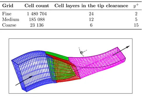
Table 1.: Computational grids.
Grid Cell count Cell layers in the tip clearance y+
Fine 1 480 704 24 2 Medium 185 088 12 5 Coarse 23 136 6 15 X Y Z
Figure 1.: View of the coarser grid.
Finally, the turbulent transport equation, solved in an uncoupled manner with respect to the main system of equations, is discretized through a second-order extension of Roe’s scheme with a minmod limiter. The solution technique applied to the turbulence equations is that of the baseline solver available in elsA (https://elsa.onera.fr) and will not be discussed further.
Research is in progress to extend the RBC formulation to turbulent transport equations using either a coupled or an uncoupled formulation (Content et al. (2013)).
3. Numerical results
The NASA Rotor 37, designed and tested originally by Reid and Moore (1978), is an isolated transonic axial compressor rotor with 36 blades. This case was initially included in a wider research program intended to cover a range of design parameters typical of aircraft turbine engine high-pressure compressor inlet stages. Much experimental data about rotor performance has been provided by Suder (1996). The test case has been presented in the AGARD Report 355 (1998) and used for the validation of CFD codes and turbulence models. All the data available for this case were measured with the rotor operating at the equivalent design rotational speed of 17188.7 rpm. A total of 13 sets of overall performance data were measured between the choked mass flow (measured value mchoke = 20.93 Kg/s) and the stall flow rate (equal to 0.925 of the
choke value, i.e. 19.36 Kg/s, according to experiments). Overall performance includes average total pressure ratio and adiabatic efficiency. Moreover, laser anemometer velocity data are also available for a mass flow rate of 0.98 mchoke.
Numerical computations were run using a series of three meshes made up by six structured blocks with conformal joins. The finest grid is clustered enough close to the walls so to be relevant for low-Reynolds computations. The coarsest grid uses values of y+ greater than 10. The main properties of these meshes are given in Tab. 1. The medium and coarse grids are obtained through successive agglomerations of neighbouring cells (eight by eight) of the finest one. A view of the coarsest grid is provided in Fig. 1.
Boundary conditions based on local 1D Riemann invariants are used at inlet and outlet boundaries. At the inlet, total pressure and temperature, as well as flow direction are imposed. At the outlet, the static pressure distribution (following radial equilibrium) is imposed and iteratively adjusted in order to achieve a prescribed target mass flow. The walls are assumed
to be adiabatic. Numerical computations were carried out with a CFL number equal to 5 for all cases. Computations were stopped once the relative variation in mass flow rate was lower than 0.5%, which is sufficient to make meaningful comparisons among numerical schemes. A total of 5 operation points distributed along the compressor characteristic were computed on the two coarser grids, whereas only two operation points were computed with the finest grid. Figure 2 shows a typical convergence history of the continuity equation residual and of the non-dimensional mass flow rate on the finest mesh for RBC3, compared to that of the standard Jameson scheme. For both schemes the residual drops about 4 orders of magnitude in 10000 iterations. Note that RBC3 seems to detect some form of physical instability in the shock/boundary layer interaction region, so that the residuals tend to stagnate around 10−4 after initial convergence. Time-accurate simulations are warranted in the future, to further investigate this phenomenon.
Numerical solutions were post-treated in order to extract the overall performance parameters, namely the average total pressure ratio,Pratio and the adiabatic efficiencyηis, defined as:
Pratio= Pt2 Pt1 ; ηis= ( Pt2 Pt1 )γ−1 γ − 1 Tt1 Tt2 − 1
wherePt andTt represent respectively the total pressure and temperature in the absolute
refer-ence frame, and the subscripts 1 and 2 stand for inlet and outlet of the computational domain, respectively. Computed and experimental results for both quantities and displayed in Fig. 3.
RBC schemes tend to underestimate the pressure ratio and adiabatic efficiency in comparison to measurements. Results progressively improve when refining the mesh, even if a complete agreement with experimental results is not reached. Previous studies have shown the difficulty of matching experimental data, due to multiple uncertainties in both flow models and experiments (see e.g. Chima (2009)). For this reason, hereafter we focus the discussion on the behaviours of different numerical schemes more than on comparisons with experimental data. An interesting result is that for RBC2 and, even more clearly, for RBC3, results obtained on the medium and fine grids are relatively close to each other (approximately to within 1.5%), which suggests that these schemes are close to mesh convergence. The coarse grid solution is very far from the fine mesh one, indicating that numerical errors are quickly reduced after the first grid refinement. On the contrary, the numerical solution provided by Jameson’s scheme varies significantly with mesh refinement: the pressure ratio is strongly over-estimated on the coarser grid (and the choke mass flow under-estimated), becomes fortuitously close to experimental data after the first mesh refinement, and tends to be underestimated on the finest grid. Differences between the solutions obtained on the two last grids are quite significant, suggesting poor mesh convergence of the numerical solution.
To investigate further the impact of numerical approximations on the computed rotor perfor-mance, an in-detail analysis of the numerical flow fields is carried out for operating conditions corresponding to 98% of the choke mass flow. Figure 4 provides an overall view of the computed flow field provided by the RBC3 scheme on the finest grid. The flow field is characterised by a bow shock upstream of the blade, as well as a passage shock leading to boundary layer separation. A complex shock structure is also present in the tip clearance. Figure 5 shows iso-Mach contours at the mid-plane computed on the finest grid with several schemes. Shock sharpness and size of the separation bubble vary according to the scheme in use: the sharpest shock and the greatest separation bubble are provided by RBC3, whereas Jameson’s scheme tends to smear shocks and leads to a smaller separation bubble. Note also that the high-accurate scheme predicts a higher maximum value of the Mach number in the computational field: precisely, maximum values of 1.907, 1.844, and 1.828, are obtained for RBC3, RBC2, and Jameson’s scheme, respectively.
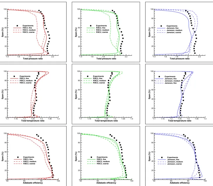
Differences among different schemes are more evident in Fig. 6, showing the nondimensional pressure distribution along the blade span for the finer grid. RBC3 and RBC2 give quite sim-ilar results, the shock at the suction side being captured slightly more sharply by RBC3. The solution given by Jameson scheme exhibits a different shock location and a much more smeared shock profile at the suction side, as well as an additional weak shock at the pressure side, around 15% of the chord: the different thickness and curvature of the bow shock upstream of the blade predicted by this more dissipative scheme alters somewhat the pressure distribution downstream. Figures 7 and 8 display the radial distributions of rotor performance at an axial station located 10.67 cm downstream of the blade leading edge. For this station, experimental measurements of the radial distributions of total pressure ratio, total temperature ratio, and adiabatic efficiency are available. As recommended in the AGARD Report 355 (1998), numerical solutions were mass-weighted in the azimuthal direction. Fig. 7 illustrates grid convergence for the three schemes under investigation; Fig. 8 compares the solutions of three schemes for the two finer grids. Experimental data show a region of low total pressure below 40% span, called a ”pressure deficit”. Most of the results previously shown in the litterature (AGARD Report 355 (1998); Dunham and Meauz´e (1998)) failed to predict this behaviour. Chima and Liou (2003) suggested that the low total pressure is an intrinsic feature of the rotor that tends to be smeared out by central-difference schemes used by many CFD codes. This is partly confirmed by the present results: on the two coarsest grids, Jameson’s central-difference scheme smears the pressure deficit, while over-predicting the total pressure in the upper part of the blade, leading to error compensation on the span-averaged pressure ratio. On the contrary, the RBC schemes capture the pressure deficit already on the medium grid. As previously observed for overall performance indicators, numerical solutions provided by RBC schemes converge more quickly than Jameson’s ones when the mesh is refined and predict well the pressure dimp already on the medium grid. RBC3 performs slightly better than RBC2, both in terms of grid convergence and in terms of agreement with experimental distributions. Similar remarks can be done on total temperature distributions. A finer grid is required for the lower-order scheme to capture the right trends, the absolute values being always less accurate than those of RBC schemes. Note that all schemes over-predict the total temperature downstream of the rotor above 90% span. According to AGARD Report 355 (1998); Chima (2009), this is also the case for many other CFD codes. The discrepancy maybe either due to modelling errors in CFD solver or to unrecognized errors in the experimental results. Note however that, at least for RBC schemes, agreement of the solution tends to improve when the computational grid is refined, suggesting that tip leakage flow features may be not resolved well enough on the present computational grids. Finally, adiabatic efficiency profiles appear to be less sensitive than pressure and temperature profiles to the numerical scheme in use. Nevertheless, the second-order central-difference scheme fails again to capture experimental radial trends of the efficiency distribution on the two coarsest grids.
To complete the discussion, the computational cost of RBC schemes is compared to the cost of the baseline scheme. The present computations were run on a PC using X5660 Xeon exacore processors with a clock frequency of 2.8Ghz. Computations run with theelsA code were
paral-lelized on two cores using MPI. With this configuration, the computational cost per iteration and per point was of about 0.0125 sec using Jameson’s scheme. Global computational costs of a Rotor 37 calculation are those required to achieve an almost converged mass flow. All of the schemes achieve the required tolerance level within almost the same number of iterations (about 3000). RBC schemes are more expensive than Jameson’s scheme in terms of operation count: precisely, the computational costs per iteration and per point of RBC2 and RBC3 are about 1.8 and 2.2 times greater, respectively. Nevertheless, RBC schemes are clearly more accurate, since they provide almost grid-converged solutions using about 1/8 of the mesh cells required by the baseline scheme. RBC3 is slightly more expensive than RBC2, mainly because of the computation of weighting coefficients, but the extra cost is compensated by a somewhat better
accuracy. It is concluded that, for this steady RANS case, using a well-designed, low dissipative scheme has a stronger effect in terms of improved accuracy of the solution than increasing the formal order of accuracy, so that satisfactory results can be obtained already for a RBC scheme of 2nd-order accuracy. This conclusion is likely to change in favour of the 3rd-order scheme for unsteady RANS and LES computations. Further research will focus on the application of high-order RBC schemes to scale-resolving unsteady simulations.
4. Conclusions
Numerical simulations of the Rotor 37 test case are carried out at several operating conditions us-ing RBC schemes of 2nd and 3rd-order accuracy. It is worthy stressus-ing the novelty of computus-ing such challenging complex flow fields using an almost 3rd-order accurate scheme. Present results prove, first of all, the feasibility of high-order methods for computing this kind of flows. Compar-isons of numerical solutions predicted by RBC schemes for increasing degrees of mesh resolution with those of the baseline solver in elsA, namely, Jameson’s scheme, show that RBC schemes provide almost grid converged results on computational grids that are 8 times coarser. Moreover, computational results are in reasonably good agreement with experimental data, showing that the use of accurate schemes and/or fine enough meshes improves solution predictivity even using a relatively simple turbulence model (here, Spalart–Allmaras).
Thanks to the use of coarser grids, RBC schemes reduce the computational cost required to achieve mesh-converged solutions by at least a factor between 2 and 4 compared to standard methods, even if their CPU cost per iteration and per point is 1.8 to 2.2 times higher, according to the chosen order of accuracy. Specifically, if only steady computations are required, RBC2 provides a good compromise between accuracy, memory loading, robustness, and computational cost. On the other hand, two-dimensional unsteady computations (Michel et al. (2011)) of tur-bomachinery flows show that at least 3rd-order accuracy is required for unsteady computations. Numerical applications of RBC3 to unsteady 3D flows are warranted in the near future.
Acknowledgements
This research has been done within the framework of the European project IDIHOM (Industrial-ization of High Order Methods) which aims to promote the use of high-order numerical methods by the European aerospace industry.
References
Dunham J., editor, 1998. “CFD validation for propulsion system components”. AGARD Advisory Report AR-355.
Ameri A.A., 2010. “NASA Rotor 37 CFD code validation”. NASA CR-2010-216235
Beam R., Warming R.F., 1976. “An implicit finite difference algorithm for hyperbolic systems in conser-vation laws”. J Comp Phys 22: 87–110.
Chima R. K., 2009. “SWIFT code assessment for two similar transonic compressors”. NASA TM-2009-215520
Chima R. K., Liou M.-S., 2003. “Comparison of the AUSM+ and H-CUSP Schemes for Turbomachinery Applications”. AIAA Paper 2003-4120 and NASA TM-2003-212457.
Content C., Outtier P.Y., Cinnella P., 2013. “Coupled/Uncoupled solutions of RANS equations using a Jacobian-free Newton-Krylov method”. AIAA Paper 2013-2423.
Corre C., Lerat A., 2008. “High-order residual-based compact schemes for advection-diffusion problems”.
Comp Fluids 37: 505–519.
Corre C., Hanss G., Lerat L., 2005. “A Residual-Based Compact scheme for the unsteady compressible Navier-Stokes equations”. Comp Fluids 34: 561–580
iteration R e s id u a l, L 2 n o rm 2000 4000 6000 8000 10000 101 102 103 104 RBC3 Jameson iteration M a s s fl o w 0 500 1000 1500 2000 12 14 16 18 20 22 RBC3 Jameson
Convergence tolerance range
Figure 2.: Sample convergence histories, fine grid computation, 98% choke conditions.
Dunham J., Meauz´e G., 1998. “An AGARD working group study of 3D Navier–Stokes codes applied to
single turbomachinery blade rows”. ASME Paper 98-GT-50 https://elsa.onera.fr
Gomar A., Gourdain N., Dufour G., 2011. “High-fidelity simulation of the turbulent flow in a transonic compressor”. In : 9th European Turbomachinery Conference–ETC, 21-25 May 2011, Istanbul, Turkey. Grimich K., Cinnella P., Lerat A., 2013. “Spectral properties of high-order Residual-Based Compact
schemes for unsteady compressible flows”. J Comp Phys 235: 142–162.
Grimich K., Michel B., Cinnella P., Lerat A., 2013. “Generalized finite volume formulation of a third-order Residual-Based Compact scheme for unsteady flow computations”. Comp Fluids Accepted paper. DOI: 10.1016/j.compfluid.2013.12.016.
Hah C., 2009. “Large Eddy Simulation of transonic flow in NASA Rotor 37” NASA TM-2009-215627. Jameson A., Turkel E., 1981. “Implicit schemes and LU decompositions”. Math Comput 37: 385–398. Lerat A., Corre C., 2001. “A Residual-Based Compact Scheme for the Compressible Navier-Stokes
Equa-tions”. J Comp Phys 170: 642–675.
Lerat A., Corre C., 2002. “Residual-Based Compact schemes for multidimensional hyperbolic systems of conservation laws”. Comp Fluids 31: 639–661.
Lerat A., Corre C., 2006. “Higher order Residual-Based Compact schemes on structured grids”. 34th
Comput. Fluid Dyn. Course, von Karman Institute for Fluid Dynamics VKI LS 2006-1: 1-111.
Lerat, A., Corre, C., Hanss, G., 2002. “Efficient high-order schemes on non-uniform meshes for multi-D compressible flows”. In: Frontiers of Computational Fluid multi-Dynamics 2002, edited by multi-D.Caughey, M.Hafez, 89–109. Singapore: World Scientific.
Lerat A., Grimich K., Cinnella P., 2013. “On the design of high order Residual-Based dissipation for unsteady compressible flows”. J Comp Phys 235: 32–51
Michel B., “Contribution `a la simulation num´erique efficace dess ´ecoulements dans les prises d’air
super-soniques”. PhD thesis, Arts et M´etiers ParisTech, Paris.
Michel B., Cinnella P., Lerat A., 2011. “Multiblock Residual-Based Compact Schemes for the computation of complex turbomachinery flows”. Int J Engin Sys Model Simulation 3: 2–15.
Reid L., Moore R.D., 1978. “Design and Overall Performance of Four Highly-Loaded, High Speed Inlet Stages for an Advanced, High Pressure Ratio Core Compressor”, NASA TP-1337.
Suder K.L., 1996. “Experimental Investigation of the Flow Field in a Transonic, an Axial Flow Compressor With Respect to the Development of Blockage and Loss”, NASA TM 107310.
Tartinville B., Hirsch C., 2006. “Rotor 37”. In FLOWMANIA – A European initiative on flow physics
modelling, edited by W. Haase, B. Aupoix, U. Bunge, D. Schwamborn. Notes on Numerical Fluid
Mass Flow (Kg/s) P re s s u re ra ti o 19 19.5 20 20.5 21 1.6 1.8 2 2.2 Experimental data RBC3 scheme, fine grid RBC3 scheme, medium grid RBC3 scheme, coarse grid
Mass Flow (Kg/s) E ff ic ie n c y (% ) 19 19.5 20 20.5 21 70 72 74 76 78 80 82 84 86 88 90 Experimental data RBC3 scheme, fine grid RBC3 scheme, medium grid RBC3 scheme, coarse grid
Mass Flow (Kg/s) P re s s u re ra ti o 19 19.5 20 20.5 21 1.6 1.8 2 2.2 Experimental data RBC2 scheme, fine grid RBC2 scheme, medium grid RBC2 scheme, coarse grid
Mass Flow (Kg/s) E ff ic ie n c y (% ) 19 19.5 20 20.5 21 70 72 74 76 78 80 82 84 86 88 90 Experimental data RBC2 scheme, fine grid RBC2 scheme, medium grid RBC2 scheme, coarse grid
Mass Flow (Kg/s) P re s s u re ra ti o 19 19.5 20 20.5 21 1.6 1.8 2 2.2 Experimental data Jameson scheme, fine grid Jameson scheme, mediumgrid Jameson scheme, coarse grid
Mass Flow (Kg/s) E ff ic ie n c y (% ) 19 19.5 20 20.5 21 70 72 74 76 78 80 82 84 86 88 90 Experimental data Jameson scheme, fine grid Jameson scheme, medium grid Jameson scheme, coarse grid
Figure 3.: Rotor 37 performance maps for several schemes and grid resolutions. Left: pressure ratio; right: isentropic efficiency.
X Y
Z
Figure 4.: Overall view of the flow field (98% choke conditions). Mach number distribution at midplane, and stream ribbons colored by the Mach number. RBC3 scheme.
M 1.85 1.75 1.65 1.55 1.45 1.35 1.25 1.15 1.05 0.95 0.85 0.75 0.65 0.55 0.45 0.35 0.25 0.15 0.05 M 1.85 1.75 1.65 1.55 1.45 1.35 1.25 1.15 1.05 0.95 0.85 0.75 0.65 0.55 0.45 0.35 0.25 0.15 0.05 M 1.85 1.75 1.65 1.55 1.45 1.35 1.25 1.15 1.05 0.95 0.85 0.75 0.65 0.55 0.45 0.35 0.25 0.15 0.05 RBC3 RBC2 Jameson
Figure 5.: Mach number distribution at compressor’s midplane for several schemes. Fine grid computation. x/c p /p 0 in, re l 0 0.2 0.4 0.6 0.8 1 0.2 0.4 0.6 0.8 1 1.2 RBC3 RBC2 Jameson Pressure side Suction side
Figure 6.: Non-dimensional pressure distribution along the midspan section. Comparison of three schemes, fine grid.
Total pressure ratio S p a n (% ) 1.4 1.6 1.8 2 2.2 0 20 40 60 80 100 Experiments RBC3, fine RBC3, medium RBC3, coarse
Total pressure ratio
S p a n (% ) 1.4 1.6 1.8 2 2.2 0 20 40 60 80 100 Experiments RBC2, fine RBC2, medium RBC2, coarse
Total pressure ratio
S p a n (% ) 1.4 1.6 1.8 2 2.2 0 20 40 60 80 100 Experiments Jameson, fine Jameson, medium Jameson, coarse
Total temperature ratio
S p a n (% ) 1.1 1.15 1.2 1.25 1.3 1.35 1.4 0 20 40 60 80 100 Experiments RBC3, fine RBC3, medium RBC3, coarse
Total temperature ratio
S p a n (% ) 1.1 1.15 1.2 1.25 1.3 1.35 1.4 0 20 40 60 80 100 Experiments RBC2, fine RBC2, medium RBC2, coarse
Total temperature ratio
S p a n (% ) 1.1 1.15 1.2 1.25 1.3 1.35 1.4 0 20 40 60 80 100 Experiments Jameson, fine Jameson, medium Jameson, fine Adiabatic efficiency S p a n (% ) 40 60 80 100 0 20 40 60 80 100 Experiments RBC3, fine RBC3, medium RBC3, coarse Adiabatic efficiency S p a n (% ) 40 60 80 100 0 20 40 60 80 100 Experiments RBC2, fine RBC2, medium RBC2, coarse Adiabatic efficiency S p a n (% ) 40 60 80 100 0 20 40 60 80 100 Experiments Jameson, fine Jameson, medium Jameson, coarse
Figure 7.: Radial performance distributions for several schemes and grid resolutions. Mesh con-vergence study
Total pressure ratio S p a n (% ) 1.4 1.6 1.8 2 2.2 0 20 40 60 80 100 Experiments RBC3, medium RBC2, medium Jameson, medium
Total pressure ratio
S p a n (% ) 1.4 1.6 1.8 2 2.2 0 20 40 60 80 100 Experiments RBC3, fine RBC2, fine Jameson, fine
Total temperature ratio
S p a n (% ) 1 1.05 1.1 1.15 1.2 1.25 1.3 1.35 1.4 0 20 40 60 80 100 Experiments RBC3, medium RBC2, medium Jameson, medium
Total temperature ratio
S p a n (% ) 1 1.05 1.1 1.15 1.2 1.25 1.3 1.35 1.4 0 20 40 60 80 100 Experiments RBC3, fine RBC2, fine Jameson, fine Adiabatic efficiency S p a n (% ) 40 60 80 100 0 20 40 60 80 100 Experiments RBC3, medium RBC2, medium Jameson, medium Adiabatic efficiency S p a n (% ) 40 60 80 100 0 20 40 60 80 100 Experiments RBC3, fine RBC2, fine Jameson, fine
Figure 8.: Radial performance distributions for several schemes and grid resolutions. Comparisons among different schemes on the medium (left) and finer (right) grids.