Science Arts & Métiers (SAM)
is an open access repository that collects the work of Arts et Métiers Institute of
Technology researchers and makes it freely available over the web where possible.
This is an author-deposited version published in: https://sam.ensam.eu Handle ID: .http://hdl.handle.net/10985/7720
To cite this version :
Muhammad SADIQ, Raphaël PESCI, Mohammed CHERKAOUI - Impact of Thermal Aging on the Microstructure Evolution and Mechanical Properties of Lanthanum-Doped Tin-Silver-Copper Lead-Free Solders - Journal of Electronic materials - Vol. 42, n°3, p.492-501 - 2013
Any correspondence concerning this service should be sent to the repository Administrator : archiveouverte@ensam.eu
Impact of Thermal Aging on the Microstructure Evolution
and Mechanical Properties of Lanthanum-Doped
Tin-Silver-Copper Lead-Free Solders
MUHAMMAD SADIQ,1,2,3,5RAPHAE¨ L PESCI,4and MOHAMMED CHERKAOUI1,2,3
1.—George W. Woodruff School of Mechanical Engineering, Georgia Institute of Technology, 801 Ferst Drive NW, Atlanta, GA 30332, USA. 2.—University of Lorraine, LEM3 UMR CNRS 7239, ıˆle du Saulcy, 57045 Metz, France. 3.—UMI 2958-Georgia Tech-CNRS Georgia Tech Lorraine, 57070 Metz, France. 4.—ENSAM-Arts et Me´tiers ParisTech, LEM3 UMR CNRS 7239, 4 rue Augustin Fresnel, 57078 Metz, France.5.—e-mail: msadiq3@gatech.edu
An extensive study is made to analyze the impact of pure lanthanum on the microstructure and mechanical properties of Sn-Ag-Cu (SAC) alloys at high temperatures. Different compositions are tested; the temperature applied for the isothermal aging is 150°C, and aging times of 10 h, 25 h, 50 h, 100 h, and 200 h are studied. Optical microscopy with cross-polarized light is used to follow the grain size, which is refined from 8 mm to 1 mm for as-cast samples and is maintained during thermal aging. Intermetallic compounds (IMCs) present inside the bulk Sn matrix affect the mechanical properties of the SAC alloys. Due to high-temperature exposure, these IMCs grow and hence their impact on mechanical properties becomes more significant. This growth is followed by scanning electron microscopy, and energy-dispersive spectroscopy is used for elemental mapping of each phase. A significant refinement in the average size of IMCs of up to 40% is identified for the as-cast samples, and the coarsening rate of these IMCs is slowed by up to 70% with no change in the interparticle spacing. Yield stress and tensile strength are determined through tensile testing at 20°C for as-cast samples and after thermal aging at 150°C for 100 h and 200 h. Both yield stress and tensile strength are increased by up to 20% by minute lanthanum doping.
Key words: Lanthanum, SAC alloys, intermetallic compounds, aging temperature, aging time
INTRODUCTION
Sn-Pb solder has long been used in the electronics industry, but due to its toxic nature and environ-mental effects, certain restrictions are made on its use by the European RoHS directive, and therefore, many researchers are looking to replace it. This is because Pb and Pb-containing compounds, as cited by the US Environmental Protection Agency (EPA), is one of the top 17 chemicals posing the greatest threat to human beings and the environment.1
The
new lead-free solders are mostly Sn-containing binary and ternary alloys.2 Due to their better thermomechanical properties, SAC alloys are con-sidered as the best choice.2,3 However, because of their coarse microstructure, iron (Fe), cobalt (Co), and nickel (Ni) have been used as refining elements, and their effects on the microstructure have been investigated.4 Many combinations of, e.g., indium (In), antimony (Sb), bismuth (Bi), copper (Cu), and silver (Ag) are also used as alloying elements.2 Extensive knowledge and understanding of the mechanical behavior of the emerging generation of lead-free solders is required to satisfy the demands of structural reliability.
Rare-earth (RE) elements are used in different studies and are considered as the vitamins of metals because of their special surface-active properties which help in overall refinement of the microstruc-ture and hence improve the mechanical proper-ties.5–10They are widely used in Sn-Zn, Sn-Ag, and Ag-Cu alloys.6–8Lanthanum (La) is considered as a good additive due to its lower cost, wide availability, and low melting point4 as compared with other RE elements.
REs are used to control the growth of IMCs at high temperatures and hence play a major role in improving the overall mechanical properties of SAC alloys, but overdoping can deteriorate the solder mechanical properties. They have been used in dif-ferent studies; e.g., cerium (Ce) and lanthanum (La) are used in Sn-9Zn alloys.7 Lutetium (Lu) is also
used in many studies to improve Sn-Au and Sn-Ag solder alloys.7 In Ref. 8, addition of small traces of RE elements reduced the size of Ag3Sn and Cu6Sn5
IMCs, while in Refs.6,11 the impact of lanthanum on the microstructure evolution due to isothermal aging was studied for eutectic Sn-3.5Ag alloy. In Ref.12, the impact of long-term isothermal aging is studied for the growth of intermetallic interfacial
layers on Sn-Ag and Sn-Pb eutectic solders on Cu substrates. Similarly, in Ref. 13, the impact of iso-thermal aging on RE-doped Sn-Cu alloys was stud-ied. Hao et al.14 systematically investigated the evolution of microstructure and IMCs for SAC sol-der modified with trace amounts of the rare-earth element Er (addition of 0.15 wt.% Er to SAC387) during isothermal aging. All these elements refine the grain size, leading to a fine microstructure which ultimately improves the mechanical proper-ties of SAC lead-free solders, including the yield stress and tensile strength, thus increasing solder joint reliability.15,16 In Ref. 17, the impact of iso-thermal aging on mechanical properties of SAC alloys was studied.
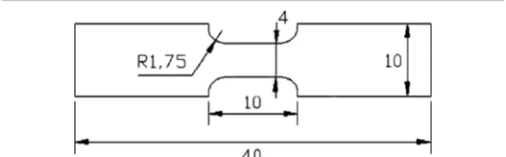
Fig. 1. Dog-bone-shaped specimen for tensile tests.
Modern electronic devices are subjected to severe thermal conditions varying up to 175°C. Moreover, many assemblies are composed of different electronic materials with a wide range of thermal expansion coefficients, which causes extra stress generation. Therefore, different compositions of La are tested in this study to identify an optimum SAC-La alloy, and mechanical properties are determined in varying environmental conditions.
The high temperature selected for aging is 150°C, and aging times of 10 h, 25 h, 50 h, 100 h, and 200 h are tested. Specimens are exposed to these conditions in a furnace after polishing and etching. They are analyzed at the end of each aging time and are put back into the furnace after analysis. Ele-mental mapping and chemical composition of each phase are achieved using an SEM equipped with an EDS system, and grain size is calculated using an optical microscope with cross-polarized light. The gauge area is focused on during the entire period of study.
The main focus of this work is to provide a quan-titative analysis of the microstructure evolution under heat treatment of Sn-Ag-Cu lanthanum-doped alloys and its impact on mechanical properties. IMC particle size (average diameter), grain size, and interparticle spacing measurements have been car-ried out at different aging times at 150°C with dif-ferent doping of lanthanum.
Since exposure of solder joints to high tempera-tures causes IMC particle coarsening, the mechan-ical properties may also be affected and early failure
can be expected. As-cast samples and samples exposed to temperature of 150°C during 100 h and 200 h are then analyzed to determine the impact of thermal aging on mechanical properties through tensile testing at 20°C.
EXPERIMENTAL PROCEDURES
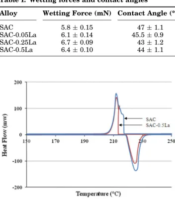
Solder alloys were prepared from pure metals, in the form of 200 g ingots with the following composi-tions (wt.%): Sn-3.0Ag-0.5Cu, Sn-3.0Ag-0.5Cu-0.01La, Sn-3.0Ag-0.5Cu-0.05La, Sn-3.0Ag-0.5Cu-0.25La, and Sn-3.0Ag-0.5Cu-0.5La. A three-part casting die, composed of two parts in aluminum and a central steel plate, was used to achieve ‘‘cast by melt’’ die-casting to make dog-bone-shaped tensile specimens. The front part of the die contains the path for the flow of molten alloy. The central plate contains five cavities for sample casting which are designed in a Table I. Wetting forces and contact angles
Alloy Wetting Force (mN) Contact Angle (°)
SAC 5.8 ± 0.15 47 ± 1.1
SAC-0.05La 6.1 ± 0.14 45.5 ± 0.9
SAC-0.25La 6.7 ± 0.09 43 ± 1.2
SAC-0.5La 6.4 ± 0.10 44 ± 1.1
Fig. 3. DSC curves for SAC and SAC-0.5La alloys.
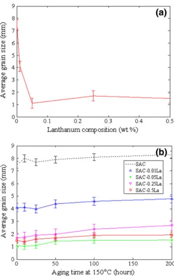
Fig. 4. Average IMC particle size versus La composition for as-cast (a) and thermally aged samples (b).
Table II. Interparticle spacing
La (wt.%) 0 0.01 0.05 0.25 0.5
dog-bone shape. The back side of the die is used to tighten the plate to the front side and also provide fins to expedite the cooling rate during the solidifi-cation process. A temperature of 260°C is applied in the oven, and the die is heated for about 45 min before putting the molten metal into it. The 200 g ingots are put into a crucible and then placed in the oven at 260°C for about 25 min. Water at tempera-ture of 15°C is used for quenching; the cooling rate of the specimens was measured with a K-type thermocouple. Only a small part of the die is dipped into the water to obtain a slow cooling rate of about 3°C/s, which is close to the actual reflow soldering process. The thickness of the resulting specimens is 2 mm. One of these cast specimens is shown in Fig.1; all dimensions are in mm.
Differential scanning calorimetry (DSC) tests were performed first to investigate the impact of lanthanum doping on the melting temperature of SAC alloys. The electrical resistivity of the SAC and SAC-La doped alloys was also measured using a four-point method for as-cast and thermally aged samples.
For quantitative microscopy, specimens of each composition were mechanically polished with silicon discs as well as 6-micron, 3-micron, and 1-micron diamond pastes. Chemical etching was performed
for a few seconds using 5% hydrochloric acid/95% ethanol solution.
Quasistatic tensile tests at strain rate of 2 9 10 4s 1 were finally carried out with an MTS tensile machine equipped with a 5 kN load cell to determine the mechanical properties as a function of lanthanum doping for all compositions mentioned above except Sn-3.0Ag-0.5Cu-0.01La.
RESULTS AND DISCUSSION
The microstructure of the SAC alloys studied is composed of a soft Sn matrix and hard IMCs of Ag and Cu with Sn.16Figure2shows an SEM image of
a SAC alloy: the black zone is the matrix that is mainly composed of Sn, and the white particles are the IMCs. These IMCs, rich in Ag and Cu, are brittle in nature in comparison with the soft Sn matrix and affect the mechanical properties of lead-free solders.13The size of these particles depends on many parameters such as alloy composition, cooling rate, and environmental conditions during service with temperature up to 175°C and aging time up to several hundred hours. In order to constrain the size of these IMCs, many researchers attempted a change in the cooling rate during the solidification process.18,19 A fast cooling rate can generate a fine Fig. 5. (a) SEM image and EDS elemental mappings of (b) Sn, (c) Ag, and (d) Cu for the as-cast SAC sample.
microstructure, but in many cases, this is not fea-sible because of the large thermal stresses in the substrates.
Lanthanum is well known for its surface-active properties.11 During solidification, it moves to the free surface. In the SEM micrographs, small pores are observed only in doped alloys for the unpolished samples. EDS study also showed that lanthanum is uniformly distributed over the free surface.20 The presence of lanthanum at the natural surface has
many advantages. When this alloy is used as a der joint, the elemental lanthanum in the bulk sol-der alloy at the interface will improve the wetting behavior of the solder alloy by creating chemical bonds with other materials.11 Extensive wetting balance test study has been performed at 250°C and 260°C by the authors,20 and it was observed that lanthanum doping increases wetting forces and reduces contact angles. TableI summarizes the wetting force and contact angle after performing 10 tests for each composition. Rosin mildly activated (RMA) flux was used. The results are quite consis-tent with Ref.13.
DSC tests were conducted between the two peaks of 20°C and 300°C for both SAC and SAC-La doped alloys with a heating and cooling rate of 5°C/min. DSC curves are presented in Fig.3. It is seen that there is no significant change in the melting temperature (starts at 217°C and ends at 230°C) between the undoped and maximum-doped SAC alloy, which is consistent with Ref.11. Finally, the Fig. 6. (a) SEM image and EDS elemental mappings of (b) Sn, (c) Ag, and (d) Cu for SAC-La after 100 h thermal aging.
Table III. Atomic composition of IMCs
IMC
Atomic %
Sn Ag Cu
Ag3Sn 74 ± 0.7 26 ± 0.7 9
electrical resistivity measurements show that lan-thanum doping has no influence on either as-cast or thermally treated samples.20 The values for all samples with all test conditions are typically in the range of 10 lX cm to 15 lX cm.
Particle Size
An SEM FEG Jeol 7001F was used to collect images for each composition at different resolutions,
in the initial state and after different aging times. The as-cast and thermally aged SEM images for Sn-3.0Ag-0.5Cu and Sn-Sn-3.0Ag-0.5Cu-0.5La alloys are shown in Fig.2. With thermal aging, coarsening of both Ag-Sn and Cu-Sn IMCs takes place, at a rate depending on the temperature applied and aging time. It could be easily concluded from the micro-graphs that the coarsening rate for lanthanum-doped alloy is much slower than for the unlanthanum-doped alloy.
Fig. 7. (a) SEM micrograph and EDS elemental mappings of (b) Sn and (c) La of SAC-La alloy.
Microstructure evolution is observed in terms of the IMC average particle size, its volume fraction, and the interparticle spacing. These measurements were done as a function of aging time, aging tem-perature, and lanthanum composition. ImageJ software was used to measure the average particle size at every aging interval. At least three SEM images of every composition were provided for measurements using three different magnifications: 8509, 25009, and 50009. The particle size was also measured manually in terms of average surface area using ASM handbook standards21supported by
ImageJ analysis. The results are plotted in Fig. 4a as a function of lanthanum doping and in Fig.4b as a function of aging time at 150°C.
Stoichiometric calculations have shown that the volume fraction of IMCs in Sn-Ag alloy is around 0.07 in general.22Since the amount of La doping is quite small in the current work, the volume fraction of IMCs can be considered as close to 0.07. If the IMCs are assumed to be spherical and uniformly distributed in the eutectic region, as also considered in Ref. 11, then the interparticle spacing (side-to-side distance) can be calculated from the volume
fraction of eutectic region. The results are presented in TableII. It is observed that this spacing does not change a lot with La doping. This validates the fact that La doping reduces the size of the particles, which inevitably increases the number of particles to keep the same interparticle spacing. Moreover, if the interparticle spacing is not changed, this justi-fies the fact that the eutectic region would be increased for higher La doping.
Figure4a indicates a drastic decrease in the par-ticle size due to lanthanum doping, whereas Fig.4b shows that the coarsening rate of these IMCs is smaller for the lanthanum-doped alloys than for the undoped alloy.
As previously mentioned, the IMCs consist of Ag-Sn and Cu-Ag-Sn. An Oxford EDS system in the SEM enabled elemental mapping for each specimen. The spatial distribution of Ag, Cu, and Sn could be visualized in the IMCs, as shown in Fig.5. To follow the growth of these IMCs, another SEM image and spatial distribution of these elements are provided in Fig.6 for a 100 h thermally aged specimen. The Cu-based IMCs are much darker than Ag-based IMCs, as also reported in Ref.23, and are therefore easily distinguished and confirmed by the EDS for two different zones as shown in Fig.6. About 25 IMCs were analyzed, and an average measurement for the atomic % is provided in TableIII. The atomic % may not correspond to the exact ratio for Ag3Sn
and Cu6Sn5 IMCs due to the limitation of our
experimental setup, which considers more Sn to a depth of a few microns, which may not be the actual depth of these IMCs.
Thermal aging causes the evolution of both Ag3Sn
and Cu6Sn5 IMCs, and this process is governed by
r3µ t, where r is the average radius of the IMC particles and t is the isothermal aging time.23,24 Both types of particle coarsen at different rates due to the different rate-controlling mechanisms. The diffusion rate of Cu into Sn is higher than the dif-fusion rate of Ag into Sn.23Therefore, with time, the coarsening of Cu6Sn5 is much greater than that of
Ag3Sn24, due to which the Cu6Sn5 IMCs can be
easily differentiated from Ag3Sn IMCs. In Ref.10, it
was reported that the size of Cu6Sn5IMCs is much
larger than that of Ag3Sn IMCs in SAC alloys. The
EDS mapping for SAC-La alloy after thermal aging is presented in Fig.6. Contrary to Ag3Sn particles,
which show a normal increase with submicron size, the thermal evolution of Cu6Sn5 IMCs shows a
sig-nificant growth up to a few microns. This is consis-tent with Ref.10. The rapid growth starts after 50 h of thermal aging at 150°C.
It is reported in Refs.6,11that La may be present in elemental form, but they could not identify it due to experimental limitations. In this work, however, La was confirmed to be present in the form of oxides in the bulk alloy. EDS elemental mappings were performed for La and other elements and are pre-sented in Fig.7 along with the SEM micrograph. This form is dispersed thoroughly in the bulk Fig. 9. Average grain size versus La composition for as-cast (a) and
alloy.5,8Due to the small size of these oxides, they have not been determined exactly.
Grain Size
Grain size was measured for the as-cast samples and then continuously followed during thermal aging. Figure8shows grain size images for Sn-Ag-Cu and Sn-Ag-Sn-Ag-Cu-0.05La as-cast samples. Optical microscopy with cross-polarized light was used for this study, in which grains can be observed as dif-ferent shades. A significant decrease in grain size, due to the addition of lanthanum, can be seen.
Grain size, as a function of lanthanum composi-tion, is plotted in Fig. 9a. A huge refinement is observed. Figure9b describes the grain size as a function of aging time at high temperature. Since the number of grains is not large, error bars are provided in both plots. It is important to note that the grain size for the undoped alloy is too large and only one grain boundary is observed in the gauge area. Hence, the grain size is assumed to be 8 mm as given in Fig. 9a. It is also observed that the alloy composition with the smallest grain size is SAC-0.05La. This is consistent with the work performed Fig. 10. Stress versus La composition for (a) as-cast, (b) 100 h thermally aged, and (c) 200 h thermally aged samples.
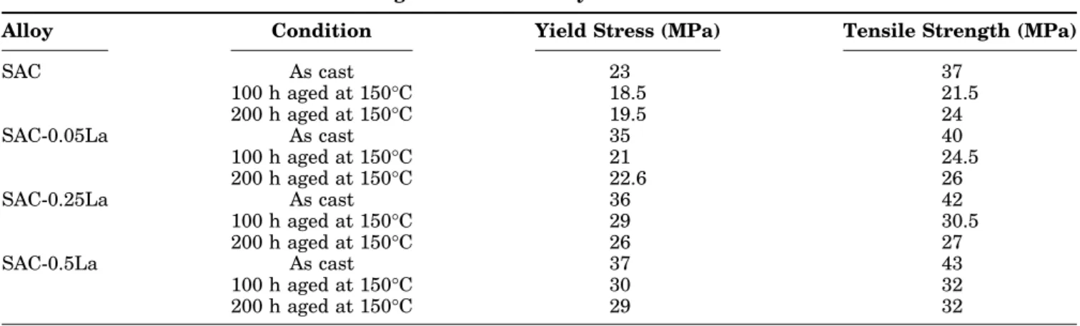
Table IV. Yield stress and tensile strength of SAC-La alloys
Alloy Condition Yield Stress (MPa) Tensile Strength (MPa)
SAC As cast 23 37 100 h aged at 150°C 18.5 21.5 200 h aged at 150°C 19.5 24 SAC-0.05La As cast 35 40 100 h aged at 150°C 21 24.5 200 h aged at 150°C 22.6 26 SAC-0.25La As cast 36 42 100 h aged at 150°C 29 30.5 200 h aged at 150°C 26 27 SAC-0.5La As cast 37 43 100 h aged at 150°C 30 32 200 h aged at 150°C 29 32
by Pei and Qu6,11for Sn-3.5Ag alloy with similar La doping. Previous studies20 found that, due to the pinning effect of IMCs, thermal aging does not affect the grain size in the undoped alloys. Figure 9b shows that almost no change in grain size occurred due to thermal aging. It can be concluded that lan-thanum doping not only refines the grain size but also restricts its growth at high temperatures. This is consistent with Ref.11. This refinement is due to the particular effect of lanthanum adsorption at different planes in the SAC alloys.8,13,25
Mechanical Properties
Figure10a shows the yield stress and tensile strength for the as-cast samples at room tempera-ture. A significant increase in both yield stress and tensile strength is observed. This is consistent with Ref. 16, in which an increase in tensile strength is investigated for Sn-0.7Cu, Sn-3.5Ag, and Sn-9Zn alloys due to RE elements (mainly Ce and La). On the other hand, an increase in La doping also leads to a decrease in elongation to failure. This may be due to an increase in the quantity of hard, RE-bearing particles.8,13In Ref.26, it is shown that lanthanum results in the formation of LaSn3
com-pounds. The average microhardness of this phase, in a slowly cooled alloy, has a high value of 48 HV as compared with the average microhardness of the matrix of 13.5 HV.9
The evolution of yield stress and tensile strength for 100 h and 200 h aging at 150°C are given in Fig.10b and c, respectively; all values are summa-rized in TableIV. The increase in yield stress and tensile strength due to RE doping in tin-based alloys is quite consistent with Ref.27.
Thermal coarsening greatly affected the micro-structure of the SAC alloys. We can see a significant decrease in both yield stress and tensile strength from the as-cast alloys to thermally aged alloys. This is because of the IMC growth, which causes early failure and reduces solder joint reliability. In all three cases, the mechanical properties of the doped solders are significantly higher than those of the undoped alloys. Even an increase of 2 MPa could be appreciable, since this corresponds to a 10% increase in the yield stress of 20 MPa.
Since creep tests are conducted under constant stress, less than the yield stress, an increase in the yield stress would increase the gap between the applied stress and the yield stress of the material. Thus, it is expected that La doping will increase the creep life of SAC alloys, as also presented by many researchers.9,13,28
CONCLUSIONS
Doped SAC alloys have been studied to determine the influence of lanthanum on their microstructure evolution and mechanical properties at high tem-perature. Several conclusions can be made. The addition of lanthanum drastically reduces the IMC
particle size. It also controls the growth of these IMC particles during thermal aging. It leads to a huge refinement of grains for the as-cast specimens, but no evolution is observed after thermal aging. There is no significant increase in the interparticle spacing. A significant increase of yield stress and tensile strength with lanthanum doping is observed for as-cast and thermally aged specimens. Thus, lanthanum refines the microstructure, reduces the drastic effects of IMCs, and hence improves the mechanical properties of SAC solders.
ACKNOWLEDGEMENTS
The authors would like to thank Ste´phanie Blanc (Electrical Engineer at Schlumberger) for her useful contribution to the project, Claude Guyomard and Olivier Naegelen (Arts et Me´tiers ParisTech) for the die design and sample casting, respectively, and Jean-Marc Raulot for his enriching discussions.
CONFLICT OF INTEREST
The authors declare that they have no conflict of interest.
REFERENCES
1. E.P. Wood and K.L. Nimmo, J. Electron. Mater. 23, 709–713 (1994).
2. D.Q. Yu, J. Zhao, and L. Wang, J. Alloys Compd. 376, 170– 175 (2004).
3. M.A. Rist, W.J. Plumbridge, and S. Cooper, J. Electron. Mater. 35, 1050–1058 (2006).
4. M.A. Dudek, R.S. Sidhu, and N. Chawla, J. Mater. 6, 57–62 (2006).
5. I.E. Anderson, J.C. Foley, B.A. Cook, J. Harringa, R.L. Terpstra, and O. Unal, J. Electron. Mater. 30, 1050–1059 (2001).
6. M. Pei and J. Qu, Proceedings of the 57th Electronic Com-ponents and Technology Conference, Reno, NV, 2007, pp. 198–204.
7. Anon, Photonics Spectra, 36(5), 139 (2002).
8. Z.G. Chen, Y. Shi, Z. Xia, and Y. Yan, J. Electron. Mater. 32, 235–243 (2003).
9. C.M.L. Wu, D.Q. Yu, C.M.T. Law, and L. Wang, J. Mater. Res. 31, 3146–3154 (2002).
10. T. Chen and I. Dutta, J. Electron. Mater. 37, 347–354 (2008). 11. M. Pei and J. Qu, J. Electron. Mater. 37, 331–338 (2008). 12. S. Choi, T.R. Bieler, J.P. Lucas, and K.N. Subramanian,
J. Electron. Mater. 28, 1209–1215 (1999).
13. C.M.L. Wu, D.Q. Yu, C.M.T. Law, and L. Wang, Mater. Sci. Eng. R 44, 1–44 (2004).
14. H. Hao, Y. Shi, Z. Xia, Y. Lei, and F. Guo, J. Electron. Mater. 37, 2–8 (2008).
15. X. Ma, Y. Qian, and F. Yoshida, J. Alloys Compd. 334, 224– 227 (2002).
16. C.M.L. Wu and Y.W. Wong, J. Mater. Sci. Mater. Electron. 18, 77–91 (2007).
17. Z. Cai, Y. Zhang, J. Suhling, P. Lall, W. Johnson, M. Bozack, IEEE Electronic Components and Technology Conference (2010), pp. 1493–1511.
18. D. Lewis, S. Allen, M. Notis, and A. Scotch, J. Electron. Mater. 31, 161–167 (2003).
19. K.S. Kim, S.H. Huh, and K. Suganuma, Mater. Sci. Eng. A 333, 106–114 (2002).
20. M. Sadiq, PhD Dissertation, Georgia Institute of Technology (2012).
21. G.F. VanderVoort, ed., ASM Handbook vol. 9, Metallogra-phy and microstructures (ASM International, 2004). 22. I. Dutta, J. Electron. Mater. 32, 201 (2003).
23. S.L. Allen, M.R. Notis, R.R. Chromik, R.P. Vinci, D.J. Lewis, and R. Schaefer J. Mater. Res. 19(5), 1425–1431 (2004).
24. S.L. Allen, M.R. Notis, R.R. Chromik, and R.P. Vinci, J. Mater. Res. 19(5), 1417–1424 (2004).
25. E. Gebhardt and G. Petzow, J. Metall. 50, 597–605 (1959).
26. H. Baker, et al., eds., Alloy Phase Diagrams, ASM Hand-book 3 (OH: Materials Park, 1990), p. 137.
27. C.M.T. Law, C.M.L. Wu, D.Q. Yu, K.Y. Lee, and M. Li, Proceedings of the Materials Science & Technology 2003 Conference, Chicago, 9–12 Nov (2003).
28. C.-K. Lin and D.-Y. Chu, J. Mater. Sci. Mater. Electron. 16, 355–365 (2005).
29. Q.J. Zhai, S.K. Guan, and Q.Y. Shang, Alloy Thermo-Mechanism: Theory and Applications (Beijing: Metallurgy Industry Press, 1999).