Science Arts & Métiers (SAM)
is an open access repository that collects the work of Arts et Métiers Institute of Technology researchers and makes it freely available over the web where possible.
This is an author-deposited version published in: https://sam.ensam.eu Handle ID: .http://hdl.handle.net/10985/9716
To cite this version :
Ruding LOU, Jean-Philippe PERNOT, Franca GIANNINI, Alexei MIKCHEVITECH, Philippe VERON, Bianca FALCIDIENO, Raphael MARC - Sharp edge filleting of enriched FE meshes - In: Tools and Methods for Competitive Engineering - TMCE'12, Allemagne, 2012-05 - Tools and Methods for Competitive Engineering - TMCE'12 - 2012
Proceedings of TMCE 2012, May 7–11, 2012, Karlsruhe, Germany, Edited by I. Horváth, A. Albers, M. Behrendt and Z. Rusák © Organizing Committee of TMCE 2012, ISBN ----
1
SHARP EDGE FILLETING OF ENRICHED FE MESHES
Ruding Lou⊥, Jean-Philippe Pernot⊥, Franca Giannini*, Alexei Mikchevitch◊, Philippe Véron⊥, Bianca Falcidieno*, Raphaël Marc◊
⊥Arts et Metiers ParisTech
CNRS, LSIS
{firstname.lastname}@ensam.fr
*
Consiglio Nazionale delle Ricerche IMATI
{firstname.lastname}@ge.imati.cnr.it
◊Research and Development Direction
Electricité de France Group
{firstname.lastname}@edf.fr
ABSTRACT
Nowadays, the use of Computer-Aided Engineering (CAE) system in product design has become main-stream. However, the adopted process from Com-puter-Aided Design (CAD) product definition to nu-merical simulation could be further improved to avoid going backward to the CAD model for model modification. To this aim, we propose a generic mesh modification operator whose architecture is detailed in this paper. A new instance of this operator for fil-leting FE tetrahedral meshes is also proposed. The filleting operator works in two main steps. The exter-nal skin of the tetrahedral mesh is first deformed to round user-specified sharp edges. Then, in the fillet-ing area, the positions of the inner nodes are relaxed to improve the aspect ratio of the mesh elements. Several examples illustrate the interest of such a CAD-less approach.
KEYWORDS
CAD-less, tetrahedral mesh, FE mesh modification, FE analysis, sharp edge, fillet
1. INTRODUCTION
The Finite Element Analysis (FEA) plays a key role for evaluating design solutions in the context of product design and maintenance. This is due to the fact that FEA helps reducing the costs minimising the number of prototypes and shortening the time to market or production stop time in the context of maintenance. Actually, it reduces many costs due to the experimental validation steps of a newly designed solution. The virtual prototyping enables the assess-ment of various optimised solutions and reduces time-consuming and expensive physical prototyping. All these advantages are very valuable for competi-tive engineering and efficient industrial maintenance studies. Since FEA represents a key element for
in-dustrial companies using numerical studies, it is therefore crucial to think whether the FEA workflow can be improved to further reduce time and cost while preserving the quality of numerical studies. Classically, the mainstream methodology for product behaviour analysis involves the repetition of four steps: 1) CAD modelling, 2) meshing of CAD mod-els, 3) enrichment of models with FE simulation se-mantics, and 4) FEA properly saying. The specifica-tion of simulaspecifica-tion semantics often consists in defin-ing the material behaviour law, the boundary condi-tions (BCs) in terms of loads, fixacondi-tions, etc. An ex-ample is shown in the figures (fig.1.a – fig.1.d) illus-trating these four steps for design of a hook. The simulation semantics defined on the FE model of the hook are: steel material, fixation of the upper part and loading (fig.1.c). On this example, the FEA re-sult shows a stress concentration on the designed structure. Figure 1.e presents the zoom of the initially designed CAD model, and the corresponding FEA result is shown in figure 1.f. As usual, the stress con-centrates around the sharp edges of the structure near the BC application zone. In the case of hook model-ling, the local stress constraints can reach 153 MPa. To avoid this stress concentration problem, a solution consists in filleting the corresponding sharp edges. To this aim, the CAD model is locally modified (fig.1.g), the FE mesh is recreated and all the BCs are redefined. The new FEA result (fig.1.h) shows a re-duction of the stress in the problematic area around 20% for a given mesh finesse.
Even if such a modification process has now become very common for optimising the shape of products, it still suffers from some drawbacks. Actually, the FE model preparation steps (steps 1 to 3) as well as the simulation step (step 4) are time-consuming. This is also truer when considering that the design process normally requires a succession of optimisation loops
where the identified four steps are repeated several times before converging to the optimal solution. Un-fortunately, even a small change in the CAD model requires the updating of all the other steps. These aspects are addressed in [11] and [12].
In order to reduce the time of the numerical study and circumvent the identified limits of actual FEA tools, we have been working on the definition of a general CAD-less fast prototyping approach to avoid going back to the CAD models during the optimisa-tion design process [12]. In this paper, the various modules of our CAD-less approach are restructured to better highlight the “generic” character of the pro-posed CAD-less operator working directly on en-riched FE meshes. A newly developed instance of the generalised operator is also presented here. It con-cerns a filleting operator directly rounding tetrahedral meshes along user-specified sharp edges. The pro-posed operator is based on a local mesh deformation technique detailed in the paper.
Our paper is organised as follows. First, different criteria for analysing the existing works are proposed (section 2). The complete architecture of the CAD-less framework is presented (section 3). Then, the mesh filleting operator, an instance of our generic operator, is detailed (section 4). Finally, the applica-tion of the filleting operator on both triangle and tet-rahedral meshes is illustrated (section 5). At the end, the conclusion and future works are discussed.
2. STATE-OF-THE-ART
2.1. Our analysis criteria
The proposed CAD-less framework aims at enabling direct modifications of complex meshes enriched with simulation semantics (BCs, material behaviour laws, etc.). We propose to act directly on FE mesh models by modifying its discretised shapes without returning to the CAD model. This approach should avoid multiple and time-consuming iterative updates of CAD models, as well as the tedious re-meshing steps of potentially complex products. Of course, such mesh modification operators have to deal with multiple geometrical constraints, but they also have to ease the treatment of the semantics associated to the FE meshes through the use of mesh entity groups. For example, some inheritance and propagation mechanisms have to be incorporated into the defini-tion of those high level operators. The FE groups can contain nodes, edges, faces and 3D elements (tetra-hedra, hexa(tetra-hedra, etc.) or a mix of those elements used as an intermediate layer to link the geometrical elements to the semantic data required for FEA. Looking at the current state-of-the-art, very few works allow answering the needs of the industry. In order to better understand why a new framework should be investigated, different criteria taking into
Figure 1 Example of hook design using the classical CAE loop (a-d).
SHARP EDGE FILLETING OF ENRICHED FE MESHES
3
account during the mesh modification operations without returning to the CAD model are listed here. In term of geometry, the criteria used for direct mesh modification are:
a) Local modification: the modification should in-fluence as few as possible the geometrical model so that the mechanically validated FE model based on a given mesh is perturbed as little as possible.
b) Initial shape of the model: a mesh model could be deformed, some parts can be added or re-moved, but the shape (external skin) of the un-modified mesh part should still correspond to the initial shape in the unmodified areas.
c) Quality of the mesh elements: this criterion is used to qualify the modified mesh elements in terms of aspect ratio.
d) Self-intersecting elements: this criterion is used to qualify the capability to avoid self-intersections when performing mesh modifications.
e) Shape of the modification tool: this criterion is used to qualify whether the shape of the modifica-tion tool is satisfied or not when performing mesh modifications. For example, when drilling a mesh with a cylindrical surface that is considered as the modification tool, after operation there should be a part of the external skin on the mesh model ap-proximating to the cylindrical tool.
In term of semantics required for FE simulation and contained in the FE mesh model, the criteria used during the mesh modification are:
f) Treatment of mesh entity groups: this criterion checks whether the group definition of the modi-fied mesh elements are maintained or not. It con-cerns both the shape of the groups and the link be-tween the groups and the meshed geometry. Actu-ally, the group definition has to be preserved in the unmodified areas, whereas the group defini-tion has to be updated in the modified zone so that the group definition is as close as possible to the initial group definition.
g) Treatment of physical semantics: this criterion checks whether the semantic information associ-ated with the different groups are preserved (or not) during the mesh modification operation. This criterion also evaluates whether an updating of groups involves an updating of physical seman-tics, which may happen in some configurations.
The updating of physical semantics (for example, external loads or fixing conditions) can be auto-matic or semi-autoauto-matic, and strongly depends on the nature of semantic information. The expert has to assist and valid the semantic information propagated after mesh modification.
The existing works will be discussed in terms of these criteria in the next subsection. If the work is advantageous (resp. disadvantageous) relative to one criteria a symbol “+” (resp. “-”) following the criteria letter will be affected to the work.
2.2. Related works
In the literature, many works address the way meshes can be modified directly, but few of them satisfy all the above mentioned criteria. In [1], Boolean opera-tions are performed on a volume mesh by doing in-tersection of boundary meshes and completely re-filling the tetrahedral mesh. The full re-meshing
al-lows producing good quality of mesh elements (c+)
but this is not admissible when manipulating tuned FE meshes for which only local modification is al-lowed (a-). Similarly an approach to insert crack
fea-ture into a volume mesh is presented in [2]. The in-tersection between the crack tool surface mesh and the boundary mesh of the volume mesh is computed and a complete meshing is performed on the re-sulted intersection surface mesh. The quality of mesh elements and the shape of the modification tool are taken care (c+, e+) but the modifications are not local
(a-).
The Boolean operations performed on triangle mesh [3], the intersection repairing in case of mesh offset-ting [4] and the mesh cutoffset-ting approach proposed in
[5] ensure local modifications on mesh (a+) but do
not satisfy the criterion relative to the quality of the mesh elements (c-).
In [6], a cutting mesh approach directly subdivides and removes mesh elements in contact with the tool, in order to approximate the cutting path. The quality
of the mesh elements is not ensured (c-) and the
shape of the modification tool is not respected (e-).
The digital mock-up assembly presented in [7] en-sures local modification (a+) but self-intersecting
elements are not avoided (d-).
A surface mesh offsetting approach for scaling up the model is presented in [8]. It allows producing rounded feature on the convex sharp corner. The pre-sented method does not take care of the quality of the
mesh elements (c-) and it does not avoid self-intersecting elements (d-).
Surface mesh rounding / blending operations using rolling-ball method are proposed in [9] and [10]. These methods create blending surface by using roll-ing-ball method which is common for creating blends between two surfaces and solid models. The blending surface is then meshed and replaces the mesh part to be rounded. The sharp edge terminations (sharp edges do not form a loop) and corner cases (several sharp edges meet in on node) are complicated to deal with by using their method.
All cited works do not take into account the defini-tion of semantics on the mesh (f -, g-). The works
re-specting local modification will preserve the group definition only in the non-modified area whereas those changing completely the mesh will lose all the group definition. For some modifications such as sharp edge filleting, very few methods works on tet-rahedral meshes.
3. CAD-LESS MESH OPERATOR
3.1. General structure of the operator
The approach proposed in this paper is particularly efficient when prototyping local structural modifica-tions without redoing the entire FE mesh semantic enrichment. It can also be applied during the
prelimi-nary design phases where many alternative solutions often have to be tested. The concept of the CAD-less framework has been proposed in [12] and is im-proved in this paper to better highlight the “generic” character of the CAD-less operator. Figure 2 illus-trates the workflow of the proposed CAD-less framework working on FE mesh models. The frame-work is composed by different modules treating vari-ous aspects of the three levels of information (mesh or geometrical level, FE mesh group and FE simula-tion semantics) characterising a FEA mesh model.
3.2. Details of the operator levels
The first phase called information processing (fig.2) analyses the initial FE mesh and computes all the information useful for performing mesh modification [12, 13]. The information computed are: boundaries of different categories of the mesh groups contained in the input FE mesh and necessary to link the FE simulation semantics to the mesh (see [13]), object shape characteristics, different zones of the mesh re-quired for local mesh deformation process, etc. The considered shape characteristics are particular fea-tures as sharp edges [15] and basic surface shapes like planes, spheres and cylinders [14]. The transition mesh zone corresponds to a zone between the modi-fication mesh area and the unchanged part of the mesh. The transition zone is the nth neighbourhood of
the modification area computed by using the mesh
SHARP EDGE FILLETING OF ENRICHED FE MESHES
5
connectivity. The intersection is computed between two meshes must be merged [11].
The second step performs the geometric modifica-tions on the mesh. It takes into account all three lev-els of information from the initial mesh modlev-els and the information resulting from the first processing step. At this stage, semantic information evaluated in the first stage can be used for specification of con-straints during the mesh modification. The topology modification consists in adding or removing mesh elements whereas the deformation consists in reposi-tioning the mesh nodes. These modifications are ei-ther imposed by a specific mesh operation or launched by quality control. The quality control in-cludes the checking of both the aspect ratio and self-intersection of mesh elements. The modification should preserve the group and/or shape characteris-tics that are computed in the information processing module.
The third phase aims at transferring the FE simula-tion semantics through the use of preservasimula-tion and transformation mechanisms. The semantics preserva-tion can correspond to the re-assignment of seman-tics onto the re-meshed area. Depending on the ap-plied modification and/or the nature of the semantics itself, a simple re-assignment is not possible but a transformation of the semantics is needed, e.g. when the numerical values associated change during the modification process.
3.3. Different instances of the operator
To illustrate the generality of this CAD-less frame-work, various instances of mesh modification opera-tors have been prototyped taking into account the criteria listed in section 2. In [11] we describe the implemented operator for merging two meshes, while [12] presents the drilling and cracking operators for complex 2D and 3D FE meshes. In this paper, a new instance of the CAD-less operator is presented. It allows the filleting of sharp edges in semantically enriched FE meshes. With this operator the FEA ex-pert can rapidly evaluate fillets along edges present-ing stress concentration, without havpresent-ing to go back to the original CAD model and, consequently, without having to wasting time in the re-creation of the corre-sponding FE model.
4. FE MESH FILLETING
The filleting consists in converting sharp features appearing on a 2D or 3D mesh into a smooth rounded area. As shown on the example of the hook (fig.1),
this operation is very important to obtain mechani-cally representative stress state in the loaded struc-ture since the stress concentrates much more in the sharp areas than in the smooth areas. Therefore, a very common way to reduce the risk of having too much stress or to assess accurately the local stress on the idealised shape consists in rounding the sharp edges. With CAD-less filleting operator acting di-rectly on the FE mesh, engineers can rapidly re-work the FEA model for the simulation. The proposed sharp edge filleting operator performs the following steps:
1) identification of the object sharp edges from the reference edges indicated by user;
2) definition of the filleting area using the notion of neighbour range;
3) deformation of the filleting area;
4) in case of 3D meshes: local relaxation of the inte-rior volume mesh underlying the filleting area.
4.1. Sharp edges detection
This section presents how the sharp edges are se-lected from user-reference sharp edges. Among the existent methods, e.g. [15, 16, 17], we compute all the sharp edges of the mesh using a method based on the one presented in [15]. At first, a curvature value is associated to each node of the mesh. Then nodes are classified sharp if they have the associated curva-ture value higher than the threshold provided by the user. Edges are considered shape if connecting two sharp nodes.
The discrete Gaussian curvature at a node p is given by the formula (1). The αi is the angle of ith triangle
(fi) connected to the node p (fig.3.a).
∑
∑
∑
⋅ − ⋅ − = i i i i j i i Kp I ) cot( 8 1 4 1 2 2α
α
α
α
π
(1)Figure 3 The angle
α
i of the start set trianglesf
iThe formula (2) shows the discrete mean curvature at the node p. The βj is the dihedral angle along the jth
edge (ei) connected to the node p (fig.3.b).
∑
∑
⋅ = i i j j Hp Iα
β
2 3 (2) The discrete absolute curvature is given by (3) and it is adopted in the currently presented filleting opera-tor for weighting the curvature on all nodes.p p p abs H K K
I
I
I
⋅=
4
2−
2
(3)The sharp edges detection could be influenced by numerical noise due to the mesh discretisation, espe-cially when they are not generated from CAD mod-els. The threshold of the curvature can be adjusted by the user in case where the wished sharp edges are not detected.
From the user perspective, edges are general corre-sponding to a set of connected edges of the mesh tri-angles; therefore the appropriate subset of the identi-fied sharp edges should be extracted. To this aim, one reference sharp edge has to be selected by the user. Then a connected subset is automatically identi-fied by recursively including the sharp edges adja-cent to the specified sharp edge. The collection stops when one of the following nodes is reached (fig.4): 1) End node: a node shared by only one sharp edge; 2) Branch node: a node shared by more than two
sharp edges;
3) Existing node: a node shared by a sharp edge already collected.
Figure 4 illustrates three examples of sharp edge de-tection. Figures (fig.4.a, fig.4.c and fig.4.e) show all sharp edges detected in the mesh models. Figures (fig.4.b, fig.4.d and fig.4.f) show the detected subset of the sharp edges relative to the user-specified refer-ence sharp edge. In the “CASE 1”, the subset of sharp edges is bounded by two “End points”. In the “CASE 2”, the selected sharp edges subset is bounded by two “Branch points”. In the “CASE 3”, the selected sharp edges form a closed loop.
Figure 5 Detection of all sharp edges (a, c, e) and the
se-lected sharp edges based on reference edge (b, d, f)
SHARP EDGE FILLETING OF ENRICHED FE MESHES
7
The user has then the possibility to include other edges to fillet (e.g. the whole perimeter of one face of the block of CASE 2); he just needs to repeat the process specifying another reference sharp edge.
4.2. Definition of the filleting area
Once the sharp edges to be filleted are selected, the filleting area is defined around these edges. The fil-leting area is defined using the notion of neighbour-hood. The size of this area represents implicitly the filleting radius: the bigger the filleting area is, and bigger the filleting radius is. So, in the prototyped filleting operator, the radius of the fillet is not im-posed directly, even if it would not be difficult to extend it to take into account a specific radius. Note that for a volume mesh the filleting area is specified by the skin and interior nodes around the sharp edges to be filleted.
In figure 5, with a set of selected sharp edges (in red colour) several filleting areas of different sizes are defined. The neighbour nodes in ranges from 1 to 4 (fig.5.a – fig.5.d) relative to the nodes on sharp edges are identified. For a given model the filleting radius is not constant when the filleting area ranges number is constant, because the radius could change when the density of the mesh model is changed.
4.3. Surface mesh deformation
The surface mesh deformation for filleting sharp edges aims at rendering a smooth shape by reposi-tioning the nodes on the skin of the mesh model. The
deformation method adopted is the one presented in [18]. This method couples a linear mechanical model with the geometrical mesh to deform locally the con-cerned mesh. The curvature variation on the mesh is obtained by the variation of the external forces ap-plied on the nodes of the mechanical model. The sur-face deformation is applied either on a sursur-face mesh model (e.g. triangle mesh) or on the skin (boundary) of a volume mesh model (e.g. tetrahedral mesh). In case of a surface mesh, the local deformation is directly applied on the filleting zone. For a volume mesh, the deformation is applied in two stages: one on the external skin surface mesh and one in the in-ternal volume mesh.
The reason to separate the surface deformation and the volume deformation is that, since the adopted deformation tool is based on a mechanical model, it is better to do not take into account the forces on the internal nodes during the external skin surface mesh deformation. Therefore the surface mesh of the tetra-hedral mesh is extracted to deform.
During the deformation process, all nodes in the fil-leting zone can move whereas the other nodes are blocked. The deformation of the filleting zone aims at smoothing the variation of the normal from the filleting zone to the neighborhood. Therefore the minimisation used in the deformation will be the minimisation of the sum of the forces applied on the free and blocked nodes [18].
4.4. Volume mesh relaxation
As said before, in case of volume meshes, solely the external skin is deformed for achieving the objective
shape. Thus, the internal nodes of the filleting should be moved / relaxed according to the new external nodes position. To this aim, a second deformation step minimises the sum of the external forces applied on all the free internal nodes in the filleting area. A very simple example of the two-step deformation process is shown in figure 6. Let’s suppose the figure depicts a section view of a filleting area in a tetrahe-dral mesh. Figure 6.a represents the initial configura-tion before deformaconfigura-tion. The black edges are internal and the red edges are external, i.e. skin elements. The two steps of the deformation are performed sequen-tially and are presented in the pictures fig.6.b and fig.6.c. In figure 6.b, only the external nodes on the model skin are deformed for reaching the fillet. The
deformation minimises the sum of the external forces both on the free nodes (green) and on the fixed nodes (black). All the external nodes (except the two ex-tremities) have been moved to render a rounded shape. The second deformation step is shown in fig-ure 6.c and affects only all the internal nodes of the filleting zone, expect the ones of the boundary. The applied deformation minimises the sum of the exter-nal forces applied on the interexter-nal free nodes so that these nodes move for relaxation. No constraints are applied, and the optimisation problem consists in the minimisation of a quadratic function.
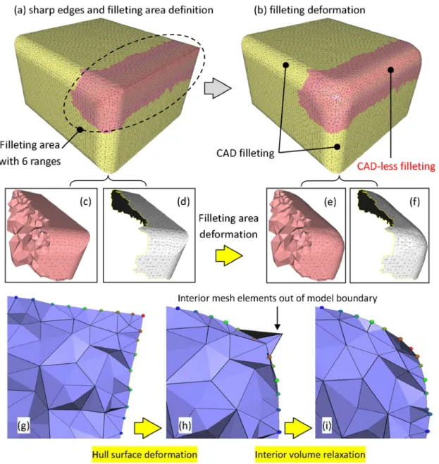
Figure 7 illustrates various steps of the CAD-less filleting experimentation performed on the partially rounded parallelepiped of figure 5. This example
SHARP EDGE FILLETING OF ENRICHED FE MESHES
9
presents fillets obtained with our mesh deformation tool and with a CAD system. It clearly shows that our results are well comparable with those obtained using traditional CAD tools. Figure 7.a shows the filleting area defined with 6 ring range neighbour-hood nodes around the sharp edges. Figure 7.b pre-sents the result of the 3D filleting. Figures 7.c and 7.d show the volume and the surface mesh part iden-tified by filleting operator and their deformed ver-sions are shown in figures 7.e and 7.f. The two de-formations applied to surface and volume mesh of the filleting area are illustrated in the figures 7.g, 7.h and 7.i. In this specific example, it is evident the ne-cessity of the second deformation step not only for guarantee the good quality of the meshes but also for avoiding self-intersecting configurations. The inter-mediate deformation on the model skin moves the boundary nodes onto a smooth shape whereas some internal mesh elements (tetrahedra) intersect the skin of the model (fig.7.j).
5. EXPERIMENTATIONS ON ACADEMY
AND INDUSTRY EXAMPLES
The first presented CAD-less filleting experimenta-tion is applied on a tetrahedral mesh on which a dis-continuity of the surface appears. The objective is to smooth this discontinuous area. Figure 8.a shows the
model on which the sharp edges representing the dis-continuity are identified. Figure 8.b shows the fillet-ing area defined by 3 neighbour ranges around the sharp edges. The resulting fillet is shown in figure 8.c. Here again, the deformation process consists in two stages. The first stage deforms the boundary sur-face of the filleting area in order to get a round shape from the shape feature depicted in figure 8.d. Figure 8.e illustrates the result of the first deformation that moves the boundary surface nodes of the filleting area onto a round shape in order to smooth the shape. Only moving the nodes on the boundary surface pro-duces stretched tetrahedra (fig.8.e). Then the second deformation relaxes the tetrahedra within the filleting area (fig.8.f).
The second CAD-less filleting experimentation con-cerns the hook tetrahedral mesh shown in the intro-duction (fig.1). The sharp edge to fillet is between the hook body and the handle part (fig.9.a). The fil-leting area is defined by 2 ranges of neighbour nodes surrounding the sharp edges (fig.9.b). The filleting deformation result is shown in the figure 9.c. The view of the internal mesh modified by the two stages deformation is given in the figures 9.d – 9.f. As in the previous examples the first deformation stage smoothes the model boundary surface (fig.9.e) and the second deformation stage (fig.9.f) relaxes the
terior mesh elements that were stretched during the first stage.
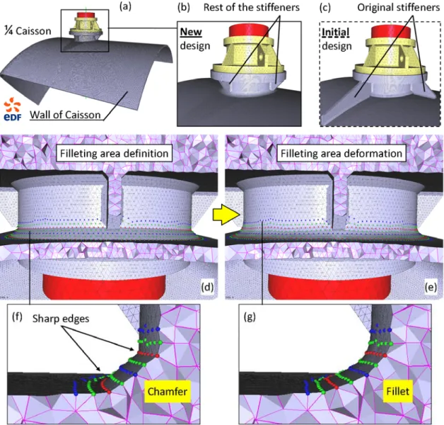
The third example (fig.10) consists in local filleting industrial FE mesh model (a quarter of Caisson in figure 10.a) provided by the EDF Group (Electricité de France). The aim here is to evaluate different local design solutions in order to guarantee the normal functioning of the caisson under given production conditions. One of design solutions to test is to cut away the stiffeners (fig.10.b) that were connecting the cylindrical part and the caisson wall on the initial model (fig.10.c) represented on the figure 10.b. In this design, the weld between the cylindrical part and the caisson wall is represented by a chamfer that has been used to simplify the welding modelling in the original model of the caisson (fig10.d and fig10.f). The choice of the design solution necessitates the analysing of mechanical stress in the structure under given exploitation loads. The assessment of the de-sign depends on the accurate evaluation of the stress concentration located at the weld joint. To improve the assessment of mechanical stress, we use the fillet-ing mesh deformation operator to smooth all sharp angles on the chamfer corresponding to a geometrical singularity. Smoothing of sharp angles allows reduc-ing the local stress. Figures 10.e and 10.g illustrate the fillet result performed by the mesh deformation operator.
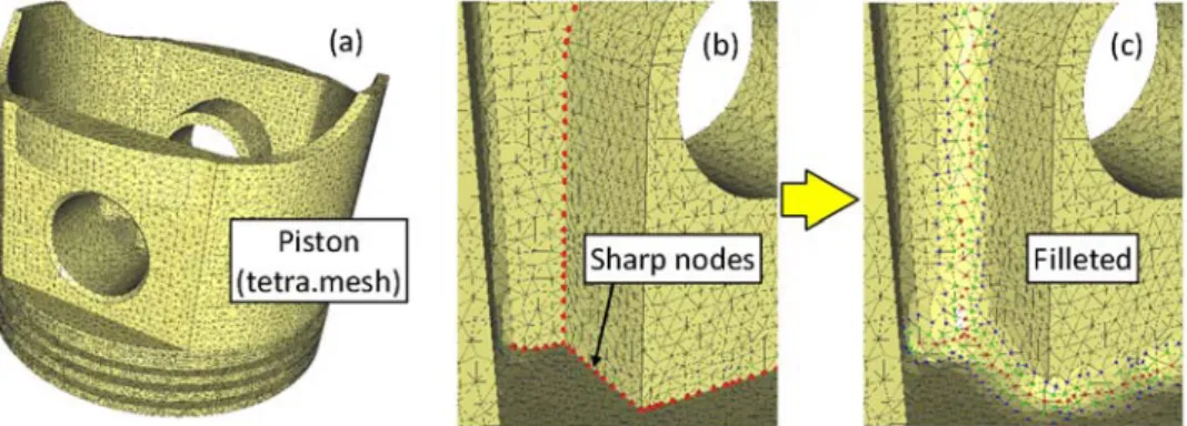
The last mesh filleting experimentation is performed on a tetrahedral mesh of an engine piston (Figure 11.a). The sharp nodes identified (fig.11.b) appear multi-branches. The filleting of two ranges nodes is shown in figure 11.c
6. CONCLUSION
This paper introduces a new CAD-less modelling framework together with a new instance of the ge-neric operator for the direct manipulation of enriched FE meshes. The proposed approach allows a much faster production and evaluation of solution alterna-tives than compared to current approaches, since it avoids time consuming loops of FEA model creation from CAD data needed for each change to validate. Such a possibility allows the experts to verify many more solutions and thus to achieve the best one. Even in the cases when the CAD model of the final solu-tion is needed, the approach is worth since it permits to perform the complete loop only for the chosen so-lution, instead of several.
The presented filleting operator works on both sur-face and volume FE meshes. To allow the re-use of the semantic information already associated to the FE mesh, the operator offers the advantage that solely the nodes located in the filleting area are reposi-tioned: the external onto a smooth surface, while (for
SHARP EDGE FILLETING OF ENRICHED FE MESHES
11
volume meshes) the internal tetrahedra are relaxed to guarantee an acceptable quality of the model.
Future work will concern the improvement of the treatment of the semantic information and of fillet shape specification. The full transfer of the semantic information associated to the filleting area has to be finalised, in fact the solution applied for the semantic transfer of operators involving the addition or re-moval of mesh elements cannot be directly applied in the case of fillet which simply involves node reposi-tioning. In addition, the solution should consider the nature of the associated semantics.
Concerning the geometrical aspect, the filleting area will be computed directly from the round radius im-posed by user. Along the sharp edges the number of ranges for defining the fillet area should be varied according to the density of the mesh elements.
More-over, capabilities for automatically performing mesh enrichment to achieve the desired shape according to the specified value of the fillet radius value. Con-cretely the tolerance between the perfect round sur-face and the filleted mesh sursur-face should be com-puted. If the tolerance is not acceptable, a mesh re-finement in the filleting area should be applied before the deformation
Moreover, support for overcoming problems due to noisy meshes in the sharp edges computations will be undertaken. For example, on a noisy mesh it can be possible that it is not possible to automatically detect a connected chain of the sharp edges as the user ex-pects. We can call this configuration a “hole” in the sharp edges. The system may assist the user in “fill-ing” the “hole” in the sharp edges chain.
REFERENCES
[1] Premysl Krsek, (2002), “Complex human tissues fem models prepared by Boolean operations”, Biome-chanics of man, Faculty of Physical Education and Sport Charles University in Prague, pp. 24-26. [2] D. Bremberg and G. Dhondt, (2008), “Automatic
crack-insertion for arbitrary crack growth”, Engineer-ing Fracture Mechanics, Vol. 75, Issue 3-4, pp. 404-416.
[3] H. Biermann, D. Kristjansson and D. Zorin, (2001), “Approximate boolean operations on free-form sol-ids”, Proc. of the 28th annual conference on Com-puter graphics and interactive techniques, SIG-GRAPH '01, pp. 185-194.
[4] W. Jung, Hayong Shin and Byoung K. Choi, (2004), “Self-intersection removal in triangular mesh offset-ting”, Computer-Aided Design and Applications, Vol. 1, New York, USA, pp. 477-484.
[5] M. Dakowicz and C. Gold, (2005), “Interactive tin modification with a cutting tool”, Proc. of 4th ISPRS Workshop on Dynamic and Multi-dimensional GIS, Pontypridd, Wales, UK, pp. 5-9.
[6] G. Turini, F. Ganovelli, and C. Montani, (2006), “Simulating drilling on tetrahedral meshes”, Proc. of Eurographics Conference, pp. 127-131.
[7] R. Chouadria and P. Veron, (2006), “Identifying and re-meshing contact interfaces in a polyhedral assem-bly for digital mock-up”, J. of Engineering with Computer, Springer-Verlag London, UK, Vol. 22, Is-sue 1, pp. 47-58.
[8] S.J. Kim, D.Y. Lee, and M.Y. Yang, (2004), “Offset triangular mesh using the multiple normal vectors of a vertex”, Computer-Aided Design and Applications, Vol. 1, No. 1-4, pp. 285-292.
[9] Sang Hun Lee, Won Kyung Lee and Kang-Soo Lee, (2001), "Rounding Operations on Shell Meshes for Efficient Analysis of Stamping Tools for Automotive Body Panels”, Proc. of the 11th Int. Pacific
Confer-ence on Automotive Engineering, Shanghai, China, IPC2001D067.
[10] Y. Liu, H. Zhang, J. Yong, P. Yu, and J. Sun, (2005), "Mesh blending", The Visual Computer, pp.915-927.
[11] R. Lou, A. Mikchevitch, J.-P. Pernot and P. Véron, (2010), “Merging enriched Finite Element triangle meshes for fast prototyping of alternate solutions in the context of industrial maintenance”, Int. J. CAD, Vol. 42, Issue 8, pp. 670-681.
[12] R. Lou, F. Giannini, J.-P. Pernot, A. Mikchevitch, P. Véron, B. Falcidieno and R. Marc, (2010), "Direct modification of semantically-enriched Finite Element Meshes", Int. J. IJSM, Vol. 16, Issues 1-2, pp. 81-108.
[13] R. Lou, F. Giannini, J.-P. Pernot, A. Mikchevitch, P. Véron, B. Falcidieno and R. Marc, (2009), "Towards CAD-less Finite Element analysis using group boundaries for enriched meshes manipulation", Proc. of ASME 2009 IDETC & CIE, Vol.2 San Diego, USA, pp.29-38.
[14] M. Attene, B. Falcidieno and M. Spagnuolo, (2006), "Hierarchical mesh segmentation based on fitting primitives", J. Visual Computer, Vol. 22, Issue 3, pp.181-193.
[15] D. Lesage, J-C Léon and P. Véron, (2005), “Discrete Curvature Approximations and Segmentation of Polyhedral Surface”, Int. J. IJSM, Vol. 11, Issue 2, pp. 217-252.
[16] T. Gatzke and C. Grimm, (2006), Estimating Curva-ture on Triangular Meshes, Int. J. IJSM, Vol.12, Is-sue 1, pp.1-29
[17] Z. Mao, G. Cao, Y. Ma and L. Kunwoo, (2011), Curvature estimation for meshes based on vertex normal triangles, J. Computer-Aided Design, Vol. 43, Issue 12, pp. 1561-1566.
[18] J-P. Pernot, G. Moraru and P. Véron, (2006), “Filling holes in meshes using a mechanical model to simu-late the curvature variation minimization”, Com-puters & Graphics, Vol. 30, Issue 6, pp. 892-902.