Science Arts & Métiers (SAM)
is an open access repository that collects the work of Arts et Métiers Institute of Technology researchers and makes it freely available over the web where possible.
This is an author-deposited version published in: https://sam.ensam.eu Handle ID: .http://hdl.handle.net/10985/18698
To cite this version :
Andrzej GALESKI, G REGNIER - Nano- and Micromechanics of Crystalline Polymers - 2009
Any correspondence concerning this service should be sent to the repository Administrator : archiveouverte@ensam.eu
Nano- and micromechanics of crystalline polymers
Andrzej Galeski*#, Gilles Regnier#
*Centre of Molecular and Macromolecular Studies, Polish Academy of Sciences, Sienkiewicza 112, 90363 Lodz, Poland
#Arts et Métiers ParisTech, Laboratoire d’Ingénierie des Matériaux-LIM, 151 bld de l’Hopital, 75013 Paris, France
1. Introduction
It is currently thought that crystalline polymers consists of lamellar crystals which are separated from each other by a layer of amorphous polymer and are held together by tie molecules through the amorphous phase [e.g. 1]. The lamellae are formed from mostly folded chains. The thickness of lamellae is determined by the parameters such as interfacial energies, glass transition temperature and melting temperature, undercooling, segmental diffusivity, etc. The thickness reported lies usually in a narrow range between 3 and 20 nm as obtained from observations in various types of microscopes or calculated from the degree of crystallinity and long period. It has been recognized that chain folding is not so regular as it was thought and molecular packing in lamellae is subject to considerable and irregularly distributed disorder depending on undercooling- regimes of crystallization. It has been demonstrated in various ways that the planar growth front will always break up into fibrous or cellular growth. Also crystallization of polymers leads to interface instability. More sophisticated treatment of the instabilities involve perturbation analyses of planar interfaces, correlating diffusion,
temperature gradients along the interface, and interfacial energy with the size of the growing crystals. All approaches show that all planar interfaces will develop and will yield fibrous or ribbonlike crystals [2 - 6]. When the crystals get larger they become stable and originate the growth of spherulites. The arrangement of lamellae within the spherulite can be best described based on the example of polyamide 6 spherulites [7]. The lamellae in bulk polyamide 6 are very long, flat and narrow. One can easily distinguish bundles of lamellae having similar orientation of flat faces and forming separate domains. Three to four lamellae form a small domain having similar orientation. As the spherulite is growing new lamellae are originated to fill the volume. New lamellae are added either to existing domain or originate new domain. The amorphous material is incorporated evenly between lamellae in the amount
corresponding to overall crystallinity. Misfit between domains arising from their different shapes are filled with amorphous material. Occasionally the lamellae may terminate; usually, however, once nucleated they continue to grow until impingement with neighboring
spherulites. New lamellae are formed mostly by non-crystallographic branching, by “giant” crystallographic dislocations and/or by crystallographic branching like in the case of isotactic polypropylene. In a number of polymers the stacks of lamellae are twisted to form banded spherulites.
2. Tensile deformation of crystalline polymers.
The mechanisms of tensile deformation of semicrystalline polymers were subject of intensive studies in the past [8-20]. It is believed that initially tensile deformation includes straining of molecular chains in the interlamellar amorphous phase which is accompanied by lamellae separation, rotation of lamellar stacks and interlamellar shear. At the yield an intensive chains slip in crystals is observed leading shortly to fragmentation but not always to disintegration of lamellae. Fragmentation of lamellae proceeds with deformation and the formation of fibrils is observed for large strains [21- 24].
In many papers concerning tensile deformation it was noticed that shortly after yielding some cavities are formed in a polymer [11, 12, 25-27]. The cavitation is not always observed in tensile tests, i.e. the process depends on the material and testing conditions and is never observed in compression of the same material [9]. It was shown in the past that a lamellae fragmentation and cavitation during tensile drawing are often detected simultaneously [21, 28, 29], however, it was never proved whether the lamellae fragmentation causes cavitation or vice versa. Since the cavitation appears around yield (at 4-12% of strain) while lamellae fragmentation in tensile drawing occurs at the strain of 30-40% [30] these two phenomena cannot be related directly. It seems more probable that the lamellae fragmentation is triggered by cavitaties when they reach a certain critical size. The lamellae fragmentation causes a release of 3D-stress, hence, limiting the possibility of further cavitation after fragmentation of lamellae.
3. Cavitation in tensile deformation
In the past the cavitation process was treated in literature as a marginal effect, however, recent studies showed that it may play an important role in the mechanism of plastic deformation [9,10, 17].
Usually the cavitation is detected by a small angle X-ray scattering (SAXS), seen as a rapid increase of scattering intensity. Macroscopically the intensive voiding is also observed as whitening of a deformed material.
Liu et.al. [13]noticed that the whitening of PP during tensile deformation was present in specimens drawn more quickly and at lower temperatures, i.e. when the yield stress was higher. The stress-whitening in tensile samples of polyolefins did not occur when the test is conducted under high pressure [14, 15]. Yamaguchi and Nitta [ 16] investigated the intensity of light transmittance while deforming polypropylene. They concluded that the
stress-whitening is observed just beyond the yield point, however, a decrease of transmittance begun at a strain of 0.07, i.e. before yielding at strain of 0.15.
Zhang et al. [12] analysed mechanisms of deformation for polypropylene differently irradiated, tested at selected temperatures. Authors concentrated mostly on polymer
microdeformation but evidenced the voids presence in most of samples. They observed that non irradiated polymer cavitates shortly after the yield, when the temperature was below 60oC. The SAXS scattering patterns indicate that the cavities change their shape during drawing from initially a peanut shell like to lemon like. Zhang et al. [12]proposed two explanations of shape change: a combination of scattering from primary cavities and a
scattering from the voids formed during fibrillation, or primary cavities are elongated to form the voids usually associated with fibrillation.
Some authors observed in drawn polypropylene a presence of craze-like features [31-35]. Crazing was identified long time ago in many glassy polymers, such as polystyrene. Crazes have a shape of planar cracks perpendicular to local strain direction[36-38]. The edges of a crack are bridged by highly oriented polymer fibrils, usually called tufts. They are parallel to the strain direction and are able to carry the load. The thickness of crazes is in the nanometer range, similarly as the thickness of fibrils. Crazes and fibrils can be detected by small angle X-ray scattering due to nanometer range of their sizes. The characteristic SAXS pattern consists of two components originating from voids and from fibrils, in a form of two
perpendicular streaks[36]. One of those streaks, very intense originating from planar crazes, is normal to craze planes while the second, usually less intense, is perpendicular to craze fibrils[36-37].
Crazing is a massive phenomena involved in plastic deformation of glassy polymers.
The features of craze-like structures observed in tensile drawing of PP at temperatures higher than the glass transition temperature are significantly different. First, their thickness is larger, in the range of 1-5 μm. Fibrils inside crazes, 200-650 nm thick[31], are elongated in the deformation direction, however, a significant fraction of thinner fibrils (20-50 nm) deviate from the principal strain direction[33]. Jang et.al. [33]showed that at 23 oC crazing is observed for strain rates higher than 0.11 s-2. Below this limit the deformation mechanism is
the shear yielding[33]. Henning et.al [34]by microscopic observations identified positions of intense crazing in deformed spherulitic structure. The conclusion was that craze-like features are visible for α- polypropylene in polar regions of spherulites. Some large scale, trans-spherulitic crazes were observed by Narisawa et.al. [35]passing through equatorial parts of spherulites.
Friedrich [31]and later Kausch[32] reviewed crazing processes in semicrystalline polymers. In their opinion it involves several stages: the initial stage is generally a macroscopically homogeneous deformation involving lamellar tilt and some breakup. At this stage the strain is accommodated almost entirely by the interlamellar amorphous regions[31]. Disruption of lamellae into 10-30 nm size blocks , voiding (with a length of voids from 10 to 50 and their thickness from 2 to 6 nm) and formation of fibrils between voids from partly extended tie molecules and crystal blocks characterize the intermediate stage. The third stage, at higher draw ratios, leads to a perfect stretching of the fibrils. The fibrils, spanning the edges of a craze and possessing the strength of about 1 to 2 orders higher than the yield stress, are able to stabilize the microvoid volume. A lateral coalescence of these voids finally provides a local deformation zone in the shape of a craze. Friedrich limited this description to a low
temperature crazing. The Kausch description[32] differs from Friedrich envision in that that in the first stage the interlamellar separation of lamellae oriented perpendicularly to
deformation direction is followed by cavitation and/or crystal plastic deformation and not lamellar fragmentation. Lamellar fragmentation occurs at the intermediate stage.
In an earlier paper by Galeski, Argon and Cohen [39] the following scenario of crystalline polymer deformation under the imposed uniaxial tension was outlined: the packets of lamellae in the 45o fans of spherulites experience resolved shear stress that promote chain slip in the lamellae and shear in interlamellar amorphous regions (see Figure 1).
Figure 1. Tensile deformation of a spherulite. Lamellae kinking and formation of cavities in equatorial zones of a spherulite are formed. Lamellae fragmentation occurs in polar fans of spherulites, potential cavities may be also expected . Redrawn after [39].
Such deformation is accompanied by lattice rotation which generates tensile stresses across the faces in equatorial plates and compressive stresses across the faces in polar fans of
spherulites. In addition to these, the overall elongation of spherulites evokes radial pressure on the equatorial planes and additional tensile stresses in the radial direction on the polar fans. Since these accentuated stresses in equatorial lamellae packets have no important shear components either on the interlamellar layers or on the planes of lamellae that promote chain slip, other more damaging types of local plastic deformation are enforced. As is well known [40] compression of such composite stacks lamellae and amorphous layers along stiff
lamellae gives rise to unstable kinking of the lamellae. This produces periodic undulations in the lamellae ribbons. The accentuated tensile stresses acting across the equatorial disks of a spherulite expand amorphous material within lamellae kinks into pores. A similar and complementary processes are expected to occur in a polar fans of spherulites, however, no action is expected from the amorphous phase, but instead, from the lamellae ribbons. In this case the chain fold planes in the lamellae form an unstable stacks in tension. Any
inhomogeneous lamellae kinks would be filled with amorphous material under transverse pressure, producing no voids. Thus, the end result should be the array of aligned cavities in the equatorial disks of spherulites.
The above outlined picture of voiding in crystalline polymers above Tg differs significantly from craze formation in glassy amorphous polymers:
1. Formation of aligned voids is triggered by compressive kinking instability along lamellae in equatorial disks of spherulites and not by meniscus instability as in the case of crazes in glassy amorphous polymers. Distances between voids are
characteristic for kinking that is dependent on several factors, the most important being the lamellae thickness[41]. The wavelength of kinks in crystalline polymers is usually of order of 200-500 nanometers. The voids are narrow and long as the width of kinked fragments of lamellae.
2. Growth of craze-like entities in equatorial disks of spherulites occurs via plastic deformation of the amorphous material between laterally aligned voids that is transformed further into fibrils. The thickness and length of these fibrils is related to the amount of the amorphous material between voids and that is connected in the first
approximation with the lamellae thickness. These fibrils may mimic tufts in crazes of amorphous glassy polymers.
3. Voids in other parts of a spherulite arise at later stages of deformation and the
mechanisms of their formation is different. Since there are no dilatational stresses at 45o fans of spherulites the interlamellar slip and chain slips in lamellae prevails and no voiding is usually observed.
4. A disruption of lamellae in polar fans of spherulites is required, pores are formed at larger overall strain when the amorphous material becomes unable to fill significantly increased gaps between lamellae fragments. At even further strain the neighbouring voids coalesce in planes perpendicular to drawing direction while the amorphous material between these voids is transformed into fibrils. The thickness of those fibrils is related to the thickness of the amorphous layers and depends on the strain at which the voids coalesce and fibrils are formed. These craze-like entities resemble rather thick cracks because fibrils usually break at such high local strain.
The above concept of formation of craze-like objects in crystalline polymers explains the existence of bimodal distribution of fibril thickness and is also supported by recently published AFM studies for initiation of voids in polybutene spherulites and their transformation into craze-like entities with increasing deformation[42]. The craze-like
features in polypropylene are seen by electron microscopy, however, in contrast to crazing in glassy amorphous polymers, the fibrils in PP are usually not detectable in SAXS experiments probably due to a small number of fibrils and their large thickness.
Some SEM observations (e.g. Jang, B.Z et.al.[33]) show fibrils in drawn PP only after etching. However, it is not clear whether these are craze tufts or remnants of initial cross-hatched PP lamellae revealed by etching. The last case seems more reasonable because there are two populations of fibrils, the second one is nearly perpendicular to the first one just as in cross-hatched morphology.
In some other papers (e.g. [19]) the term “crazing” is misused for the description of microcracks.
Formation and growth of cavities are the main reasons of volume change during tensile drawing. The concept of volume strain, introduced by Bucknall[43], was recently applied for the studies of semicrystalline polymers [44-48] . The volume strain of cavitating polymers may significantly increase with increasing draw ratio, and reach 0.4 for PET [45] and more than 0.15 for PVDF [46]. Recently, Billon et.al. [49] observed a rapid increase of volume
strain for PP, resulting from nucleation of voids in the core of injection molded polypropylene samples.
It was shown that for most of crystalline polymers including polypropylene and other polyolefins the tensile drawing proceeds at a much lower stress than kinematically similar channel die compression [10, 17]. Lower stress in tension was always associated with cavitation of the material. Usually a cavitating polymer is characterized by larger and more perfect lamellar crystals and cavities are formed in the amorphous phase before plastic yielding of crystals. If the lamellar crystals are thin and defected then the critical shear stress for crystal plastic deformation is resolved at a stress lower than the stress needed for
cavitation. Then voiding is not activated. An example of such behavior is low density polyethylene [10].
4. Tensile deformation of polyethylene and polypropylene.
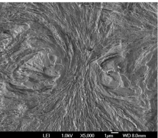
Recently the cavitation during tensile deformation in high density polyethylene was studied in details [50]. The samples were prepared by both injection and compression moldings in order to differentiate their internal structure and perfection of lamellae. It was shown that cavitation in HDPE depends on lamellae thickness and their arrangement. For example, when the crystals were oriented perpendicularly to drawing direction, as in the skin of injection molded specimen, the cavities were formed readily as early as at 1% of elongation
Figure 2. The evolution of SAXS scattering pattern with the increase of stress applied to the HDPE-I. Deformation direction was horizontal. Redrawn after [50].
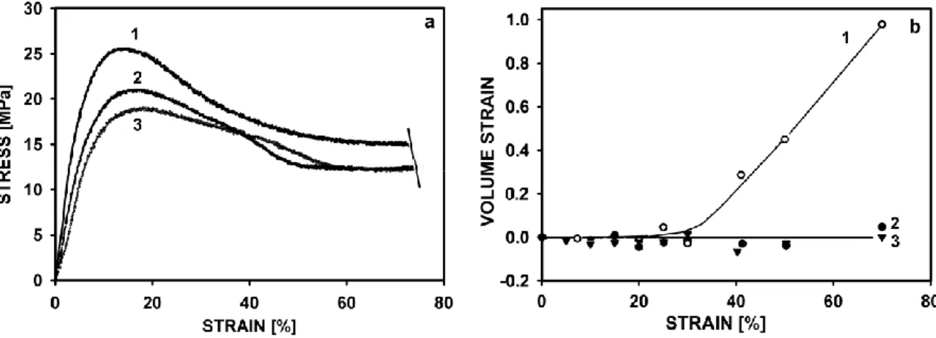
Cavitation in the core of the same injection molded HDPE sample was observed at yield (above 10% of elongation). The shape of cavities changes with increasing deformation similarly as it was described by Zhang et.al. [12]. It was also shown that the same polymer formed by rapid cooling of melt is able to deform without cavitation during tensile drawing. The stress-strain curves for compression molded HDPE cooled in air, in water and in iced water together with respective volume strain measurements are presented in Figures 3a and 3b.
Fig 3. a) Stress-strain curves for compression molded HDPE samples, deformed to 75% of engineering strain. Different cooling procedure was applied during preparation: 1- sample cooled in the air, 2- sample cooled in the water, 3- sample cooled in the water with ice. Redrawn after [50].
Polypropylene is a cavitating polymer similar to polyethylene, but the process of cavitation proceed differently. The role of molecular weight, crystal thickness and testing rate on the formation of cavities and their growth during tensile deformation were the subjects of detailed studies [51]. The injected samples of PPH and PPN deforms plastically with necking and significant increase of the volume is observed only after the yield. The increase of volume is accompanied by intensive whitening of samples. The reason of whitening and volume increase is cavitation initiated in the amorphous phase, which was confirmed by SAXS studies. The volume strain is larger for lower molecular weight PP polymer, in which the amorphous phase is less entangled. Apparently a lower number of entanglements supports easier and more numerous cavitation. The cavities are formed during tensile drawing in the center of injected PP samples shortly before yielding. At small local strains, after the yield, a partial healing of small cavities is possible. The zone of cavitation propagates to the rest of sample with increasing deformation. In the skin of injected samples voids are not detected for lower local strains than 2.6 in contrast to the core injection molded bars of PP of lower and also higher molecular weight. That is because in the skin the crystalline structure is less developed which leads to crystallographic non-cavitational mechanism of deformation. Cavitation process occurs when the crystals are enough perfect and strong, i.e. when the stress for plastic deformation of crystals is higher than the stress needed for cavitation of the
amorphous phase. At low local strain the cavities are elongated perpendicularly to
deformation direction. Typical radius of gyration for voids, as obtained from SAXS analysis, in PP of higher molecular weight is 18 nm and 12nm for voids in PP of lower molecular
weight. If we assume ellipsoidal shape of voids and that their thickness is equal to the
amorphous layer thickness (approximately 7 nm) then the lateral size of cavities is around 80 nm in PP of higher molecular weight and around 50 nm in PP of lower molecular weight. The cavities grow with increasing strain and also some new voids are formed.
The volume strain does not increase continuously with deformation. There is a plateau in volume strain for applied local strains between 1.0 and 4.0, where the change of internal crystalline structure - orientation and fragmentation of lamellae- leads to a change of voids shape from elongated perpendicular to elongated in the deformation direction. Reorientation process sets in for local strains of 0.8-1.0
The structure of compression molded samples is more uniform than the injection molded bars, so the cavitation occurs across the gauge of the sample. The presence of cavitation in those samples depends on the strain rate. If the deformation is slow then the crystalline elements are able to deform plastically before reaching the cavitation threshold of amorphous phase. When the strain rate is higher the yield stress, related to crystal strength, is higher (38-38.5 MPa) and cavitation occurs first.
The lack of fibrils bridging the walls of cavities results from the mechanism of their formation within spherulitic structure in crystalline polymers above their Tg as explained in above[39]. Drawing below Tg may produce craze-like features because inhomogeneous lamellae kinks would not be easily filled with glassy amorphous material under transverse pressure, producing voids and drawing crazy tufts in polar fans of spherulites.
The main reasons of cavitation are the misfit between mechanical compliances of heterogeneous element and the surrounding and the resulting excessive negative pressure. Cavitation appears to be another mechanism of tough response of the material [e.g 52, 55]. Although the cavitation dissipates not very large amount of energy, it enables the surrounding material to undergo further intensive crazing or shear. The possibility of cavitation under external force strongly depends on the character of applied deformation and is larger under tension than under compression. Cavitation in macro scale is visible as whitening. The
voiding was observed in many drawn polymeric materials such as polypropylene [54-57] and high density polyethylene [58], but not in some others like ethylene--olefin copolymer [59,60]. It was established in the past that a low crystallinity level and a fine spherulitic structure are advantageous for development of crazes in semicrystalline polymers[61]. Unlike in amorphous polymers crazing in semicrystalline polymers is not restricted to temperatures below Tg but occurs also above the glass transition of the amorphous phase[62]. Below Tg long crazes propagate perpendicularly to load direction ignoring internal polymer structure
while at a temperature close to Tg crazes are confined to several spherulites[31, 62, 63]. Radicals formed due to macromolecules chain scission were observed in oriented polymers during tensile deformation[64, 65].
The internal cavitation observed in tension experiments has been referred to as "micro necking" by Peterlin[66]. It was supposed that "micro necking" removes kinematical constraints between lamellae and allow them to untangle. However, from this picture as imagined by Peterlin, it follows that the drawing of crystalline polymers inherently involves cavitation as an essential feature. While the above picture is reasonable in tensile deformation, it is not correct for modes of deformation not producing cavitation, in which positive normal stress component prevents for the formation of cavities. "Micro necking" is inessential for the development of nearly perfect single crystal textures, as it was shown for several semi
crystalline polymers that result from the deformation modes involving positive pressure component[67-72]. One of the possibilities of cavity free deformation is plane strain
compression in a channel die[73]. Plane strain compression in a channel die is kinematically very similar to drawing: the sample is extended and its cross-section decreases accordingly. However, no neck is formed and the possibility of voids formation is limited due to a compressive component of stress. It is reasonable to expect that similar elementary plastic deformation mechanisms are initiated under similar true stress in tension and in plane strain compression. It means that any differences in true stress- true strain dependences of drawn and plane strained materials should be attributed to the formation and development of cavities. The number of observations of polymer deformation behavior under positive pressure at the level preventing for cavitation which can be found in literature[e.g. 14] is limited and no comparison with tensile drawing was made. It is known that the stress in heterogeneous systems is not homogeneously distributed. At sites with a misfit of mechanical properties the stress concentrates, its value may increase locally many folds and trigger cavitation. In the case of crystalline polymers such sites are between differently oriented packets of lamellae and the stress concentration factor can reach 3 or more.
In the paper by Galeski, Argon and Cohen[39] the imprints of cavitation were revealed by osmium tetroxide staining in drawn polyamide 6. The cavitation occurred in the amorphous layers confined by the crystalline lamellae. In fact the cavities left the traces of damaged material having the size of order of the interlamellar distance, i.e. 4-5 nm. Since cavitational voids are having sizes on the nano-scale level, there is a problem of their stability. On each nanopore the surface tension is exerted from the very beginning of their formation,
which tends to close a pore. In order to preserve a pore an action of a negative pressure is required at the level which is reciprocally proportional to the radius of a pore:
p = -2s/r (1)
where s is the surface tension and r is the size of a pore. It follows then that the smallest pores are healed readily while larger pores can be preserved only if the negative pressure is maintained at a sufficiently high level. The lack of negative pressure or its inadequate level will lead to a spontaneous healing of cavitational pores; otherwise they can grow in the course of drawing.
In the papers by Muratoglu et al. [74, 75] it was shown that when cavitational pores arise they form initially a spherical voids which later grow and become elongated. It is then logical to suppose that at the moment of cavity formation the stress concentrates around a spherical inhomogeneity and, as it was calculated earlier by Goodier [76] for spherical inclusions, isincreased by a factor of 2. Also the negative pressure generated is increased accordingly.
Table I. Surface tensions [77-79] and negative pressures involved in cavitation during drawing. Polymer Surface tension [mJ/m2] Amorphous layer thickness * [nm] Negative pressure needed to maintain cavity open [MPa] Tensile yield stress [MPa] Negative pressure generated at yield around newly formed cavities [MPa] POM 44.6 4.69 -35.8 63 -42.0 PA6 38.4 5.59 -33.6 42 -28.0 PP 29.4 8.16 -13.7 31 -20.7 HDPE 35.7 9.45 -15.1 23 -15.3 LDPEs 35.3 7.50 -17.6 7 - 4.7
*calculated on the basis of SAXS long period and DSC degree of crystallinity.
In Table I the data on surface tension, thickness of the amorphous layers, negative pressure needed to maintain the cavity open (according to equation (1) assuming the radius of newly formed cavity equal to half of the amorphous layer thickness) and the yield stress in drawing are presented. In the last column of the Table I the negative pressure generated at yield around newly formed cavities is listed. These values of pressure result from the stress at yield ( -
yield/3) increased by a factor of 2 arising from the stress concentration as predicted by Goodier [76].
It is clearly seen that the negative pressure at concentration sites, which is the negative pressure at yield (- yield/3) multiplied by stress concentration factor 3, can cause cavitation in the case of PA 6, POM, PP and HDPE because it is higher than the negative pressure for cavitation in polymer melts (HDPE from -3.5 to -10 MPa[80], PP from –13 to -19 MPa [ 81-83], POM from –10 to -18MPa [81-83] but not adequate for cavitation of LDPEs.
In POM, PP and HDPE the yield stress generates sufficient negative pressure around cavities to maintain them and to boost their further growth. In fact the cavitation in those polymers during drawing is evidenced by density decrease and strong small angle x-ray scattering.However, it is also evident that the negative pressure generated around newly formed cavities is not sufficient to keep them open in the case of PA 6; the cavities in PA 6 are unstable and will heal quickly. Really, the transmission electron microscopy (TEM) examination [39] of the same material does not expose any empty voids but only traces of chemically changed material between crystalline lamellae. It must be mentioned here that the growth of cavities proceeds in fact due to the deformation of the surrounding matter,
therefore, it is due to the action of dilatational stresses and not due to negative pressure.
5. Deformation micromechanisms in crystalline polymers..
There are three, currently recognized, principal modes of deformation of the amorphous material in semicrystalline polymers: interlamellar slip, interlamellar separation and lamellae stack rotation [84, 85]. Interlamellar slip involves shear of the lamellae parallel to each other with the amorphous phase undergoing shear. It is a relatively easy mechanism of deformation for the material above Tg. The elastic part of the deformation can be almost entirely attributed to the reversible interlamellar slip.
Interlamellar separation is induced by a component of tension or compression perpendicular to the lamellar surface. This type of deformation is difficult since a change in the lamellae separation should be accompanied by a transverse contraction and the deformation must involve a change in volume. Hard elastic fibers are found to deform in such way. When the lamellae are arranged in the form of stacks embedded in the amorphous matrix then the stacks are free to rotate under the stress. Any other deformation of the amorphous phase requires a change in the crystalline lamellae; the amorphous material is then carried along with the deforming crystalline material.
Many authors identified two distinct yield points in PE deformed in the tensile mode which are not seen in other deformation modes not producing cavitation. Gaucher-Miri and Seguela [86] tried to clear up the mechanism of this two processes on the micro-structural level, as a function of the temperature and strain rate.
The major contribution to toughness comes from plastic deformation of the material which is manifested by the ductile behaviour. Plastic deformation itself is a composed phenomena: it concerns the crystalline as well as amorphous phases. The ductility is
expressed by lowering of the stress-strain curve at a certain stress called the yield stress. Yield can be caused either by multiple crazes or by shear yielding. In the first case the crazes have to be initiated in a relatively large volume of the material in order to contribute significantly to the overall deformation. Shear yielding is the plastic flow without crazing. Crazing is an unique phenomena occurring in polymers below the glass transition temperature. Crazes themselves are highly localized zones of plastic dilatational deformation [e.g.87-90]. Edges of crazes are spanned by highly drawn elongated fibrils called tufts, usually having the length
of a fraction of 1 m depending on the molecular weight of a polymer, the diameter of several nanometers and confined to a small volume of the material. The tufts can carry the load applied to the material and preserve its integrity. In brittle materials crazes are initiated at surfaces. Brittle fracture is usually caused by microcracks originating from breaking crazes initiated from the surface. Crazing occurs mostly in amorphous polymers although it has been also observed in crystalline polymers in which crazes are propagated between lamellae
through spherulite centers as well as through the material between spherulites [91,92]. Localized crazes initiate, propagate and break down to give microcracks at the stress below that which is necessary to stimulate shear yielding
Shear yielding can be observed in a wide range of temperature but only if the critical shear stress for yielding is lower that the stress required to initiate and propagate crazes.
Ductile deformation requires an adequate flexibility of polymer chain segments in order to ensure plastic flow on the molecular level. It is long known that the macromolecular chain mobility is a crucial factor deciding on either brittle or ductile behavior of a polymer [93-95]. An increase in the yield stress of a polymer with a decrease of the temperature is caused by the decrease of macromolecular chain mobility, and vice versa, the yield stress can serve as a qualitative measure of macromolecular chain mobility. It was shown that the temperature and strain rate dependencies of the yield stress are described in terms of relaxation processes, similarly as in linear viscoelasticity. Also the kinetic elements taking
part in yielding and in viscoelastic response of a polymer are similar: segments of chains, part of crystallites, fragments of amorphous phase. However, in crystalline polymers above their glass transition temperature the yield stress is determined by the yield stress required for crystal deformation and not by the amorphous phase. The behavior of crystals differs from that of the amorphous phase because the possibilities of motion of macromolecular chains within the crystals are subjected to severe constraints. Since the mobility of kinetics elements taking part in a plastic deformation is lower at a lower temperature, the energy dissipated increases and produces instability; at those places micronecks are formed because locally the temperature increases. The rate of plastic deformation increases drastically in micronecks and the material may quickly fracture. At higher temperature the mobility of kinetics elements is higher so, less energy is dissipated and the local temperature increase is lower. As the result the neck is stable and tends to occupy the whole gauge length of the sample. The material exhibits then a tough behavior.
The necessary condition for high plastic deformation is the possibility of motions of kinetic elements in a time scale as it follows from the deformation rate. The relaxation times and the activation energies are the parameters describing the kinetics of the conformation motions of macromolecules and larger elements taking part in the deformation. In crystalline polymers there are essentially three processes which are of particular importance: the first process which is connected with the presence of crystalline phase, the second corresponding to relaxations related to defects in the crystalline phase and the third which corresponds to motions of short segments in the amorphous phase related to the glass transition[94] .
Both massive crazing and shear yielding dissipate energy, however, shear yielding is often favored over crazing, especially under uniaxial stress, elevated temperature or slow deformation. Shear yielding dissipates the energy more efficiently [94]. Switching between crazing and shear yielding is not obvious as it depends also on additional factors such as shape of an article and the presence of notches or scratches. If all other factors are equal the material will deform according to a most ductile mechanismwhich is well explained by the Ludwig-Davidenkov-Orovan hypothesis[96-98] explained inFigure 4.
Fig.4 Ludwig-Davidenkov-Orovan plot explaining the temperature dependence of ductility and brittleness of a material. Redrawn after Ward and Hadley [99].
The deformation of polymeric materials starts usually at scratches, notches or internal defects because these places are the zones of local stress concentration, sometimes much above the applied stress. Toughening of polymeric materials is based on the activation of such plastic deformation mechanisms which are activated at a stress lower than that required for triggering the action of surface and internal defects. Consequently, one of the important means of toughening appears to be a significant lowering of yield stress of a material [100].
6. Molecular mechanisms at a nanometer scale.
Taking into consideration the yield behavior of semicrystalline polymers there are two conflicting approaches concerning the crystals. The first presumes that the process of
deformation is composed of a simultaneous melting and recrystallization of polymer under adiabatic conditions [101,102].The second, developed mainly by Young [103] uses the idea derived from the classical theory of crystal plasticity. The deformation of polymer crystals is considered in terms of dislocation motion within the crystalline lamellae, similarly to slip processes observed in metals, ceramics and low molecular crystals. Crystallographic slips are not processes occurring simultaneously over the whole crystallographic plane. A great role of line and screw dislocations are played in activation and propagation of a slip. Recently the issue of melting-recrystallization vs.crystal plasticity was raised again by Seguela [104]. His conclusion is that melting-recrystallization may occur at high strain rates, during lamellae fragmentation and at high strain when collective chain unfolding takes place. However, most of published data concern the systems in which plastic deformation is accompanied by cavitation-the phenomena neglected by most of the authors. Also Seguela in his revoking
review [104] does not refer to the relation between lamellae fragmentation and cavitation. Recent papers of Strobl [30], Lv et al. [105] and Pawlak et al. [51] present the attempts to correlate the two coexisting phenomena.
The plastic deformation of polymer crystals, like the plastic deformation of crystals of other materials, is generally expected to be crystallographic in nature and to take place without destroying the crystalline order. The only exception to this is a very large
deformation, when cavitation and voiding lead to unravelling the folded chains and break down completely the crystals, new crystals may form with no specific crystallographic relationship with the original structure [106].Polymer crystals can deform plastically by crystallographic slip, by twinning and by martensitic transformation. The slip mechanism is the most important one since it can produce larger plastic strains than the other two
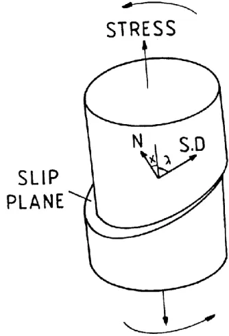
mechanisms. A slip system in a crystal is the combination of a slip direction and a slip plane containing that direction as shown in Figure 5.
The notation for the slip system is (hkl)[h1k1l1] where (hkl) is the slip plane while [h1k1l1] is the slip direction. A single slip system is only capable of producing a simple shear
deformation of a crystal. A general change of a shape of a crystal requires the existence of five independent slip systems [107]. Polymer crystals rarely possess this number of independent slip systems. However, under the right conditions the deformation of bulk material can occur without voiding or cracking perhaps because amorphous regions between lamellae allow for certain amount of adjustment. In polymer crystals the slip plane is
restricted to planes which contain chain direction. That is because covalent bonds remain unbroken during deformation. In polymers two types of slip can occur: chain slip i.e. slip along the chains and transverse slip i.e. the slip perpendicular to the chains both slips
occurring in planes containing the chains. The general rule that applies to slip deformation is that the plane of the easiest slip tends to be a close-packed plane in the structure and the slip direction is a close-packed direction. Hence, in crystalline material, it is possible to predict certain mechanical properties associated with crystallographic slip directly from the
crystallographic unit cell [108]. In folded chain polymer crystals the folds at the surface of crystals may in addition impose some restraint on the choice of a slip plane; usually a slip will be able to occur only parallel to the fold plane. An implication of the geometry of the slip process is that a crystal undergoing a single slip will rotate relative to the stress axis as it is seen in Figure 6.
Figure 6. The rotation of crystal fragments due to slip: marked by arrows. The resolving of the shear on a plane due to simple tension or compression is also illustrated.
For a single slip the slip direction in the crystal rotates always towards the direction of maximum extension: in uniaxial tension it rotates towards tensile axis while in uniaxial compression away from the compression axis. The angle through which the crystal rotates is a simple function of the applied strain[107]. It must be mentioned that the slip takes place when the resolved shear stress on the slip plane reaches a critical value known as a critical resolved shear stress. The critical resolved shear stresses for slips are now well known only for few polymers.
They were measured using samples of rather well defined texture. First measurements performed on polyethylene sample with fiber texture subjected to annealing at high pressure for increasing the crystal thickness yielded the critical shear stress of 11.2 MPa for
undisclosed crystal thickness [84].However, with fiber symmetry a combination of easiest slip systems could act simultaneously disturbing the true value of the critical shear stress. The most exact data concerning critical resolved shear stresses for possible slip systems in
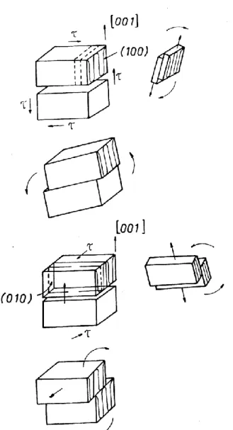
polyethylene were obtained by Bartczak et al.[109].They used single crystal textured polyethylene obtained by plane strain compression. The measurements in uniaxial tension, uniaxial compression and simple shear for samples cut out at various orientations delivered the following: for polyethylene orthorhombic crystals [109] the most active slip system is (100)[001] chain slip at 7.2 MPa, the second is (100)[010] transverse slip at 12.2 MPa, and the third is (010)[001] chain slip at 15.6 MPa. The forth slip system for polyethylene
orthorhombic crystals was predicted as (110)[001] with the estimated critical resolved shear stress greater than 13.0 MPa [109], however, it was never observed separately.
For polyamide 6 crystals the slip systems are: (001)[010] chain slip at 16.24 MPa, (100)[010] chain slip at 23.23 MPa and (001)[100] transverse slip [71]. Relatively little attention was paid to the plastic deformation of other semicrystalline polymers [98, 110]. In particular, there are only few papers [111, 112] describing the investigations of the yield behaviour and plastic resistance of oriented iPP.
For the determination of critical shear stress of one of the most important deformation mechanisms of iPP crystals, namely the crystallographic slip in the (100) planes along chain direction, i.e. (100)[001] chain slip[113, 114], the biaxially oriented film was used[115]. According to the theoretical predictions[ 113] and experimental studies [116] the easiest slip system in iPP crystals is (010)[001] slip, while (100)[001] and (110)[001] systems have higher critical resolved shear stress. The studies of the mentioned above slip system can be made by the investigation of the yield behaviour of the specimens deformed in tension with the tensile axis oriented in those specimens at various angles to the orientation direction. One can expect that for a certain range of this angle only the (100)[001] slip system will be activated due to proper orientation of crystallites providing high shear stress on the (100) plane in [001] direction, while other deformation mechanisms will remain inactive due to much smaller resolved shear stresses in appropriate directions [109,116].The analysis of the yield stress of such samples would give the value of the shear stress necessary to activate the (100)[001] slip[85, 109,110, 117]. The critical resolved shear stress for (100)[001] slip for crystals of polypropylene was determined at the level of 22.6 MPa. Similar studies for oriented iPP in tension and compression were performed by Shinozaki and Groves [111]but they used the samples of uniaxially oriented iPP with a fiber symmetry, so that the critical
shear stress they determined, 25MPa, was an average over slips in plane oriented around the fibre axis.
Crystal orientation by channel die compression of PET was studied by Bellare et al [117]. They have found that the macromolecular chains orientation in PET along the flow direction and the texture development are the results of possible crystallographic slips having the following glide planes and directions: (100)[001] chain slip and (100)[010] transverse slip and (010)[001] chain slip. Probable sequence of activities of these slips is the following: the (100)[001] chain slip being the easiest, (100)[010] slip and a sluggish (010)[001] chain slip [118]. Values for critical resolved shear stress for those slips were not determined.
The stress induced martensitic transformation is a transformation from one crystallographic form to another form and associated by a displacement of chains to new positions in the new crystallographic cell in order to accommodate the deformation. An example of martensitic transformation from orthorhombic to monoclinic form was found in oriented polyethylene with well defined texture subjected to uniaxial compression. The martensitic transformation was also found in other polymers: in poly(L-lactic acid) [119] and
in nylon 6 with the form transforming to the form [120, 121].
iPP highly rich in crystal modification (92%) were deformed by the plane-strain
compression with constant true strain rate, at room temperature[122]. The results allowed to find out the deformation sequence and the active deformation mechanisms. The most
important were interlamellar slip operating in the amorphous layers and resulting in
localization of deformation in numerous fine deformation bands and the crystallographic slip systems, including the (110)[001] chain slipand (110)[1-10] transverse slip. Deformation within deformation bands leads to smectic and solid state phase transformations. At room temperature the smectic transformation appeared the primary transformation and
transformation yields only about 4wt.% of new phase at the same strain. With numerous fine deformation bands lamellae are locally destroyed and fragmented into smaller crystals. Another deformation mechanisms is a cooperative kinking of lamellae, leading to their reorientation and formation in a chevron-like lamellar arrangement. At high strains, above true strain equal 1, an advanced crystallographic slip and high stretch of amorphous material due to interlamellar shear bring further heavy fragmentation of lamellar crystals partially fragmented earlier by deformation bands. This fragmentation is followed by fast rotation of small unconstrained crystallites with chain axis towards FD. This process leads to development of the final texture of the highly deformed -iPP with molecular axis of both crystalline and smectic phase oriented along the direction of flow. At higher
temperatures in the range 55-100°C the most important deformation mechanisms found were interlamellar slip operating in the amorphous layers, resulting again in numerous fine
deformation bands and the crystallographic slip systems, including the (110)[001]β chain slip and (110)[1-10]β transverse slip. Shear within deformation bands leads to β→α solid state
phase transformation in contrast to β-→smectic transformation observed at room temperature. Newly formed α crystallites deform with an advancing strain by crystallographic slip
mechanism, primarily the (010)[001]α chain slip. As a result of deformation and phase transformations within deformation bands β lamellae are locally destroyed and fragmented into smaller crystals. Deformation to high strains, above true strain equal 1, brings further heavy fragmentation of lamellae, followed by fast rotation of crystallites with chain axis towards the direction of flow FD. This process, together with still active crystallographic slip, leads to the final texture with molecular axis of both crystalline β and phase oriented along flow direction.
Another example of active martensitic transformation is modification of polypropylene. Morphology and deformation behavior of iPP homopolymer containing
exclusively modification with only minor traces of crystals, obtained by isothermal crystallization at high pressure of 200 MPa, were investigated by Lezak et al. [123]. Deformation experiments performed in the plane-strain and uniaxial compression,
demonstrated higher modulus, higher yield stress and flow stress, yet slightly lower ultimate strain of -iPP as compared to iPP. During plastic deformation numerous fine shear bands, initiated by the interlamellar shear of the amorphous layers start to develop already at the yield point. Their propagation across the sample causes a limited destruction of lamellae oriented perpendicularly to the direction of the band. Destroyed fragments of crystallites transform partially into smectic phase. No - phase transformation was detected. With increasing strain the shear bands multiply and tilt towards the flow direction. Lamellae, already fragmented within shear bands, undergo kinking and rotation, resulting in the formation of a chevron-like lamellar morphology. Simultaneously, a relatively weak one-component crystalline texture is developed. This texture is described by the orientation of c crystallographic axis along CD, b axis 10-30o away of LD towards FD and a axis 10-30o away from FD. Both crystalline texture and lamellae orientation are developed due to the activity of the same deformation mechanism - the interlamellar slip produced by the shear within interlamellar amorphous layers. Activity of any crystallographic deformation mechanism within crystalline component, including the anticipated (001)[010] transverse slip, was not
detected. The interlamellar amorphous shear appears the primary deformation mechanism of -iPP. The other identified mechanism, -smectic phase transformation, plays rather a minor, supplementary role in the deformation sequence. Plastic deformation behavior of iPP
homopolymer crystallized exclusively in the γ modification at higher temperature in the range 55-100°C was also studied by Lezak et al.[124]. During plastic deformation numerous fine shear bands, initiated by the interlamellar shear of the amorphous layers, start to develop already at the yield point. Their propagation across the sample causes a limited destruction of γ lamellae oriented perpendicularly to the direction of the band. Destroyed fragments of crystallites partially reconstruct into either mesophase (smectic) domains or crystals of α phase, depending on the deformation temperature. Mesophase is produced upon deformation at room temperature, while at 55°C and above the crystalline α phase is formed instead. With increasing strain shear bands multiply and tilt toward the flow direction. Fragmented lamellae undergo kinking and rotation, which results in the formation of a chevron-like lamellar morphology. This leads also to a development of a weak crystalline texture. Both crystalline texture and lamellae orientation emerge due to the same deformation mechanism of
interlamellar slip, produced by the shear within interlamellar amorphous layers. The activity of any crystallographic deformation mechanism within the crystalline component was not detected at any temperature. The interlamellar amorphous shear appears to be the primary deformation mechanism of γ-iPP. The other identified mechanisms, i.e., γ-smectic and γ-α transformations, play a supplementary role in the deformation sequence.
Twinning may occur in crystals of sufficiently low symmetry: cubic symmetry excludes twinning while orthogonal symmetry allows for twinning. Hexagonal crystal structure allows for twinning of low molecular weight materials while in polymer crystals of hexagonal symmetry the basic twinning plane would be perpendicular to chains and therefore forbidden. Twinning along other planes in hexagonal crystals is not possible because of their high symmetry. In polyethylene of orthorhombic crystal symmetry the twinning is expected along (110) and (310) planes [125]. Only (110) plane twinning was found in bulk
polyethylene. Twinning along (310) plane is blocked in bulk polyethylene because the fold plane is the (110) plane. In contrast, in rolling in a channel at a high rate and to a high
compression ratio the texture of HDPE sample consist of two components [126]. One of them is the (100)[001] component, while the two others are rotated by +53o around the rolling direction coinciding with the position of (310) poles clearly indicating the {310} twinning of the basic (100)[001] component. The twinning occurs on unloading, when the sample leaves the deformation zone between the rolls. The partial recovery of the strain produces a tensile
stress along direction of loading. Twinning is activated at high strain rates because the sample does not have sufficient time for stress relaxation while at high compression ratio the material is highly oriented and contains no more folds in (110) planes. It was estimated earlier that the critical resolved shear stress in the twin plane to activate twinning is around 14 MPa [127]. Therefore the tensile stress generated along LD on unloading must be at least 28MPa. Such stress is apparently generated on unloading only when high deformation rate is applied during deformation.
Besides polyethylene the twinning was found only in few polymers including isotactic polypropylene: twinning along (110) plane [114].
Stress induced martensitic transformation and twinning alone are not responsible for large strain deformation.
From the presented review of mechanisms of plastic deformation of amorphous and crystalline phases it follows that the easiest is the deformation of the amorphous phase since it requires very little stress; the crystallographic mechanisms of plastic deformation need larger stresses. Therefore it is expected that first the amorphous phase is deformed and then
crystallographic mechanisms are activated. An illustrative experimental evidence of this prediction was presented in ref.[128] where the Hermans orientation parameters for the amorphous and crystalline phases of a series of tensile deformed isotactic polypropylene samples are mapped out. The data points are based on the measurements of birefringence, infrared dichroism and wide angle x-ray diffraction of samples fixed in a frame at constant length. At first the amorphous phase becomes oriented while the crystalline phase remains very slightly oriented or even oriented in the transverse direction (the reason for such
behaviour of polypropylene is the presence of cross-hatched lamellae). When the draw ratio is further increased the amorphous phase becomes almost entirely stretched out and then the crystalline phase begins to orient. Finally, at high draw ratio the macromolecular chain fragments embedded in both phases become highly oriented. Other reports based on a relaxed material after deformation indicate the contrary: amorphous phase orientation is lower than the orientation of crystalline phase e.g. [129].
It may be concluded that most of plastic deformation of both crystalline and amorphous phases occurs due to shear stresses and the shear contributes greatly to plastic deformation. It is then obvious that the great amount of plastic deformation is usually found at an acute angle with respect to applied tensile or compressive forces.
There are several ways of achieving plastic deformation of macroscopic samples. Those deformation methods in which some amount of hydrostatic pressure is generated in the
material prevent for cavitation of the material. Because of the absence of cavitation the material undergoes plastic deformation via shear yielding; cavitation is damped. Also crazing is not preferred under hydrostatic pressure as it involves volume increase and the production of empty spaces between tufts.
In a macroscopic sample of a semicrystalline material subjected to stress few or all of the presented mechanisms of plastic deformation are orchestrated. Some of them are
preferred, because of low shear stress required, and show up in early stages of deformation; others are activated in later stages under larger stress. The intensity of a particular mechanism may also change, for example, if the possibility of a certain slip is already exhausted or that the other slip mechanism rotated the crystals in such a way that the process mentioned is not now possible. As it was shown the mechanisms or their intensity may change while changing the temperature, pressure or the deformation rate. Together with the complicated aggregated supermolecular structure the process of the deformation in semicrystalline polymers is complicated and not easy to track.
7. Dislocations in crystal plasticity
In 1949 Frank[130,131] pointed out the possibility that the growth of crystals could take place because of the formation of dislocations in the crystal so that any real crystal should have a number of dislocations with a screw component, terminating on the face. When growth take place on these exposed molecular terraces, the edges of these layers develop into spirals centered on the dislocation. The theory of crystal growth based on dislocation theory as formulated by Frank [131]predicts the presence of growth features in the form of flat, spirally terraced hills on the crystal face which is perpendicular to a screw dislocation line. The height of a terrace should be just one unit of a crystallographic cell. In fact that was confirmed by multiple-beam interferometry of growth face of a beryl crystal. Crystallization of any substance is always easier, if screw dislocations are engaged, due to a dihedral angle benefit. The observed density of dislocations varies widely on different specimens and different low molecular weight materials, ranging from a few to ~ 104 /cm2. It was found that on any crystal they are predominantly of one hand. Crystallization of polymers is also
prompted by screw dislocations. Screw dislocation growth mechanism in polymers was reported since long time [132,133] in polymer single crystals. In polymer crystals the estimate of the number of existing dislocations is few orders of magnitude larger 105-108/cm2 than in low molecular substances. [134]. In terms of the introduction of screw dislocations, Schultz and Kinloch [135,136] presented a model calculation of the twisting correlation of crystallites
in a banded spherulite (a spherulite showing periodic extinction bands under polarizing optical microscope) with the row of screw dislocations of the same handedness. Based on their argument, Toda et al. proposed the possibility of the twisting correlation due to the introduction of the selective screw dislocations in the chair type PE crystals for the formation of banded spherulites of poly(vinylidene fluoride) [137]. Recently, Ikehara et al. [138] showed by 3D electron tomography, apparently searching for so-called “giant” screw dislocations, that no such screw dislocations are engaged in the formation of banded spherulites of PCL/PVB blends. Nevertheless, the existence and significant role of screw dislocations in melt crystallized polymers is well established [e.g. 139-141].
Screw dislocations observed in single crystals of polymers may have the Burgers vector extraordinarily large, up to 10 nm or more, being equal to the total thickness of lamellar crystals [134]. Such dislocations are easily detectable in microscopes, yet they do not have hollow cores as would be required of such large dislocations in most materials. In these lamellae the axes of giant screw dislocations are parallel to molecular stems. Such dislocations involve a readjustment in chain folding on a large scale in order to avoid formation of holes. As a consequence they are immobile. During crystallization they appear sporadically at growth fronts, especially at chain reentering. The giant screw dislocations play a vital role in lamellar branching and in morphological development of radiating
polycrystalline aggregates. Spatial constraints arising during formation of giant dislocations stimulates adjacent lamellae to develop similar dislocations-the phenomenon often observed in stacks of lamellae. The role of giant dislocations in crystallization by chain folding was already recognized many years ago (see, for example, a review in Geil’s book [132], also a discussion on dislocations in polymer crystals [142].
The amount of mobile dislocations that is present in polymer crystals is sufficient to initiate plastic deformation of polymer crystals. However, during crystallographic slips many more new screw dislocations are generated at crystal edges and propagate through the crystal. This process of emission of dislocations from the edges of the lamellae across the narrow faces that was initially proposed by Peterson [143, 144] explored further by Shadrake and Guiu [145] and more rigorously by Young [146] has now been widely accepted. [140, 141, 147-149]. The model of thermal nucleation of screw dislocations from Peterson [143,144] and Young [150,151] has been shown to account fairly well for the plastic behavior of PE [152, 153] and polypropylene (PP) [154] and for the yield stress dependency on crystal thickness. Elastic line energy calculations indicate that nucleation of screw dislocations is more favorable than that of edge dislocations [155, 156]. Glide is also easier for the former [157].It has been shown
that screw dislocations parallel to the chain stems may be nucleated from the lateral surface of thin polymer crystal platelets upon coupled thermal and stress activation [143, 144, 158]. The activation volume of dislocation emission was determined from strain rate jump
experiments during uniaxial compression of polyethylene [149]. The mean level of activation volumes were of the order of 350 of crystallographic unit cells and the estimated typical radius of the dislocation was 3.8 nm, and much smaller indeed than the usual lamella thickness of 20 nm [159]. The Burgers vector of such dislocation must be small, of order of few lattice units only. Apparently the dislocations of such characteristics are the easiest to generate. It is then logical to assume similar values for the activity area of screw dislocations arising during melt crystallization.
The detailed knowledge concerns the system of crystallographic slips operating in polymer crystals, critical resolved shear stresses, twinning, martensitic transformation and succession of activation of individual slip mechanisms [111, 160, 161].
The magnitude of the shear stress needed to move a dislocation along the plane was first determined by Peierls [162] and Nabarro [163]. For orthorhombic unit cell of a crystal it varies exponentially with the ratio of both unit cell axes perpendicular to the macromolecular chain direction. For a (100) plane being the closed-packed plane (a axis larger than b axis) the shear stress reaches the minimum. That is because for closed-packed planes the interplanar bonds are weaker which results in lower activation energy and shear stress. The result is that the dislocations tend to move in the closest packed planes and in the closest packed direction because the Peierls-Nabarro force is smaller for dislocations with short Burgers vector.
8. Generation of dislocations.
As this mechanisms of dislocation propagation is widely accepted for slip mechanisms in semicrystalline polymers there are doubts about how the dislocations are generated. The density of dislocation in crystals is estimated at the level from 105 to 108 /cm2 [164]. This number is not enough to give rise to a fine slip most often observed during polymer plastic deformation. There must be a way in which new dislocations are generated within crystals. In metals and other large crystals the identified source of dislocations is a multiplication
mechanism known as Frank-Read source [165]. The Frank-Read mechanisms involves a dislocation line locked on both ends. When the shear stress is applied above a certain critical value the dislocation line will move to form first semicircle and then the line spiral around the two locked end forming finally the dislocation ring which will continue to grow outward
under the applied stress. At the same time the original dislocation line has been regenerated and is now free to repeat the whole process. In this way a series of dislocation rings are generated indefinitely. In polymer crystals this elegant process is not active because the
crystals are usually too thin for the dislocation line to spiral up and to form a dislocation loop. Due to a peculiar structure of polymer crystals (long molecules which lay across the crystal thickness, fold and re-enter or take part in forming adjacent crystals) there are some restrictions which reduce the number of possible slip systems. Theoretical calculations demonstrated [166] and experiments confirmed [110] that polyethylene lamellae deform easily by slip in the direction of c-axis. There is a problem of the origin of the dislocations for activation of the slip mechanism. Shadrake and Guiu [166] pointed out that in the case of PE the energy necessary for creation a screw dislocation with the Burgers vector parallel to chain direction can be supplied by thermal fluctuations. It was shown that the change in the Gibbs free energy, G, (ie. the energy which must be supplied by thermal fluctuations) associated
with the creation of such dislocation under applied shear stress, , is equal:
(2)
where l is the stem length; b is the value of Burgers vector; K is the shear modulus of a
crystal; r is the radius of dislocations (the distance from dislocation line to the edge of
lamellae); and r0 is the core radius of dislocations.
There are still doubts if the model can be applied over the whole range of temperature
i.e. from the temperature of glass transition to the onset of melting process. The dispute
concerns the upper temperature of validity of this approach. Crist [167] suggested that the
temperature of and relaxation processes of PE are the limits of applicability of the model.
Young [103] and Darras and Seguela [168] have used that approach to model the yield
behavior of bulk crystallized annealed polyethylene at a much higher temperature. Other
authors [169] reported the existence of a transition in the range from –60C to 20C,
depending on the material and strain rate, above which the Young’s model can not be applied. They pointed out that there is a relationship between the transition temperature and
-, ln 2 0 2 blr r r l Kb G
relaxation and suggested that below the transition temperature the yield process is nucleation
controlled, while above propagation controlled. However, Galeski et al. [161] have shown
that in plane strain compression for HDPE at 800C the beginning of yielding is mainly
associated with (100) chain slip within crystalline lamellae. Moreover, it was shown that for
linear polyethylene only fine slip occurs below the deformation ratio of 3 associated with
chain tilt and thinning of lamellae. Only at higher deformation the widespread fragmentation
of those thinned to one third lamellae takes place. That is because further thinning becomes
unstable- much like layered heterogeneous liquids responds by capillary waves and breakup
of stacks of layers.
Seguela [170] proposed that the driving force for the nucleation and propagation of
screw dislocations across the crystal width relies on chain twist defects that migrate along the
chains stems and allow a step-by-step translation of the stems through the crystal thickness.
The motion of such thermally activated defects is responsible for crystalline relaxation.
When the problems mentioned above were investigated by others the crystal thickness
of PE was controlled by changing the cooling rate, temperature of crystallization, using
copolymers of PE characterized by different degrees of branching or crystallizing PE either
from solution or from melt. The applied procedures allowed to obtain PE orthorhombic
crystals with thickness over the range from 3nm to 35nm. Crystallization of PE under elevated
pressure evolved further by us[171] makes possible to obtain much thicker crystals. The
method exploits the pseudo-hexagonal mobile phase of PE at certain range of pressure and
temperature. The details how to obtain the samples with crystals of various thicknesses due to
crystallization under high pressure are described in [171]. The great advantage of the
approach is that the series of samples with various crystal thicknesses is obtained from the
same polymer. Most of the previously reported studies of the structural changes caused by
explain processes associated with orientation by drawing. However, from the fundamental
point of view the deformation by compression is more important. Uniaxial compression has
the great advantage because the deformation is nearly a homogenous process and occurs
without any significant deformation instabilities such as necking and cavitation. In the
reported study [172] the samples prepared by high pressure crystallization were characterized
by crystal thickness covering the range from 20 up to 150 nm. Figure 7 presents typical true
stress-true strain curves obtained in uniaxial compression for HDPE with various crystal
thickness and crystallinity uniaxially compressed at a room temperature.
Figure 7. Stress vs. compression ratio for a series of HDPE samples differing in lamellae thickness and crystallinity. Uniaxial compression rate 0.000055s-1.
After the usual initial elastic response below a compression ratio of 1.05-1.07 there is only a single yield and a region of intense plastic flow which sets in at a compression ratio of 1.12, followed by strain hardening.
The changes in the yield stress with increasing crystal thickness are reported in Figure 8.
Figure 8. Yield stress in uniaxial compression plotted in relation to average lamellae thickness. The compression rate 0.000055s-1. The dashed line is the best fit of eq.(3) from Shadrake and Guiu [166].
The yield stress increases with crystal thickness up to 40 nm. This part of data agrees well with the published results of Brooks et al. [173] covering the range of lamellae thickness from 9.1 to 28.3. Beyond the region explored in the past the yield stress still increases in the range up to 40 nm and then, above 40 nm, the dependence on crystal thickness abruptly saturates at the level of 29.5, 35 and 37 MPa for initial compression rate of 0.000055, 0.0011 and 0.0055 s-1, respectively. The increase of the rate of compression increases the yield stress in the region of crystal thickness below 40 nm and also above 40nm. However, the saturation of the yield stress occurs at 40nm independently of the compression rate.
These observations imply that above 40nm the crystals thickness is no longer the decisive factor for the yield and that some other mechanism overtakes the control of the yielding process. Any “coarse slip” and other inhomogeneities in the course of compression which could decrease the yield stress did not occur. Instead as evidenced in SEM examination
![Table I. Surface tensions [77-79] and negative pressures involved in cavitation during drawing](https://thumb-eu.123doks.com/thumbv2/123doknet/7304151.209389/13.892.101.800.648.911/table-surface-tensions-negative-pressures-involved-cavitation-drawing.webp)


![Figure 11. Sketch depicting a geometry of a typical lamella showing the principal chain slip system (100)[001] and the three separate modes of dislocation nucleation: A monolithic screw, B screw loop and C edge loop](https://thumb-eu.123doks.com/thumbv2/123doknet/7304151.209389/36.892.125.669.111.457/figure-depicting-geometry-principal-separate-dislocation-nucleation-monolithic.webp)