ةيبعشلا ةيطارقميدلا ةيرئازجلا ةيروهمجلا
République Algérienne Démocratique et Populaire
Ministère de L'Enseignement Supérieur et de la Recherche Scientifique
UNIVERSITÉ FERHAT ABBAS - SETIF1
FACULTÉ DE TECHNOLOGIE
THÈSE
Présentée au Département D’électrotechnique
Pour l’obtention du diplôme deDOCTORAT
Domaine : Sciences et Technologie
Filière : Electrotechnique Option : Electrotechnique Par
BOULANOUAR Hasna
THÈME
Contribution to the study and analysis of silicone
insulating materials performance under DC and AC
voltages.
Soutenue le 09/01/2020 devant le Jury :
Ahmed GHERBI Professeur Univ. Ferhat Abbas Sétif 1 Président
Abdelhafid BAYADI Professeur Univ. Ferhat Abbas Sétif 1 Directeur de thèse Hocine MOULAI Professeur Univ. Houari Boumediene Alger Examinateur Leila Mokhnache Professeur Univ. Mostefa Benboulaid Batna 2 Examinatrice Hamou NOURI Professeur Univ. Ferhat Abbas Sétif 1 Examinateur
D
ECLARATION
This work has not previously been accepted in substance for any degree and is not concurrently submitted in candidature for any degree.
Signed ...(Boulanouar Hasna) Date ...
STATEMENT 1
This thesis is being submitted to obtain the diploma of the Ph.D. 3rd cycle (LMD). Signed ...(Boulanouar Hasna)
Date ...
STATEMENT 2
This thesis is the result of my own work/investigation, except where otherwise stated. Other sources are acknowledged by explicit references. A bibliography is appended
Signed ...(Boulanouar Hasna) Date ...
STATEMENT 2
I give consent for my thesis, if accepted, to be available for photocopying only at the university, and for the title and summary to be made available to outside organisations. Signed ...(Boulanouar Hasna)
P
UBICATIONS
Journal:
1. Hasna Boulanouar, Abdelhafid Bayadi, Abderrahmane Haddad,. "Analysis of
textured silicone rubber performance under contaminated conditions",. IET
Science, Measurement & Technology, Vol.13, n°.3, pp. 461-468, May 2019.
2. Hocine Terrab, Hasna Boulanouar, Abdelhafid Bayadi,. "Flashover process analysis of non-uniformly polluted insulation surface using experimental design methodology and finite element method",. Electric Power Systems Research, Vol. 163, Part B, pp. 581-589, October 2018.
Conference:
1. Samia satta, Hasna Boulanouar, Abdelhafid Bayadi,. "Distribution de la tension et du champ électrique des plaques isolants sous condition de pollution",. 8th International conference on electrical engineering (CEE 2014), Batna, Algeria, 16-17 November 2014.
2. Hasna Boulanouar, Abdelhafid Bayadi, Samia satta,. "L’effet des gouttes d’eau et la couche de pollution sur la distribution de tension et du champ électrique",. The 9th International conference on electrical engineering and first workshop on robotics and controls (CEE 2016), Batna, Algeria, 02-04 Octobre 2016.
3. Hasna Boulanouar, Abdelhafid Bayadi, Abderrahmane Haddad,. "Three Dimensional analysis of textured silicone rubber surface effect on the potential and the electrical field distribution",. 1ére Ecole d’Automne sur les Matériaux Emergents, (EAME 2017), Setif, Algeria, 28 November 2017.
PhD days:
1. Boulanouar H, Bayadi A, "PhD student’s day", University Setif, April 2013. 2. Boulanouar H, Bayadi A, "PhD student’s day", University Setif, May 2014. 3. Boulanouar H, Bayadi A, "PhD student’s day", University Setif, May 2015.
صـخـلم
( دهجلا يلاعلا رشابملا رايتلا ةينقت ىلإ رظنُي ،ةليوط تافاسمل ةيئابرهكلا ةقاطلا عيزوتو لقن ةمظنلأ ةبسنلاب HVDC ىلع ) رايخلا اهنأ نم ،ةرشابملا ةيلاحلا ةيئابرهكلا تاكبشلا ةيقوثوم نامضل .ةيداصتقلاا ةيحانلا نم ةيبذاجو اًراشتنا رثكلأا لزاوعلا لثم ةيئابرهكلا تادعملا كولس ةفرعم يرورضلا اًيئابرهك ًءادأ مدقت نوكيليسلا طاطم لزاوع نأ نم مغرلا ىلع . قتلا ةيفزخلاو ةيجاجزلا لزاوعلاب ةنراقم اًقئاف ةيديل ثولتلا ةديدش ةيئيبلا فورظلا يف ،كلذ عم و . ، راثلآ ةضرعم نوكت .ةقاطلا ماظن ةيقوثوم ىلع ظافحلا يف ربكأ اًيدحت لكشيو لزاعلا لطع كلذ نع جتني دق .ةيوضعلا اهتعيبط ببسب روهدتلا اذهل ،ببسلا .ديدشلا ثولتلا نع ةمجانلا رارضلأا نم دحلل بسانم ميمصت ريوطتل ثوحبلا ءارجإ يغبني اذه يف لمعلا طاطم نم لزاوعلا ىلع ةيبيرجت تاقيقحت ءارجإ مت نوكيلسلا مادختساب رابتخا رتوتلا تحت لئاملا ىوتسملا .بوانتملا و بجوملا رمتسملا م ةليطتسم ةيديلقت تانيع ءادأ ةنراقم تمت لكآتلا دض ءادلأا مييقتل ةفرخزم ةديدج تانيع ع سايق مت كلذك ،روهدتلا ةيلمعل ديج مهفل غيرفتلا طاشن ةبقارم للاخ نم لزاع لك ءادأ مييقت مت .عبتتلا و رايت برستلا و .نزولا نادقف فيظن و ةفاجلا فورظ يف ةيديلقتلا و ةفرخزملا تانيعلا لوط ىلع يئابرهكلا لاجملا ةسارد تمت فورظلا يف كلذك و ة ةبطرلا ةثولملا رصانعلا ةقيرط مادختسإب ةيهانتملا COMSOL Multiphysics . ( داعبلأا ةيثلاث جذامن ميمصت مت 3D ) ةناعتسلإاب جمانربب داكوتوا ميمصتلا ( AutoCAD ميمصتلا ةيجهنم مادختسا مت مظتنملا ريغلا ثولتلا عيزوت ةلاح يف .) رصانعلا ةقيرط عم يبيرجتلا ةيهانتملا حطسأ ىلع ةيلاعلا لوقحلا قطانم ديدحت مت .ةفرخزملا لزاوعلا كولس ءاصقتسلا .ةفرخزملا حطسلأا كولس لوح ةديفم تامولعم ةساردلا هذه ترهظأ .طاطملا نوكليسلا لزاوع ةيحاتفم تاملك : طاطم نوكليسلا ، ،ةفرخزملا تانيعلا ،روهدتلا ،ةخوخيشلا ،لئام ىوتسم رابتخا ةقيرط ،يئابرهكلا لقحلا ،ةيهانتملا دودحلا يبيرجتلا ميمصتلا ةيجهنم .
Résumé
Pour les réseaux de transport et de distribution d'électricité à longue distance, la technologie de courant continu haute tension (CCHT) est considérée comme la solution la plus répandue et économiquement la plus intéressante. Pour assurer la fiabilité des réseaux électriques en courant continu, il est nécessaire de connaître le comportement des équipements électriques tels que les isolateurs. Bien que les isolateurs en caoutchouc de silicone offrent des performances électriques supérieures à celles des isolateurs traditionnels en verre et en porcelaine. Cependant, dans des conditions environnementales extrêmement polluées, ils sont sensibles aux effets de dégradation en raison de leur nature organique. Cela peut entraîner une défaillance de l'isolation et poser un plus grand problème pour maintenir la fiabilité du système électrique. Pour cette raison, les matériaux utilisés dans les systèmes d'isolation haute tension devraient être testés afin de déterminer s'ils résistent à l'érosion et au cheminement. Pour cette raison, des recherches devraient être menées afin de développer une conception appropriée pour réduire les dégradations causées par la pollution sévère.
Dans ce travail, des essais expérimentaux ont été effectués sur les isolateurs en caoutchouc de silicone en utilisant le test plan incliné sous le courant continu (CC) positive et courant alternatif CA. Des échantillons rectangulaires en caoutchouc de silicone avec une surface plane ont été testés et comparés aux échantillons texturés pour évaluer la performance contre l'érosion et le cheminement. La performance de chaque isolateur a été évaluée en surveillant les activités des décharges pour bien comprendre le processus de dégradation, ont été également mesurés le courant de fuite et la perte de poids.
Le champ électrique le long des surfaces texturées en caoutchouc silicone dans des conditions propres, ainsi que dans des conditions de pollution humide, a été étudié par la méthode des éléments finis COMSOL Multiphysics. Les modèles tridimensionnels (3D) des différentes surfaces texturées ont été dessinés par le progiciel de conception assistée par ordinateur (AutoCAD). Dans le cas d'une répartition non uniforme de la pollution, la méthode du plan d'expérience a été utilisée avec la méthode des éléments finis pour identifier le champ électrique maximal sur la surface texturée. Cette étude a montré des informations utiles sur le comportement de la surface texturée dans différentes conditions de fonctionnement.
Mots clés : Caoutchouc de silicone, Echantillons texturés, Vieillissement, Dégradation, Essai en plan incliné, Champ électrique, Méthode des éléments finis, Méthode des plans d’expériences.
Abstract
For long-distance electric power transmission and distribution systems, the high-voltage direct current (HVDC) technology is viewed as the most widespread and economically appealing option. To ensure the reliability of direct current electrical networks, it is necessary to know the behaviour of electrical equipment such as insulators. Although silicone rubber insulators offer superior electrical performance compared to traditional glass and porcelain insulators. However, in highly polluted environmental conditions, they are susceptible to degradation effects due to their organic nature. This may result in insulation failure and poses a greater challenge in maintaining the reliability of the power system. For this reason, research should be carried out to develop an appropriate design to reduce the damage caused by severe pollution.
In this work, experimental tests on silicone rubber insulators were performed using an inclined plane test under positive DC and AC voltages. Rectangular samples with a plane surface were compared to textured design to evaluate the performance against erosion and tracking. The performance of each insulator was assessed by monitoring the discharge activity to clearly understand the degradation process, leakage current and weight loss were also measured.
The electric field along the textured silicone rubber surfaces under dry and clean conditions, as well as under wet pollution conditions, was studied using finite element method COMSOL Multiphysics. Three-dimensional (3D) models of the different textured surface were designed by Computer Aided Design (AutoCAD) software package. In the case of non-uniform pollution distribution, the design of experiment method was used with the finite element method to identify the maximum electric field on the textured surface. This study showed useful information’s about the behaviour of the textured surface in different operating conditions.
Key words: Silicone rubber material, Textured samples, Aging, Degradation, Inclined plane test, Electric field, Finite elements method, Design of experiment method.
Dedication
********To the most precious, warm-hearted and the candle of my life that was always looking forward to seeing me in such a day, my mother who's
passed the way before she realizes her wish. Here I am, I now have achieved one of your hopes. I dedicate my graduation and success to you. You who deserve to celebrate it...Allah's blessing be on you, may
the paradise be your house.
To my father, my sister Karima and my brother Fares, for their continued love, support and encouragement.
First and foremost all the gratitude goes to "ALLAH" for providing me with the strength, courage, and patience to complete my thesis study successfully.
I would like to express my deepest gratitude to my supervisor Prof Abdelhafid BAYADI. I am very grateful for his permanent support, scientific guidance, constant optimism and encouragement throughout this long walk with all its “ups and downs”.
I express my deepest debt of gratitude to Mr. Aymen EL-HAG, Professor and President of Power Systems Laboratory at the American University in Sharjah (UAE) for giving me the opportunity to work and use the laboratory, without his support the work couldn’t be completed.
I thank most sincerely for Mr. Ahmed GHERBI, Professor at the University of setif, for giving me the honour to report and chair the jury of this thesis.
I would also like to thank Mr. Hocine MOULAI, Professor at the USTHB of Algiers, Mrs. Leila MOKHNACHE, Professor at the University of Batna, and Mr. Nouri HAMOU, Professor at the University of Setif, for agreeing to report on this work and to participate in the jury of this thesis.
Many thanks go to all my colleagues, especially Mr. A. Ibrahim, Mr. O. Gherouat and Mr. H. Terrab for their encouragement and help.
T
ABLE OF
C
ONTENT
L
IST OFF
IGURES...
iL
IST OFT
ABLES...
vL
IST OFA
BBREVIATIONS ANDS
YMBOLS...
viChapter 01
I
NTRODUCTION
1.1. Background ... 1.1 1.2. Problem Statement ... 1.2 1.3. Textured Insulators ... 1.3 1.4. Objectives of the present work ... 1.4 1.5. Methods ... 1.5 1.6. Contribution of the present work ... 1.6 1.7. Thesis Organization ... 1.7
Chapter 02
H
IGH
V
OLTAGE
C
OMPOSITE
I
NSULATORS
2.1. Introduction ... 2.1 2.2. Composite insulators for high voltage ... 2.1 2.2.2. Silicone rubber used in outdoor insulation ... 2.2 2.2.3. Benefits and limitation of polymeric insulators ... 2.4 2.2.4. Hydrophobicity of silicon rubber ... 2.5 2.2.5. Silicone rubber insulators construction ... 2.6 2.3. Degradation of polymeric insulator ... 2.8 2.3.1. Ageing mechanisms of silicone rubber insulators ... 2.9 2.3.2. Loss and recovery of hydrophobicity on SiR ... 2.11 2.3.3. Polymeric insulators failure modes ... 2.13 2.3.3.1. Deterioration ... 2.13 2.3.3.2. Damage ... 2.14
2.4. Artificial pollution testing methods of polymeric insulators ... 2.16 2.4.1. Clean-fog and Salt-fog test ... 2.16 2.4.2. Rotating wheel dip test (RWDT) ... 2.17 2.4.3. Inclined-plane test (IPT) ... 2.18 2.5. Diagnostic methods ... 2.19 2.5.1. Visual Inspections ... 2.19 2.5.2. Leakage current measurements ... 2.20 2.5.3. Measurement of hydrophobicity ... 2.20 2.5.3.1. Contact angle method ... 2.21 2.5.3.2. STRI hydrophobicity classification ... 2.21 2.5.4. Measurements of electric field distribution ... 2.24 2.5.4.1. Experimental methods ... 2.24 2.5.4.2. Numerical Computation ... 2.24 2.6. Conclusion ... 2.25
Chapter 03
L
ITERATURE
R
EVIEW
3.1. Introduction ... 3.1 3.2. Texturing of polymeric insulators ... 3.1 3.2.1. Textured design principles ... 3.3 3.2.1.1. Surface patterns ... 3.3 3.2.1.2. Creepage distance ... 3.4 3.2.1.3. Power dissipation factor ... 3.6 3.2.1.4. Theoretical classification of candidate textures ... 3.7 3.3. The inclined plane test (IPT) ... 3.7 3.4.1. Modelling of polymeric outdoor insulator ... 3.14 3.4.1.1. Study of electric field strength along the insulators under wet and contaminated conditions ... 3.15 3.4.1.2. Control of electric field distribution ... 3.17 a. Weather shed insulation: ... 3.17 b. End fitting design ... 3.18 c. Corona ring application ... 3.19 3.5. Conclusion ... 3.20Chapter 04
C
OMPARATIVE
P
ERFORMANCE
O
F
S
ILICONE
R
UBBER
P
OLYMERIC
I
NSULATORS
U
NDER
HVDC
A
ND
HVAC
V
OLTAGES
U
SING
T
HE
I
NCLINED
P
LANE
T
EST
4.1. Introduction ... 4.1 4.2. Rectangular silicone rubber samples ... 4.2 4.3. DC-AC High voltage tracking testing machine ... 4.3 4.4. Preparation of pollution suspension used for IP tests ... 4.5 4.5. Test procedures ... 4.6 4.6. Results analysis and discussion ... 4.7 4.6.1. Visual Observations ... 4.8 4.6.1.1. Visual Observations of intersecting square samples tested at DC voltages ... 4.8 4.6.1.2. Visual Observations of intersecting hexagonal samples tested at DC voltages ... 4.13 4.6.1.3. Visual Observations of intersecting hexagonal and square samples tested at AC voltages ... 4.17 4.6.1.4. Visual observations of smooth samples tested at DC and AC voltage. ... 4.20 4.6.2. Leakage currents analysis ... 4.24 4.6.3. Discussion of results ... 4.29 4.7. Conclusion ... 4.32
Chapter 05
I
NVESTIGATIONS
O
F
E
LECTRIC
F
IELD
A
ND
P
OTENTIAL
D
ISTRIBUTION
O
VER
T
HE
S
URFACE
O
F
T
EXTURED
S
ILICONE
R
UBBER
I
NSULATORS
5.1. Introduction ... 5.1 5.2. Numerical analysis through finite element method (FEM) ... 5.2 5.3. Modelling of textured silicone rubber insulator ... 5.3 5.4. Analytical study ... 5.4 5.5. Textured insulator performance under dry conditions ... 5.9
5.5.1. Material properties ... 5.9 5.5.2. Boundary Conditions ... 5.9 5.5.3. Meshing ... 5.9 5.5.4. Solver settings... 5.10 5.5.5. Simulation results for dry case and analysis ... 5.11 5.5.5.1. Equipotentials and potential distribution ... 5.12 5.5.5.2. Electric field distribution ... 5.13 a. Effect of different diameters of protuberance on the electric field .... 5.14 b. Effect of the applied voltage on the maximum electric field ... 5.17 5.6. Textured insulator performance under polluted conditions ... 5.18 5.6.2. Textured insulator performance under uniform pollution distribution ... 5.20 5.6.2.1. Modelling insulators geometry ... 5.21 5.6.2.2. Material Properties ... 5.21 5.6.2.3. Solver settings ... 5.22 5.6.2.4. Simulation results and analysis ... 5.23 5.6.3. Textured insulator performance under non-uniform pollution condition . 5.27 5.6.3.1. Introduction to design of experiments method (DOE) ... 5.27 5.6.3.2. Definition of factors and levels ... 5.28 5.6.3.3. Definition of the Empirical model... 5.29 5.6.3.4. Construction of the experimental design... 5.31 5.6.3.5. Mathematical analysis of test results ... 5.31 5.6.3.6. Statistical analysis of the model ... 5.33 5.6.3.7. Normality test ... 5.34 5.6.3.1. Pareto diagram ... 5.35 5.6.3.2. Graphs of average effects of the factors and interactions ... 5.37 5.7. Conclusion ... 5.38
Chapter 06
G
ENERAL
C
ONCLUSIONS
A
ND
F
UTURE
W
ORKS
6.1. General conclusions... 6.1 6.2. Future works ... 6.3
i
L
IST OF
F
IGURES
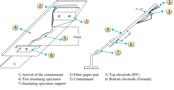
Figure 2.1 Chemical structure of silicone rubber [32] ... 2.3 Figure 2.2 Behaviour of water droplet on an insulating surface... 2.6 Figure 2.3 Construction details of a composite insulator ... 2.7 Figure 2.4 Typical end fittings for composite long rod insulators ... 2.7 Figure 2.5 Factors affecting the ageing rate of composite insulators ... 2.9 Figure 2.6 Ageing mechanisms of silicone rubber insulators [64] ... 2.12 Figure 2.7 Schematic diagram of the salt fog chamber test [92] ... 2.17 Figure 2.8 Schematic diagram of rotating wheel dip test [89, 93] ... 2.18 Figure 2.9 Test set-up for the inclined plane test according to the IEC 60587 standard [94]. ... 2.19 Figure 2.10 Leakage current patterns [100] ... 2.21 Figure 2.11 Possible contact angle values ... 2.22 Figure 2.12 water droplet on an inclined paln surface ... 2.23 Figure 3.1 Insulator with small hemisphere [123] ... 3.2 Figure 3.2 (a) Side view of part-spherical protuberance (b) Top view of an array of contiguous part-spherical protuberances [15] ... 3.3
Figure 3.3 Textured patterns: (a) Contiguous hexagonal, (b) Intersecting hexagonal, (c) Intersecting square and (d) Intersecting triangular [18] ... 3.5
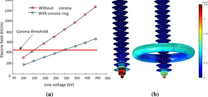
Figure 3.4 The IEC-60587 inclined-plane test sample with fitted stainless steel electrodes. Figure taken from [19] ... 3.8 Figure 3.5 Filter paper dimensions [19] ... 3.9 Figure 3.6 Electrodes dimensions (a) High-voltage electrode, (b) Ground electrode [19] .... 3.9 Figure 3.7 Maximum electric field intensification at different water drops [155]; for deformed droplets a mean value for Etan and Eabs at three different frames are considered ... 3.16 Figure 3.8 Photographs of water droplets on the insulator surface, and the corresponding droplet models used in the numerical simulations [157] ... 3.17 Figure 3.9 Examples of the E-field distribution surrounding three different designs of composite insulator end fittings [159] ... 3.19 Figure 3.10 Electric field. (a) Maximum electric field norm as a function of system voltage under dry conditions considering the effect of corona rings. (b) Electric field distribution on the surface of composite insulator with and without corona ring... 3.20
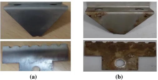
ii Figure 4.1 Conventional non-textured sample... 4.2 Figure 4.2 Zoomed detail of the 4mm intersecting hexagonal and intersecting square samples. ... 4.3 Figure 4.3 DC-AC High voltage tracking testing machine. ... 4.4 Figure 4.4 Touch display of the DC-AC High voltage tracking testing machine. ... 4.5 Figure 4.5 Ammonium chloride and isooctylphenoxpolyethoxyethanol ... 4.6 Figure 4.6 (a) A close-up of a rectangular sample in the test compartment, (b) Filter-paper 4.7 Figure 4.7 Schematic representation of comparison methodology. ... 4.8 Figure 4.8 Flowchart of the test procedure. ... 4.9 Figure 4.9 Pictures of the electrodes. a) before IP test, b) after 6 h of IP test for intersecting square sample under DC ... 4.10 Figure 4.10 Photographs of intersecting square samples tested at 3 kV DC showing the discolorations on the surface ... 4.12 Figure 4.11 Close-up images of the eroded areas of silicone rubber textured samples (intersecting square) tested at DC voltage ... 4.13 Figure 4.12 Photographs of intersecting hexagonal samples tested at 3 kV DC showing the discolorations on the surface ... 4.14 Figure 4.13 Close-up images of the eroded areas of silicone rubber textured samples (Intersecting hexagonal) tested at DC voltage ... 4.16 Figure 4.14 Line of short and parallel discharge channels ... 4.17 Figure 4.15 Progression of the discharges activities on the surface sample ... 4.18 Figure 4.16 Distribution of arcs near the ground electrode ... 4.18 Figure 4.17 Discharge activity distribution. (a) Line of short and parallel discharge channels, (b) Arcs near the ground electrode ... 4.19 Figure 4.18 Close-up images of the eroded areas of silicone rubber textured samples (Intersecting hexagonal and square) tested at AC voltage ... 4.20 Figure 4.19 Zoomed view showing expulsion of droplets of the liquid contaminant at the smooth sample under IPT ... 4.21 Figure 4.20 Visual images showing different cases of discharges distribution at the smooth surfaces during the early stages of the DC test ... 4.21 Figure 4.21 Evolution of tracking on the non-textured sample at the DC test ... 4.22 Figure 4.22 Visual images showing different cases of discharges distribution at the smooth surfaces during the early stages of the AC test ... 4.22 Figure 4.23 Evolution of erosion on the non-textured sample at the AC test ... 4.23
iii Figure 4.24 Close-up images of the eroded areas of non-textured sample tested at AC voltage ... 4.23 Figure 4.25 Leakage currents measured during the IP tests for intersecting square samples under DC and AC voltages ... 4.24 Figure 4.26 Box and whisker plots for each hour of the DC test on intersecting square samples ... 4.25 Figure 4.27 Box and whisker plots for each hour of the AC test on intersecting square samples ... 4.26 Figure 4.28 Box and whisker plots for each hour of the AC test on one intersecting square sample ... 4.27 Figure 4.29 Leakage currents measured during the IP tests for intersecting hexagonal samples under DC and AC tests ... 4.27 Figure 4.30 Box and whisker plots for each hour of the DC test on intersecting hexagonal samples ... 4.28 Figure 4.31 Box and whisker plots for each hour of the AC test on intersecting hexagonal samples ... 4.28 Figure 4.32 Illustration of the insulator surface ageing mechanisms under inclined plane test ... 4.30 Figure 4.33 Erosion process ... 4.31 Figure 5.1 General procedures for FEM simulations [174] ... 5.3 Figure 5.2 Textured silicone rubber sample. ... 5.4 Figure 5.3 Used electrodes ... 5.4 Figure 5.4 Textured silicone rubber samples: "A" Contiguous hexagonal, "B" Intersecting hexagonal and "C" intersecting square ... 5.5 Figure 5.5 Different diameters of hemispherical protuberances of the sample "A" contiguous hexagonal, sample "B" hexagonal intersection of overlapping protuberances and sample "C" intersecting square arrangement ... 5.6 Figure 5.6 Surface protuberances: (a) Area of Protuberance, (b) Edge of protuberance for textures "A", "B" and "C" ... 5.7 Figure 5.7 Calculated weights for different patterns ... 5.8 Figure 5.8 Mesh discretisation of four insulators ... 5.10 Figure 5.9 Equipotential lines of insulators ... 5.12 Figure 5.10 Comparison of the potential distribution for different design ... 5.13
iv Figure 5.11 Comparison of the electric field strength distribution on the surface of the silicone rubber insulation ... 5.14 Figure 5.12 Variation of creepage distance for all models and different range of diameters ... 5.15 Figure 5.13 Electric field distribution along silicone rubber insulators for different diameter ... 5.16 Figure 5.14 Maximum electric field strength for different configuration and different range of diameter ... 5.17 Figure 5.15 Maximum electric field along textured silicone rubber insulators under dry conditions as a function of system voltage ... 5.18 Figure 5.16 Pollution distribution shape on the textured surfaces ... 5.19 Figure 5.17 Accumulated pollution volumes... 5.20 Figure 5.18 Schematic of a textured silicone rubber "A" with 10 mm of the diameter of hemispherical protuberances under polluted conditions ... 5.21 Figure 5.19 Tangential electric field distributions along the surface for different patterns . 5.24 Figure 5.20 Electric potential along the surface for different patterns ... 5.25 Figure 5.21 Electric field strength distribution along the sample "A" under clean and uniformly polluted surface condition ... 5.26 Figure 5.22 Electric field strength distribution along the sample "B" under clean and uniformly polluted surface condition ... 5.26 Figure 5.23 Electric field strength distribution along the sample "C" under clean and uniformly polluted surface condition ... 5.26 Figure 5.24 Electric field strength distribution along the smooth sample under clean and uniformly polluted surface condition ... 5.27 Figure 5.25 Design of experiment process ... 5.29 Figure 5.26 Configuration of non-uniform pollution distribution: (a) Non-uniform pollution layer of 10, 25, 40 mm in middle of textured model, (b) Location of the pollution band ... 5.30 Figure 5.27 Normality plots with 95% confidence intervals of the electric field ... 5.36 Figure 5.28 Pareto diagram for electric field ... 5.36 Figure 5.29 Effects of the factors T, W and L on the maximum electric field ... 5.37 Figure 5.30 Graph of interaction between T, W and L on the maximum E-field ... 5.38
v
L
IST OF
T
ABLES
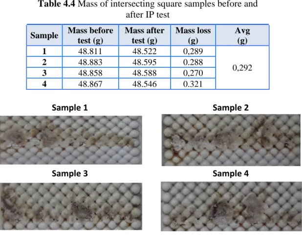
Table 2.1 Classification and description of composite insulator deterioration ... 2.14 Table 2.2 Classification and description of composite insulator damage. ... 2.15 Table 2.3 Criteria for estimation of the hydrophobicity classification (HC) [108] ... 2.23 Table 3.1 Theoretical classification of textured patterns (Table adopted from [18]) ... 3.7 Table 3.2 Values of the test voltage, series resistance and contaminant flow rate (Table taken from [19]) ... 3.10 Table 3.3 Summary of inclined plane test results. ... 3.12 Table 3.4 Equivalent DC voltages of the inclined plane test ... 3.13 Table 4.1 Properties of silicone rubber materials [126]. ... 4.3 Table 4.2 Discharge phenomena on the intersecting square samples during the test ... 4.11 Table 4.3 Mass of the top and bottom electrodes before and after IP test for intersecting square sample under DC ... 4.12 Table 4.4 Mass of intersecting square samples before and after IP test ... 4.13 Table 4.5 Discharge phenomena on the intersecting hexagonal samples during the test ... 4.15 Table 4.6 Mass of the top and bottom electrodes before and after IP test for intersecting hexagonal sample under DC ... 4.16 Table 4.7 Mass of silicone rubber textured samples (Intersecting hexagonal) samples before and after IP test ... 4.16 Table 4.8 Mass loss of textured silicone rubber samples and electrodes at AC test ... 4.19 Table 5.1 Calculated physical quantities of the used samples ... 5.8 Table 5.2 Calculated lengths between electrodes (mm) ... 5.25 Table 5.3 Values of parameters at various levels ... 5.28 Table 5.4 Taguchi design L (33) and simulation results of maximum E-field ... 5.32 Table 5.5 Values of the model coefficients ... 5.32 Table 5.6 ANOVA for maximum E-field ... 5.33 Table 5.7 Verification of ANOVA on the maximum E-field ... 5.34
vi
L
IST OF
A
BBREVIATIONS AND
S
YMBOLS
List of Abbreviations
2-D /3-D Two / Three dimensionsAC Alternating Current ANOVA Analyse of variance
ASTM American Society for Testing Materials ATH Alumina Trihydrate
BEM Boundary Element Method CTV Constant Tracking Voltage DB Dry-Bands
DOE Design of Experiment Method
EPDM Ethylene-Propylene-Diene Monomer EPM Ethylene Propylene Monomer
EPR Ethylene-Propylene Rubber EPRI Electric Power Research Institute FEM Finite Element Method
FRP Fibre Reinforced Plastic HC Hydrophobicity Classification HTV High-Temperature Vulcanizing HV High Voltage
HVDC High-Voltage Direct Current
IEC International Electrotechnical Commission IPT Inclined-Plane Test
IRT Infrared thermography ITV Initial Tracking Voltage LC Leakage current
LMW Low Molecular Weight LSR Liquid Silicone Rubber PDMS Polydimethylsiloxane RMS Root Mean Square
RTV Room-Temperature Vulcanizing RWDT Rotating Wheel Dip Test
SiR Silicone Rubber
STRI Swedish Transmission Research Institute USA United States of America
vii
Symbols
kV Kilovolt
CH3 Methyl Group Si-O Siloxane bond Si Silicon
O Oxygen
°C Degrees Centigrade Al (OH)3 Alumina trihydrate SiO2 Silica
% Percent
θc Static contact angle SiO2 Silica
NaCl Salt (Sodium chloride). mA Milli-ampere
µA Microampere
° Degree (angle) θ Inclination angle
θa Advancing contact angle θr Receding contact angle E Electric field
J Leakage current density P Power dissipation a Radius of the circle b Radius of the sphere c Height of the sphere
Ap Surface area of the protuberance At Area of the triangular plane surface σ Conductivity
I Current
α Area factor β Creepage factor αβ Power density factor
Hz Hertz mm Millimetre V Volt S Seconds ml Micro litres min Minute NH4CL Ammonium chloride g Gram
viii
m Sample mass
v Sample volume
ρ′ Density of the material ε Permittivity
σ Conductivity
εr Relative permittivity ρ Space charge density
T Thickness of the pollution layer W Width of the pollution layer L Location of the pollution layer
P-value Probability of testing the significance of the null hypothesis F Standard statistical Coefficient "F"
p. 1.1
Chapter 01
I
NTRODUCTION
1.1. Background
Developments of the modern world depend significantly upon a continuous electric power supply. With growing demand, utilities must provide secure and reliable power delivery while maximising the performance of the power distribution system from both technical and economic standpoints. High voltage power lines have been widely used to transmit the electric energy from the power stations to the end users. Outdoor insulators are among the key components in the electric power transmission network, essentially required for two primary purposes: 1) to isolate the transmission tower from the high-voltage source, and 2) to provide a load-bearing platform capable of supporting heavy overhead conductors well above the ground [1].
Two main categories of insulators have been employed for overhead lines depending on the material used: Ceramic and polymeric insulators. Decades of in-service performance have demonstrated that ceramic insulators, made of porcelain and glass, show good performance, they provide excellent resistance to material degradation caused by ultraviolet (UV) radiation and discharge activities [2]. However, they suffer from having hydrophilic surface properties, which means that water can easily form a continuous conductive film along the creepage path, thus allowing high surface leakage currents to flow on their wetted surfaces. Also, they have disadvantages related to their mass, the costs of their installation, their fragility under mechanical and vandalism constraints.
During recent decades polymer insulators have been introduced and widely used due to their better pollution performance. Insulators made of polymer materials are often called composite or non-ceramic insulators. Non-ceramic insulators offer several advantages over porcelain insulators. The most important advantage of polymeric insulators is their better performance in the polluted environment due to
p. 1.2 their good hydrophobic surface property under wet conditions such as rain, fog and dew [3]. This water repellent property forces water to be deposited in a form of discrete beads. The reduction of surface wetting, therefore, leads to a reduction in the discharge activity and dry band arcing on the polymeric surface and ultimately improves the anti-pollution performance. Moreover, they have high mechanical strength to weight ratio, less prone to damage due to vandalism because of it elasticity surface, and reduced maintenance costs [4, 5].
A polymeric insulator consists of a core fiberglass rod, two metal end fittings, and polymer weather sheds, which are shaped and spaced over the fiberglass rod to protect the rod and to provide the required leakage distance. Silicone rubber is a polymer widely adopted for outdoor insulation. Unlike other polymers, like EPDM (ethylene propylene diene monomer), it retains its hydrophobic status throughout service life and, in addition, has the ability to transfer this hydrophobicity to the adhering pollutants.
1.2. Problem Statement
The hydrophobic surface of polymeric insulators offers a significant advantage compared with glass or porcelain. However, under severe ambient conditions, dry band formation is not totally eliminated, especially before hydrophobic recovery can occur in the overlaying pollution layer. The outside service environment consists of wetting in the form of rain, fog, dew and direct spray; pollutants from the sea and roads that are salted during winter months in cold climates; and also chemicals from industry. In addition, insulator housings are subjected to ultra-violet (UV), temperature extremes, over voltages due to switching and lightning surges, and mechanical loads due to wind and ice.
Unlike porcelain and glass, polymeric materials have weak chemical bonds that can substantially degrade over time and they are more susceptible to chemical degradation under the multiple stresses likely to be encountered in service. In addition, they suffer from cracking, crazing, erosion and tracking. Moreover, their life expectancy is difficult to evaluate [4].
p. 1.3 Changes in surface properties influenced by service and climatic conditions may eventually lead to a loss of surface hydrophobicity, thereby promoting the formation of a continuous conductive film on its surface. The resulting leakage current under system voltage generates resistive heating that evaporates water from the wet surfaces, risking the formation of dry bands [6].
One of the main factors contributing to the development of discharges on insulator surfaces is the electric field distribution on the insulator surface, which in turn controls the current density. The usually non-uniform field profile along the surface has peak regions in which dry bands are formed. High electric fields trigger corona and discharge activities that contribute considerably to premature degradation through surface tracking and erosion. Under extreme conditions, intense electric arcs could puncture the polymeric housing and, more seriously, cause insulation failure from severe deterioration [7, 8]
1.3. Textured Insulators
Pollution flashover constitutes the predominant parameter for the design and dimensioning of high voltage insulators [9]. The effect of the design on the performance of outdoor ceramic insulators has been widely investigated [10, 11]. It has been proved that the open profiles or aerodynamic designs are more preferred for desertic conditions. However, insulators with more corrugated ribs are preferred for foggy conditions [12-14]. In fact, increasing the creepage length of ceramic insulators through complex shapes have been as a good solution for anti-fog insulator design. However, this complex shape cannot be adopted for polymeric insulators. For this reason, a new polymeric insulator design has been patented recently [15], where the smooth insulating surface is replaced by a textured silicone rubber surface. This texture has been designed to improve the anti-dry band as well as the anti-fog properties of the insulators in polluted areas. This design presents the advantage of increasing the surface area and then can reduce the leakage current density. Moreover, this solution is able to increase the longitudinal creepage distance and to reduce the stress applied in specific areas [15-18].
p. 1.4 Textured patterns consist of intersecting or contiguous hemispherical protuberances. This raised geometry does not impede the removal of the insulator from the mould during casting. The main aim of textured surface is to lower power dissipation on the insulator surface by reducing both leakage current density and the electric field gradient. This design concept aspires to reduce tracking and erosion on the insulator surface and to improve the flashover strength under conditions of heavy pollution.
1.4. Objectives of the present work
During the last 40 years, extensive efforts have been made to achieve a better understanding of the aging in polymeric outdoor insulation materials, by employing different techniques to investigate the material characteristics and the changes in properties due to degradation. Several experimental and simulation techniques have been conducted to assess the surface degradation due to discharge activities, dry band arcing and high electric field. Simulations of the electric field over the surface of the insulators are intended to determine the high-stress regions on the surface of the insulator. The research programme of this thesis is divided into two parts (experimental and simulation) to investigate and describe the behaviour of textured silicone rubber insulators.
The objective of experimental research is to compare and contrast the accelerated ageing characteristics of textured SiR insulation materials using the inclined plane test under AC and DC applications.
The general objective of simulation research is to study the electric field and potential distributions along textured insulators, first, under dry and clean conditions and then, under various wet conditions. A commercially available software (COMSOL Multiphysics) based on the FEM is employed for the modelling and the calculation for the textured SiR insulators under different surface conditions.
The specific objectives of this research work can be summarized as follows: • To investigate the long-term aging performance of SiR polymeric insulators
with different profiles, with textured and non-textured designs using an inclined plane test (IPT) and to compare the surface degradation under AC and positive
p. 1.5 DC excitations.
• To prove the effectiveness of textured surfaces in reducing the thermal damage on silicone rubber insulation due to surface heating induced by surface discharges.
• To identify and demonstrate the optimum textured designs that show the maximum reduction of surface erosion.
• To evaluate the localised surface conductance on conventional and textured insulators by identifying and understanding the variation trends of the conductance and its distribution across the surface of each insulator.
• To investigate the potential and electric field distributions along silicone textured surfaces with different diameters of hemispherical protuberances at DC, under clean and dry conditions.
• To examine the effectiveness of textured material for electric field stress control around the polymeric insulator.
• To investigate the effect of uniform pollution layer on the electric field and potential distribution along the textured silicone rubber patterns.
• To study the impact of non-uniform pollution layer on the electric field. The mathematical and statistical analyses have been used to evaluate the contribution of the studied factors and their interaction on the total variation of the electric field.
1.5. Methods
In order to achieve the objectives of this research work, numerical and experimental studies were performed. Each of them follows a methodology whose different steps are described below.
For experimental methods, a series of laboratory experiments were performed in the Power Systems Laboratory at American University of Sharjah, (UAE). These experiments were carried out using the DC-AC high voltage tracking testing machine, which is specially designed to perform the inclined-plane test (IPT).
The IPT is one of the most successful experiments to test the resistance to tracking and erosion for polymeric insulator and is described in the IEC 60587
p. 1.6 international standard [19]. Rectangular standard size samples are mounted at a 45° angle and subjected to high voltage stress. A salt contaminant solution is fed from the top of the sample and traverses the test surface. The test is designed to encourage the formation of dry-bands and surface discharges in order to monitor surface erosion and tracking. A series of tests at AC and positive DC were performed on two different rectangular SiR designs (smooth and textured) to study their aging performance and the degradation levels on each insulator surface. A visual video camera was used in order to record any indications of aging on the surface of the tested insulators.
For numerical analysis, they can be used to calculate the electric field and voltage distribution along textured silicone rubber surface under clean and different polluted conditions. Three-dimensional (3D) models of different textured surfaces were designed by Computer Aided Design (AutoCAD) software package. These samples were imported into COMSOL Multiphysics 4.3b for computation purposes. In the case of non-uniform pollution distribution, we have combined the finite element (FEM) with the design of experiment method to investigate and describe the behaviour of textured SiR Insulators.
1.6. Contribution of the present work
1) The standardised test methods for outdoor polymeric insulators are (a) salt-fog tests (b) clean-salt-fog tests (c) rotating-wheel tests and (d) inclined plane tests (IPT). Of these tests, the IPT has been widely utilized in the industry and even at the research scale. Recently, many tests were carried out for evaluating resistance to track the erosion of silicone rubber textured patterns used under AC voltage according to the inclined plane test methods indicated in the IEC 60587 standard [16-18, 20, 21]. However, no research has been carried out to investigate the behaviour of textured insulators under DC voltage according to the IPT. Therefore, the originality of the experimental study is to evaluate and compare the performance of textured insulators and conventional insulators at DC voltage by using the IPT. Also, the textured and conventional surface insulators degradation under AC and positive DC voltage were investigated.
p. 1.7 2) Electric field analysis around high-voltage insulators is with extreme importance during the development of new polymeric insulators design. The numerical method can be used to estimate the electric field strength because it is considered an economical and efficient way. Recently, the finite-element method (FEM) has been widely employed in HV engineering and numerous models have been developed for clean and polluted insulators [22-25]. However, to the best of our knowledge, no numerical models regarding textured insulator based on the FEM method were developed.
The originality of numerical study lies in aspects that can be described as follows:
• The maximum electric field is calculated taking into account various available patterns of hemispherical protuberance having different diameters under clean condition.
• A statistical model based on the design of experiment methodology is developed to study the maximum electric field in a textured insulator polluted in a non-uniform way. This work takes into account three factors characterizing the distribution of the pollution layer. The plan used provides much information for a better interpretation of the electric field under different pollution conditions.
1.7. Thesis Organization
This thesis is divided into six (6) chapters. In this chapter, a general introduction of this thesis is given. Also, the research objectives, used methods, and the main contributions of this work are briefly described.
Chapter 2 provides a literature review of high voltage polymeric insulators, particularly SiR Insulators. General insights into polymeric insulators including key advantages, chemical composition structure of SiR Surfaces, structural design, loss and recovery of SiR surface hydrophobicity, and factors contributing to the ageing or degradation process are presented. In addition, a review of the proposed methods for laboratory testing of polymeric insulators and the different diagnostic techniques currently available are presented.
p. 1.8 Chapter 3 describes the design principles of textured patterns used in this study. The IPT setup and methods are described. In this chapter, the literature review of the research work pertained to the erosion mechanism in the IPT is presented. Also, the literature review of tests carried out for evaluating resistance to the erosion of silicone rubber textured patterns in standard AC IPT are presented.
Chapter 4 presents the silicone rubber samples (conventional plain-surface and textured) used in experimental study, in addition to the equipment and procedures used for the experiments to investigating the performance of silicone rubber insulators. The tests were performed according to IEC60587 to compare the aging performance, especially the resistance to erosion, of SiR polymeric insulators under AC and positive DC. Analyses and interpretations of the whole results obtained in the experiment are presented in this chapter.
Chapter 5 presents the investigation of electric stress on textured and non-textured polymeric insulators by means of computer simulations. These simulations are intended to identify regions of the high electric field stress over the insulator surface. A commercial finite element package is employed for insulator modelling to determine electric potential and field distribution along the distance between electrodes under dry-clean and wet-polluted surface conditions, with uniform and non-uniform pollution models. The simulation results are discussed in this chapter.
Chapter 6 presents general conclusions based on the findings in this study, and proposed some suggestions for future research.
p. 2.1
Chapter 02
HIGH
VOLTAGE
COMPOSITE
INSULATORS
2.1. Introduction
Polymeric insulators for outdoor applications have been commercially produced for more than four decades, and the demand is increasing rapidly due to their encouraging performance under diverse conditions. Massive deployment of polymeric insulators throughout the power industries has resulted in large-scale research investigations aimed at enhancing in-service operation that could last for at least thirty to forty years, just as was the case of their ceramic counterparts.
This chapter describes composite insulators and then discuss the degradation and failure modes of these insulators with a particular emphasis on the origin of defects and their consequences. Also, a review of the methods proposed for the laboratory testing of polymeric insulators is presented. Finally, the different diagnostic and monitoring techniques of composite insulators currently available are presented.
2.2. Composite insulators for high voltage
The selection and acceptance of outdoor insulators in high voltage equipment’s rely on the assurance of good and long- term stable properties of these products. Life time’s ranging for a few decades and very low failure rates are desired.
In 1950’s United State of American (USA) started the use of polymeric insulators, the practical performance of these insulators was far less than satisfactory, with a number of problems and failures made the insulators unpopular in the market [26].
However, in 1970’s, polymeric insulators came into spotlight with the development of Fibre Reinforced Plastic (FRP) technology with improved housing material; the reliability of polymers has improved significantly [27]. Power utilities started using composite insulators and have become popular in high voltage
p. 2.2 applications due to their better pollution performance, lightweight, resistance against vandalism etc, steadily increasing their share on the market when compared to the traditional insulators made of porcelain or glass.
2.2.1. Composite insulation materials
Several types of polymeric materials have been developed by manufacturers, each with specific properties. In the field of outdoor insulators, three classes are particularly used: epoxy resins, Ethylene-Propylene Rubber (EPR) and Silicone Rubber (SiR) [28-30].
Epoxy resin materials are suitable for distribution insulation with a voltage up to 69 kV, and their long-term performance in clean environments is relatively successful. However, in polluted environments, their performance is unsatisfactory [28].
There are three types of Ethylene Propylene Rubber (EPR) in common use in overhead outdoor insulations: Ethylene-Propylene-Diene monomer (EPDM), Ethylene Propylene Monomer (EPM), and a co-polymer of ethylene-propylene and silicone [28, 29]. These materials are suitable for distribution and transmission systems with up to 765 kV [28]. Their long-term performance in clean environments has been successful. In polluted environments, their performance has been mixed, with some good experience, but generally, their long-term performance has been unsatisfactory.
Currently, the third generation of polymeric insulators is used extensively in service, where several experimental studies were conducted and appropriate modifications were made and adopted. The housing material of these insulators is mostly SiR. These materials have proven to be the most reliable for outdoor electrical insulation systems [31].
2.2.2. Silicone rubber used in outdoor insulation
The backbone structure of SiR is composed of alternating inorganic siloxane bond (Si-O) with methyl groups (CH3) added, forming polydimethylsiloxane (PDMS) as shown in Figure 2.1. The silicon-oxygen (Si-O) linkage in the silicone polymer chain is the same as that in sand, quartz, and glass. This bond is responsible for the
p. 2.3 good high-temperature stability of the silicones and their resistance to weathering, corona discharge, and oxidation by ozone, and ultra- violet (UV) radiation, thereby, ensuring a long-term stable performance over an extensive range of in-service conditions [5].
Silicone-based insulation housing can be classified with respect to the curing temperature to High-Temperature Vulcanizing (HTV), Room-Temperature Vulcanizing (RTV) and Liquid SiR (LSR). The HTV SiR is cured at high temperature, at 180°C, and pressure, and is commonly used in outdoor transmission and distribution as well as station post insulators. The RTV SiR can be supplied either in one- or two-component compounds. The first is cured at room temperature and commonly used in coating of ceramic insulators; whereas, the two-part RTV SiR cures at a lower temperature as compared to the HTV SiR, and is widely used for insulation housing of large equipment, such as transformer bushings in power stations. Unfilled LSR is supplied in two parts including the base polymer and curing agent, and can be cured at 200 °C within a few minutes [32].
Fillers are added to the SiR insulations to control different properties, such as mechanical stability and improve the resistance to tracking and erosion, which are added relatively in small amounts. The most common fillers used for SiR are Alumina trihydrate filler (ATH) (Al (OH)3) this provides better resistance to tracking and erosion [33] and Silica filler (SiO2) improves the mechanical strength of silicone compounds [34].
Figure 2.1 Chemical structure of silicone rubber [32]
Si
CH
3CH
3O
Si
CH
3CH
3O
Si
CH
3CH
3p. 2.4 2.2.3. Benefits and limitation of polymeric insulators
The material used for this work is SiR that has a number of advantages compared to the conventional glass and porcelain insulators; the main advantage of SiR Insulators is that their light weight. This makes it attractive in many ways, especially regarding installation and maintenance costs reduction [35]. Polymeric insulators have numerous other advantages including the following:
• Light weight: Polymeric insulators offer significant weight reduction compared to the corresponding ceramic insulation systems (much as 90%) [36]. There is less need for strong heavy support and cranes for installation, which results in easier handling and substantial savings in overall installation, operation and maintenance costs.
• Resistance to damage: Polymeric insulators with elastic properties help to prevent the risk of breakage during transportation or vandalism from gunshots that could lead to cascading failure as was experienced with ceramic insulators, this significantly reduces the loss [37].
• High mechanical strength: Polymeric insulators have a high mechanical strength to weight ratio that allows for longer spans and less expensive tower structures. They provide improved mechanical strength under bending, deflection and compression stress. It has been reported [38] that polymeric insulators passed mechanical tests under extreme conditions without any permanent damage.
• Hydrophobicity: Hydrophobic properties of silicone rubber significantly reduces the leakage current and the probability of dry band formation, which consequently results in reduced flashover voltages [28, 39- 41].
• Recovery of hydrophobicity: Even though silicone housing can temporarily lose its hydrophobicity under severe conditions, these materials are able to regain hydrophobicity after a sufficient resting period with the absence of discharge activity [42].
• Improved contamination performance: Polymeric insulators have low surface energy resulting in a water repellent or hydrophobic surface. This property can also be transferred to an overlying pollution layer [43] enabling improved pollution performance for insulation systems in highly contaminated regions such as coastal and
p. 2.5 industrial areas.
Despite the abovementioned advantages, polymeric outdoor insulators, however, suffer from a problem of material deterioration, known as ageing. This is primarily due to concurrent stresses; environmental, electrical and mechanical stresses encountered in a diverse range of service conditions.
• Polymeric materials which are organic in nature have weaker bonds, and hence susceptible to chemical change and compound degradations.
• Degradation can lead to changes in the surface properties of polymeric insulator, which can reduce electrical performance and increase the amount of surface discharge activity occurring in wet and polluted conditions, causing ablation of the material surface.
• Polymeric insulators can lose hydrophobicity due to a combination of exposure to UV, moisture, heat, and electric discharge activities that may occur on the insulator surface.
Due to utilities’ increased experience with these insulators through extensive research conducted in laboratory and field test stations, several problems have almost been eliminated by the use of new manufacturing techniques and excellent materials [44,45], the failure rate of polymer insulators has decreased to 26% of its initial value [46].
The new technology of polymeric insulators has possibilities for use in many applications of high voltage systems. However, their expected lifetime is still an issue of concern to some power utilities. Therefore, further researches are required regarding choosing an appropriate insulator design and manufacturing, investigating the composition of polymeric materials and the understanding of electrical, chemical, and mechanical deterioration mechanisms.
2.2.4. Hydrophobicity of silicon rubber
A hydrophobic surface is defined as a surface which is not readily wettable. Water on the surface does not form a continuous film, but forms individual droplets. The hydrophobic property of an insulating material is very important when speaking about the operating performance of the electrical equipment. On a hydrophobic surface
p. 2.6 no water film will be formed which will result in low leakage current between the high voltage and ground electrode. The silicone rubber surfaces are more hydrophobic than conventional insulators. This property contributes to the longevity of insulation materials.
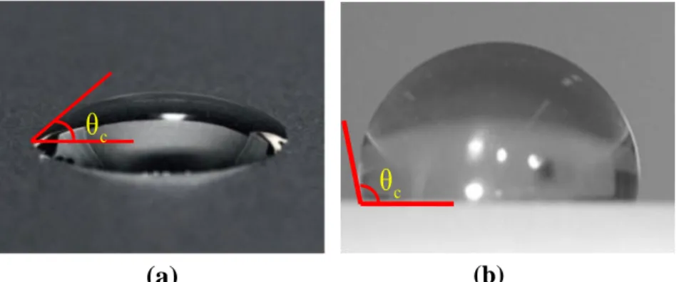
The simplest way of quantifying hydrophobicity is by measuring the static contact angle (θc) of a water droplet. Figure 2.2 illustrates the behaviour of a water droplet on a hydrophilic and hydrophobic surface. A contact angle θc ≤ 90° indicates that the surface is hydrophilic; while contact angles θc > 90° indicate that the surface is hydrophobic [47]. For new SiR it is approximately 100° while for glass and porcelain it is 44° and 47° respectively [48].
2.2.5. Silicone rubber insulators construction
Long-rod SiR insulators, which are used for different overhead lines and distribution systems, have the same design structure, but the size of these insulators and the end fitting shapes are variously based on the application for which they are used [50].
The SiR polymeric insulators are composed of three (3) main components (Figure 2.3) [4]:
1) The fiberglass core
The core is the central part of the polymer insulator made of fiberglass reinforced epoxy resin to provide the appropriate mechanical strength. Epoxy resins offer better electrical properties than polyester resins which are applied in some cases to reduce costs [4].
Figure 2.2 Behaviour of water droplet on an insulating surface
(a) Hydrophilic surface (Porcelain) and (b) Hydrophobic surface (Silicone) [49]
(a) (b)
c
θ
c
p. 2.7 2) The metal end fittings
The end fittings are generally made of metal (cast iron, aluminium alloy and forged steel [32]). Their shape is very important to limit the corona discharges that cause premature degradation of the polymeric material. The Figure 2.4 shows typical end fittings shapes. The dimensions comply with the IEC 60120 and IEC 61466 standards [51, 52].
Figure 2.3 Construction details of a composite insulator
Figure 2.4 Typical end fittings for composite long rod insulators
3) The SiR Housing (The sheds and sheath)
The core is encapsulated in a protective housing consisting of the sheds, and the sheath. The sheath protects the fiberglass core from damages due to electrical discharges and environmental stresses, and the sheds provide the required leakage distance.
The housing is manufactured from a variety of materials. EPDM and SiR are the two most common polymeric compounds used for outdoor high voltage insulation
Fibre-Glass Core
Silicone Rubber Sheds Silicone
p. 2.8 system. SiR compound is generally preferred because of its excellent electrical performance in various polluted environments. This is attributed to the strong hydrophobic surface properties, contrasted with EPDM which starts to show hydrophilic effects on exposure to prolonged wetting and electrical activity [53]. Numerous studies have shown that silicone rubber surfaces recover their hydrophobicity more quickly than EPDM surfaces [54, 55], and maintains its hydrophobic surface for a much longer time than the EPDM samples [33], this is the main reason for which SiR material is preferred to be used in heavily-polluted environments.
2.3. Degradation of polymeric insulator
Composite insulators are subjected, during their lifetime, to various combined stresses that cause more or less irreversible damage. These stresses can be grouped into three main categories, namely, environmental (temperature, moisture, UV sunlight, and humidity), electrical (discharge activities in the form of surface arcing or corona activity), and mechanical stress [56].
The polymeric materials, due to their weak organic bonds, are vulnerable to chemical change on exposure to these stresses, which consequently lead to degradation and ageing of the polymeric insulator [57]. The main factors leading to degradation of polymer insulators are illustrated in Figure 2.5.
For the pollution performance, the damage induced by surface discharges is of critical importance. The temperature produced by surface discharges can decompose the organic polymer, leaving traces of carbon forming resistive paths, a procedure called tracking [58, 59]. Erosion is the thermal damage associated with the loss of material from the polymer surface, especially in regions of localised discharge activity. Both tracking and erosion effectively reduce the performance of the insulator, and polymeric materials used on outdoor insulators should be assessed for their ability to resist such degradation.
Mechanical stress develops when strong winds move the line, causing oscillation. The consequent vibrations can cause the formation of fissures at the joint interface between the core and the metal flanges. In some cold-climate countries, ice
p. 2.9 accretion on both the conductor and weather sheds housing could generate additional loading stress on the polymeric insulator. In hot desert regions, the average temperature can easily reach 40˚C during the day and drop below 10˚C at night. This considerable change in ambient temperature results in a cyclic process of thermal expansion and shrinkage that can loosen the connection at the core-end fitting interface, affecting the mechanical strength of the polymeric insulators.
The aging processes in composite insulators are complex due to a large number of ageing factors and due to the effect of one stress over another [60, 61]. Spellman et al. [56] reviewed the main ageing factors leading to polymeric insulators degradation.
Figure 2.5 Factors affecting the ageing rate of composite insulators
2.3.1. Ageing mechanisms of silicone rubber insulators
The ageing mechanisms and flashover processes are different for traditional ceramic systems and composite insulators. This is mainly due to the higher hydrophobicity of the polymeric surfaces of composite systems and the different ageing characteristics [4, 62]. This is particularly true for silicone rubber. The insulator surface degrades in the great majority of cases under electric stress arcing
Environmental Stress
Organic or inorganic pollution (Fertilizers, acids salt algae,etc)
Mechanical Stress
Electrical Stress
Humidity, rain, fog and snow volume Ultraviolet radiation and ozone Wind direction and strength.
Temperature and pressure variations
Corona discharges Dry band arcing
Flashover voltage
![Figure 2.9 Test set-up for the inclined plane test according to the IEC 60587 standard [94]](https://thumb-eu.123doks.com/thumbv2/123doknet/3403670.98590/47.892.147.779.118.335/figure-test-inclined-plane-test-according-iec-standard.webp)
![Figure 3.8 Photographs of water droplets on the insulator surface, and the corresponding droplet models used in the numerical simulations [157]](https://thumb-eu.123doks.com/thumbv2/123doknet/3403670.98590/70.892.150.779.159.729/figure-photographs-droplets-insulator-surface-corresponding-numerical-simulations.webp)
![Figure 3.9 Examples of the E-field distribution surrounding three different designs of composite insulator end fittings [159]](https://thumb-eu.123doks.com/thumbv2/123doknet/3403670.98590/72.892.306.694.79.627/figure-examples-distribution-surrounding-different-composite-insulator-fittings.webp)