To cite this version:
Frances, Fabrice and Mifdaoui, Ahlem and Codogni,
Xavier and Fraboul, Christian An arbitrarily precise time synchronization
algorithm based on Ethernet Switch serialization. (2013) In: 25th Euromicro
Conference on Real-Time Systems (ECRTS13), 09 July 2013 - 12 July 2013
(Paris, France).
Any correspondence concerning this service should be sent to the repository
administrator:
[email protected]
O
pen
A
rchive
T
oulouse
A
rchive
O
uverte (
OATAO
)
OATAO is an open access repository that collects the work of Toulouse researchers and
makes it freely available over the web where possible.
This is an author-deposited version published in:
http://oatao.univ-toulouse.fr/
An arbitrarily precise time synchronization algorithm
based on Ethernet Switch serialization
Fabrice Frances, Ahlem Mifdaoui,
ISAE/DMIA University of Toulouse
Toulouse, France
{fabrice.frances | ahlem.mifdaoui}@isae.fr
Xavier Codogni, Christian Fraboul
ENSEEIHT/IRIT University of Toulouse
Toulouse, France
{xavier.codogni | christian.fraboul}@enseeiht.fr
Abstract—It turns out that trying to play a worst-case traversal time (WCTT) scenario on a real experimentation platform is a Real-Time problem with extremely tight con-straints. When two packets (with the same destination) arrive to two different input ports of a network switch within a time frame of only a few nanoseconds, the order of these packets in the output port queue will reflect this small nanoseconds arrival difference. Moreover, failing to emit packets within this tiny time frame will exhibit a different scenario than expected, potentially so radically different in farther places of the network that the behavior of the whole system seems affected by a butterfly effect. As we were trying to achieve the most precise clock synchronization we could with standard hardware, we have had the idea to turn this butterfly effect to our benefit and develop an arbitrarily precise time synchronization algorithm that only requires a standard Ethernet switch connecting the two hosts to synchronize and a third host on the network that will serve as a synchronization helper.
Keywords-clock synchronization; Ethernet switch;
I. INTRODUCTION
When trying to exhibit Worst-Case Traversal Time (WCTT) scenarios on a real network experimentation platform, we were faced with the problem of playing scenarios containing synchronized emission of frames in several End-Systems that do not share a common clock: most often, these worst case scenarios consist in simulta-neous arrivals of frames in a switching network element, for example Ethernet frames on an Avionics Full-Duplex Ethernet Switch (AFDX).
Let’s consider the simplest example of two frames (A and B) emitted by two different End-Systems, when these frames arrive to their connecting Ethernet switch and have the same destination. We assume tA andtB are the arrival times of the last bit of these frames in an ideal FCFS switch running in Store and Forward mode. Then we can observe that when tB < tA < tB + SizeB/C (where C is the capacity of the ouput port), then frame B will be retransmitted first starting from time tB (plus a small technological latency considered as 0 for this demonstration), whereas frame A will have to wait until tB+ SizeB/C before starting to be retransmitted. From a scheduling point of view, we can see that the same scenario of trafic would be observed on the output port of the switch, whatever the actual value of tA is in interval ]tB, tB+SizeB/C], i.e. retransmission of frame B starting
at tB, and retransmission of frame A starting at time tB + SizeB/C (thus frame A will have to wait for the end of retransmission of a part of frame B). However from a latency point of view, the worst latency we can observe is when tA is nearly equal to B (in this case we get the expected result where frame A has to wait for the full retransmission of B). So we can see that if we want to play the worst-case latency scenario, we have to be extremely precise and have tA very close to tB (but nottA< tB otherwise frame A would arrive first and be served without latency).
From this on, our quest was thus to find a way to synchronize our network End-Systems as much as we could. As we didn’t want to invest in specialized hardware like GPS clocks and instead propose a solution easily reproducible by any researcher, we tested the existing clock synchronization algorithms. First, Network Time Protocol [1]: the ntpd daemon is present in every Unix distribution. However, NTP is targeted for 1 ms synchro-nization at best, clearly not enough for our requirements. So, we then tested the Distributed Clocks of the Preci-sion Time Protocol [2][3], but again we couldn’t reach a tight enough synchronization: as the 1588 Working Group claims, microsecond precision shall be attainable with PTP, but only with dedicated hardware. There exists IEEE1588 Ethernet interfaces with integrated PTP, but this is not the case of most standard Ethernet interfaces found in PCs, where PTP has to be run in software. So, the software implementations we tested were not able to give a better than 10 µs synchronization. And studying the algorithms used in PTP revealed that the slave synchronization always rely on message exchanges sent on an Ethernet network, without taking into account the random latency effect of an eventual traffic arriving simultaneously on a switch.
Finally, we noticed that even the Robust Absolute and Difference Clock (RADclock) [4] has not taken benefit of the synchronization hardware that is available for free in every Ethernet network: the Switch.
II. THE FOUNDATION IDEA: ETHERNETSWITCH SERIALIZATION
Whether the switch is in Store and Forward or in Cut-Through mode, frames relayed to the same output port have to be serialized (two frames cannot be emitted at
the same time). When two frames arrive in a perfectly simultaneous timing on two input ports, this serialization process is usually a side-effect of the behavior of a centralized entity that takes the frames arrived in the input ports and relay them to the appropriate output queue. Were the relaying process be distributed among several entities (one per input port), then frames would also be serialized into the output port queue with a many-writer/single-reader scheme.
Since we were trying to have several End-Systems emit simultaneous frames and we had observed that a very small variation on the emission time drastically affects the order of serialized frames after the first switch, why not interpret this sequencing order as a proof that one frame arrived later? A general setup can now be given: all what is needed to synchronize two End-Systems is to have them connected to two input ports of an Ethernet switch with a FCFS policy (this is the most common policy in small and medium-sized switches), and an observer on a third output port. The two End-Systems just need to try to send a frame to the observer at the same time, and the observer will tell them which one was first or second. This is the only thing the observer is able to say, it is binary information: this End-System’s frame arrived first or second. For precise synchronization, it is useless to extract quantitative timing information: if the two End-Systems are nearly synchronized, the two frames will be serialized and arrive in a burst, one after the other, with no extra delay other than the standard InterFrame Gap (IFG) of Ethernet.
Now, with such a binary information (the order of frames is ”A, then B” or ”B, then A”), we will adjust one of the End-Systems’ clocks by an increment of time, and repeat the process, iteratively dividing the increment of time by a modified dichotomy. This is the point of the arbitrarily precise expression which sounds like an hyperbole: of course an infinite precision would only make sense with an ideal switch and ideal End-Systems able to adjust frame emission times with an infinite precision. But still, the algorithm proposed here has no limitation by itself: the precision will only be limited by the actual End-Systems and switch used, and precision can be arbitrarily improved by using faster End-Systems and/or switches when they become available.
III. INFORMAL DESCRIPTION OF THE PROTOCOL
The protocol is composed of only two types of mes-sages: messages sent by the clients to the synchronization helper host (the observer mentioned above will take the role of a synchronization server in this protocol), and messages sent by the synchronization server to the clients. The synchronization clients will never exchange messages together; communications take place only between a client and the synchronization server (helper).
Messages sent by the clients contain a timestamp value, denotedtclient
n , andn which is a sequence number starting from 0 (hence n identifies the messages sent by the clients). Messages sent by the synchronization server to
a client host contain a tuple of four values (∆n, δn, tserver
n+1 , n + 1), ∆n being interpreted as a request for clock adjustment,δna notification of the current precision, and the last two values forming a request to emit a client message numberedn + 1 at time tserver
n+1 .
A. Initialization steps for a very rough synchronization
These first steps are required to initialize communica-tion exchanges between the hosts to synchronize together and the synchronization helper. They are also used to reduce the large clock difference that might exist between the two client hosts at startup.
1) Step 1: Start server process on observer host C, it waits for two messages coming from client hosts A and B.
2) Step 2: Start client processes on hosts A and B; they send a client message to server C. The message contains the local time on the client host,tclient
0 . This is just to let the synchronization server have a rough idea of what time it currently is on the client hosts.
3) Step 3: On receipt of each of these first client datagrams, the synchronization server calculates an ap-proximated clock difference between the client and the server: ∆client= tserver
receipt− tclient0 Please note thattclient
0 is notthe accurate time of packet emission on the client. It is a timestamp written by the client in the message sent to the server. This timestamp is obtained by reading the current local clock prior to building and sending the datagram.
Conversely, tserver
receipt is not the accurate time of packet receipt on the server. It is the current time read on the server after the message read call returns. The thread that executes this blocking datagram read is resumed after a non-predictable amount of time due to slice execution of the currently active thread, followed by slice execution of other more prioritized threads.
However, the approximation on∆clientis anticipated to be lower than one second on non-overloaded hosts.
4) Step 4: The synchronization server C now plans a roughly synchronized emission (from both clients) to occur at timetserver
0 = t server current+ c
c is a constant delay bigger than the error in the approximated∆client, e.g. two seconds.
Thus, synchronization server C sends a request to each client, asking for a clock adjustment of∆0= −∆client
so that time on both clients becomes roughly equal to time on server C. In the same request, it also asks for a message emission at timetserver
1 . When the client has adjusted its clock as requested, this tserver
1 time is interpreted as a local client time, i.e. the client considers that tclient
1 ≈ tserver
1 .
B. The arbitrarily precise synchronization scheme
At the beginning of next step, a client has already received a request to send a datagram to the server at time tserver
n , withn being an iteration number (n is 1 when only the initialization steps above have been executed).
The following step is repeated until the desired syn-chronization precision is reached. The currently attained
precision is denoted δn and has been transmitted in the last server message alongside with the request for clock adjustment and the requested time for the next client message emission. Thus the value of δ0 has been sent to the clients in the last step of the initialization phase. Chosing a good value for δ0 will have an impact on the number of steps needed to attain a defined precision. However, it is useless to select a very small value like 1 ms, because in this case there is a possibility that the altered dichotomy has to do hundreds of 1 ms increments in the same direction. In the other hand, starting with a large value (like 1 second) only requires 20 steps to reach the 1µs precision.
1) Repeated step: Both clients actively wait for time tclient
n to happen (i.e. with an active loop) and then immediately send the requested datagram to the server. The two datagrams are received as Ethernet frames in the switch that connects the clients, and since the destination of the two datagrams is the same, the two Ethernet frames are serialized for retransmission on the output port that leads to the destination. The serialization process will be further detailed in next section.
The synchronization server will thus receive the two messages in one of the two possible orders (either the message from A followed by the message from B, or the message from B followed by the message from A). The received order tells which client host has its clock in advance compared to the other client host. So the synchronization server prepares a new request for clock adjustment: the client host whose message arrived first will be requested a clock adjustment of δn+1, while the other will be requested a clock adjustment of 0.
In the same message, the synchronization server also ask both clients to plan their next message emission at timetserver
n+1 = tservercurrent+ c.
The last parameter of the message is the precision delta that will be associated to the next iterated step. This δn+1
is calculated with the following rule: if the order of reception is the same as the one observed during the previous nearly-synchronized emission, then δ stays the same (i.e. δn+1 = δn) ; but if the order of reception is reversed, then δ is divided by two. The rationale for this altered dichotomy is discussed in next section.
IV. RATIONALE FOR THE PROTOCOL EFFICIENCY
The rationale behind the foundation idea is that the latencies between each of the synchronizing client hosts and the switch’s relaying entity are equal for both clients. More precisely, the delay of interest comes from the following sequence of events:
• a read of the client’s internal clock that determines the end of the active wait loop,
• the write of the client synchronization message, which is a system call that provides the protocol datagram to the UDP/IP send stack, including the final Ethernet driver, which in turn provides the Ethernet frame to the hardware Ethernet card (or interface),
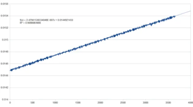
Figure 1. Measurement of clock difference (in seconds) between two non-synchronized hosts, over 3600 seconds (1 hour)
• the emission of the Ethernet frame,
• the propagation on the link that connects to the switch, delaying the reception of the emitted signal on the switch’s input port,
• the switch algorithm that senses the input ports for incoming frames and decides at which point a frame can be relayed to an output port’s queue (e.g. as soon as the destination address has been received, in Cut-Through mode).
The synchronization precision that our protocol will be able to reach is directly affected by variations in any of these points, so it is worthwhile explaining how jitter will be controlled. Also, it must be noted that the sequence of timely-controlled events has been reduced to a minimum: in other real-time distributed algorithms, large latencies with uncontrolled jitter exist in the network receiver stack and in the delivery of a received message to an application thread. Our solution fully removes these two sources of latency.
A. Controlling latencies from the client host to the switch
First, we assume the two clients have the same hard-ware/software combination: the same protocol client pro-gram is run on the same hardware and operating system. We will thus assume that the execution delay, between the read of the client’s internal clock and the I/O command sent to the hardware interface by the Ethernet driver, is
constant and identical on both clients. This assumption does not seem unrealistic, even if execution of other pro-cesses on a synchronizing client will introduce variations: we will try to reduce these interactions by implementing an active wait loop around the internal clock read, and no system call between this read and the datagram write, in order to reduce eventual thread switches. Of course, we will guard against clock skew. Our measures have shown very good consistency in stable conditions of temperature, as can be seen on Figure 1, showing a constant clock drift. Also, the execution time cannot be guaranteed to be exactly the same though, because of possible different content in the memory caches. However, the tight active wait loop will also help in keeping these memory caches filled with the desired content. Still, random hardware interrupts (disks or other hardware sources) might happen
in the synchronizing clients: we will assume that these random events will be quite infrequent and we will protect against these events with the altered dichotomy algorithm. Secondly, the length of the cables that connect the client hosts to the switch will also be assumed the same, even if this parameter has a smaller impact on the overall latency. Finally, the TxC (Transmit Clock) of the Ethernet inter-faces will be considered equal: any clock skew between these TxC will be compensated by the receiving switch.
We could also argument that a significant difference in the delay that separates the read of the client’s internal clock and the arrival of the frame in the correspond-ing switch’s input port is acceptable for our Real-Time application (playing a worst case traffic scenario): the same difference will exist when synchronously emitting the scenario, so what is really important for us is how we can have a fine control over the arrival of frames in the switch.
In conclusion, the only remaining source of uncon-trolled latency is the one present in the switch, before detecting an arrival of a frame and handling that frame (mainly relaying it to an output port). It is expected that some switches will scan their input ports in a loop, giving potential order inversion when frames arrive in a small time window, but we prefer to consider this switch behavior as a black box so that the protocol remains generic.
B. The altered dichotomy algorithm
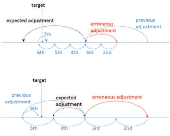
The altered dichotomy scheme has been designed to account for transient variations, e.g. additional latency in the client execution, due to some random event (disk inter-rupt for example). Also, even if no network application is executed at the same time as the synchronization protocol, there are always a few packets sent by daemons from time to time. In the emission protocol stack on the client host, such packets could delay a client synchronization message, affecting the order of arrival of the synchronized messages on the switch (and thus on the synchronization server). In such a case, the clock adjustment might take one erroneous direction which will hopefully be compensated by two half moves in the other direction (a normal dichotomy would never compensate a wrong move). This is exemplified by Figure 2, the upper part shows the case where the clock adjustment is wrongly halved, and the lower part shows the case where the clock adjustment should have been halved. The previous adjustment is depicted in order to show the last direction and amplitude of adjustment. In both cases, the next two adjustments will compensate the erroneous one.
V. CONCLUSION
This is a Work In Progress, the protocol is still in development as we are still working on the best way to trigger the emission of frames on the End-Systems so as to make the most of current hardware/operating system. But a number of ideas make this work promising, not only for our needs of synchronizing a network platform that
Figure 2. Robustness of the altered dichotomy algorithm in case of a wrong decision
aims to play worst case scenarios of traffic in Real Time, but also for any other distributed real-time application as soon as the nodes are connected with standard Ethernet technology:
• the use of the natural serialization that takes place in standard Ethernet switches, in order to provide binary information on which client host is late or in advance, • the reduction of the number and scope of untrolled sources of latencies: emission latency is con-trolled and message delivery latency in the destina-tion observer (synchronizadestina-tion helper) is not an issue. Moreover, the observer does not need to be connected to the same switch as the synchronizing clients: once client messages have been serialized by the first switch, they can cross any number of cascading switches before reaching the observer. Conversely, the observer could be integrated in the switch. • the robustness to transient errors with an original
al-tered dichotomy that brings further confidence in the capability of our algorithm to give the most precise synchronization, with standard operating systems and no extra hardware.
REFERENCES
[1] David Mills, Jim Martin, Jack Burbank, William Kasch, Network Time Protocol Version 4: Protocol and Algorithms Specification, RFC 5905, ISSN: 2070-1721
[2] Standard for a Precision Clock Synchronization Protocol for
Networked Measurement and Control Systems, PTP, IEEE
1588-2002 standard
[3] IEEE Standard for a Precision Clock Synchronization Proto-col for Networked Measurement and Control Systems, PTP v2, IEEE 1588-2008 standard
[4] Julien Ridoux and Darryl Veitch, Ten Microseconds Over LAN, for Free (Extended), IEEE Transactions on Instrumen-tation and Measurement (TIM) vol. 58(6), pp. 1841-1848, June 2009