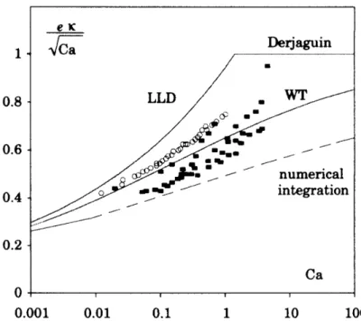
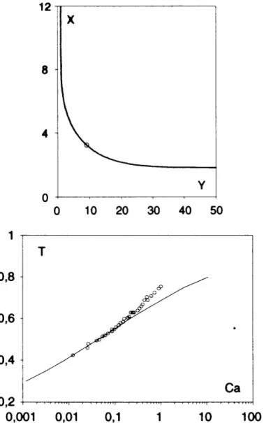
Gravity and inertia effects in plate coating
Texte intégral
Figure


Documents relatifs
47 Goss, Četiri stoljeća…, 190–191.. origins before the Tartar invasion, probably from the fourth decade of the 13 th century parallel to or slightly postdating Čazma
Fortis N.V., Archimedeslaan 6, 3584 BA Utrecht, Netherlands; Fortis S.A./N.V., Rue Royale 20, 1000 Brussels, Belgium The Royal Bank of Scotland Group plc, Head Office,
Therefore, objective of this study was to investigate whether the number of reported vertigo attacks was equiva- lent between two reporting strategies: (1) event sampling using
1 Division of Balance Disorders, Department of Otorhinolaryngology and Head and Neck Surgery, Maastricht University Medical Center, Maastricht, Netherlands.. 2 Department
BSWS Bandhu Social Welfare Society FHI Family Health International GAPSS Gay Auckland Periodic Sex Survey HAIN Health Action Information Network HAPP HIV and AIDS
The major strengths of national NTD programmes in the African Region include strong commitment from national governments, established NTD programmes in all
Section 3.1 lists improvements in the congestion control and loss recovery mechanisms specified in RFC 2581.. Section 3.2 describes further refinements that make use of
When NETED is used to create a file (that is, when it is invoked from command level with an argument which specifies the name of a file which does not already exist in the
