Science Arts & Métiers (SAM)
is an open access repository that collects the work of Arts et Métiers Institute of
Technology researchers and makes it freely available over the web where possible.
This is an author-deposited version published in: https://sam.ensam.eu Handle ID: .http://hdl.handle.net/10985/19563
To cite this version :
Maxime BOURGAIN, Thomas PROVOT, Xavier BONNET - Design and manufacturing of prosthetic feet for children as a multidisciplinary project for mechanical engineering students -International Journal of Engineering Education - Vol. 36, n°6, p.1791-1800 - 2020
Any correspondence concerning this service should be sent to the repository Administrator : archiveouverte@ensam.eu
Design and manufacturing of prosthetic feet for children as a
multidisciplinary project for mechanical engineering students
Bourgain, M.
,
Provot, T.
,
Bonnet, X.
Biographies of the authors:
Maxime Bourgain is an associate professor at the EPF - Graduate School of Engineering. He graduated from the ENS Paris Saclay School and holds a research master’s degree from the ENSAM Paris in biomedical engineering. He wrote his thesis on biomechanics and health engineering. His research domains of interest are sport and rehabilitation biomechanics. He is currently the head of the Engineering and Health Major programme of the EPF Engineering School and carries out his research at the Institut de Biomécanique Humaine Georges Charpak.
Thomas Provot is an associate professor at EPF - Graduate School of Engineering in France; he is graduate of the ENIM engineering school (École Nationale d’Ingénieurs de Metz) and holds a research master’s degree from in Mechanics, Materials, Structures and Processes, delivered in partnership between the ENIM engineering school, the University of Lorraine and the Arts & Métiers engineering school in France. He obtained a PhD in mechanical engineering at the University of Reims Champagne-Ardenne. He is currently doing his research at the Institut de Biomécanique Humaine Georges. His research activities are focused on the biomechanical study of performance criteria using embedded measurement in outdoor running.
Xavier Bonnet graduated from Arts et Métiers in 2003; he obtained his PhD in biomechanics at the Laboratoire de BioMécanique des Arts et Métiers (2006-2009). After six years in the Research and Development department of Proteor, he joined the Institute of Human Biomechanics of Arts and Metiers (Institut de Biomécanique Humaine Georges Charpak), where he conducts research in biomechanics of locomotion in order to develop prosthetic and orthotic systems to compensate for disabilities or motor deficiencies.
Design and Manufacturing of Prosthetic Feet for Children as a Multidisciplinary Project for Mechanical Engineering Students.
BOURGAIN Maxime1,2, PROVOT Thomas1,2, BONNET Xavier1
1 Institut de Biomecanique Humaine Georges Charpak, Arts et Metiers ParisTech, 151Bd de l’Hopital, 75013
Paris, France. Email : {maxime.bourgain ; thomas.provot ; xavier.bonnet} @ensam.eu
2 EPF Graduate School of Engineering, 3bis rue Lakanal, 92330 Sceaux, France
ABSTRACT
This paper presents the development of a prosthetic foot designed by engineering-school students. A complete workflow from needs definition to the production and testing was performed. The standards for adults were adapted to children, then a pre-design was performed, and a numerical model was realised to perform numerical testing. The production was carried out through additive manufacturing and the printed prosthetics were tested in flexion, and then in a motion analysis room. This project was aimed at making students put into practice their ability to design and test a mechanical product in a biomechanics context. Their learning outcomes were assessed during their oral presentations, their written reports and the testing session. Students gave positive feedback at the end of the semester about their feeling of the project.
Keywords: Biomechanics, Prosthetic feet, Mechanical design, Additive manufacturing, Medical device
1 INTRODUCTION
A prosthetic foot is a medical device which enables people with lower limb amputation to walk after a rehabilitation period. Modern prosthetic feet commonly incorporate flexible parts manufactured using carbon fiber composite materials, as it allows for the storage of energy during the stance phase and the return of energy for body propulsion during late stance. Nowadays, these feet are customised according to individual needs, but they are expensive and are therefore not suitable for low-income countries, nor are they suitable for children due to the morphologic changes that take place during a child’s growth [1]. Moreover, in developing countries, the demand for lower-limb prostheses is still higher than the number of prostheses that can be distributed [2].
Additive manufacturing is an opportunity to identify new designs satisfying the specific needs of children in low-income countries. Fused Deposit Modeling (FDM) has the potential to allow local production with an adapted cost [3]. Designing a 3D-printed prosthetic foot which could be used by children is a major mechanical engineering challenge.
Even though problem-based learning (PBL) is increasingly used in various pedagogical domains such as general engineering [4], few articles have been published on PBL for students in biomechanical engineering. And these were not focused on a global structure but focused on material aspects [5] or are only designed to promote engineering in general [6]. Teamwork has shown a high potential for pedagogy [7], however, its efficiency appears to be culturally dependant such as it was previously highlighted in Qatar [8]. And it seems to be depending on how accustomed students are to work independently. Thus this article presents an example of PBL for biomechanical engineering students.
This challenge was proposed as a multidisciplinary case study for mechanical engineering students. The pedagogic aim was to involve students throughout the design process from the needs definition to the delivery of the product. This process was divided into lectures, tutorials and lab sessions in order to guide students during the development process.
2 PRESENTATION: STEPS OF THE PEDAGOGICAL PROJECT The pedagogical objectives of this project were to:
- Make students put into practice their knowledge in engineering design. - Illustrate and put into practice new classes of rehabilitation device. - Learn how to use additive manufacturing tools.
- Understand and process data from research measurement tools in mechanics and biomechanics. - Make students question their modelling by taking into account experimental measurements. - Make students work in teams and manage themselves autonomously.
Mechanical engineering students were split into groups and worked in semi-autonomy for 150 hours. Each group designed, simulated, manufactured and tested their own prosthetic foot. For all steps, different pedagogical sessions were provided to develop this prosthetic foot.
This pedagogical project was performed in two French engineering schools: ENSAM Paris and EPF Graduate School of Engineering. Results presented in the article are focused on the latter, where the project was carried out with students in their fourth year of study, equivalent to the 1st year of a Master’s degree. Students were
global engineers who had followed a common course of study from their 1st to 3rd years, after which they
choose Health as their application domain. At this time, students had previously taken courses in Computed Assisted Design (CAD) and Finite Element Modelling (FEM), and, during the semester when this project was carried, they had classes about movement analysis and rehabilitation devices. One student was involved in the student society in charge of 3D printers.
2.1. Concept of operations
A first introduction of the project was given, developing the context and the main objectives. The students were able to summarise this course in a 10-line abstract of the “marketing brief”. The need definition was developed using the APTE® “Bull Chart”, and the Functional Analysis System Technics (FAST) to identify the functions of the prosthetic foot based on the environment [9], on the child, such as his/her daily life activities, and on the prosthetic device such as the connector between the prosthesis and the pylon.
2.2. Requirements and architecture
Risk analysis and regulation analysis were performed in order to draft a first version of the project specifications. The aim was to apply generic tools to the project in order to identify specific criteria and a testing level corresponding to the identified functions. Scientific publications focusing on prosthesis design were used for this analysis [3, 10].
The regulation aspect focused on the 93/42 European Medical device directive, the ISO 22523 and ISO 10328 standards [11–13] addressing the essential requirements and testing methodologies for prosthetics. As standards were developed only for adults, an adaptation of these documents was proposed by the engineering students in order to adapt the requirements and mechanical test methods for children’s prosthetics. The risk analysis was performed based on the template given in the ISO 14971 standard [14].
2.3. Detailed design
The state of the art was analysed through the analysis of the patent databases and followed by a creative session in order to identify innovative solutions. A pre-dimensioning study was performed on relevant designs using the beam theory according to the concepts of Olesnavage et al. [15] in order to identify the first geometrical dimensions of the prosthetic foot.
A first geometric outline was designed using the Computer Aided Design (CAD) method to numerically validate the envelope corresponding to shoe, given as an example for this project (Figure 1).
Figure 1: Example of a prosthetic foot design with the internal envelope of the shoe using the CAD software.
Then a finite element model of the prosthesis was iteratively created to assess geometrical and mechanical criteria using CatiaV5 software (Catia, Dassault Système, Velizy-Villacoublay, France). Mechanical tests were simulated to help the iterative design of the prosthesis [16]. Material properties were set to those of PLA (PolyLactic Acid) as it is a standard material for 3D printers.
Boundary conditions were set following the interpretation of the ISO 10328 standard [13]. The upper part in contact with the connector was clamped and the load was added to the part of the prosthesis corresponding to the toes, inclined by 20°. Two loading conditions (200N and 800N) were tested in order to validate, respectively, stiffness criteria based on toe displacement and mechanical resistance based on Von Mises stresses.
2.4. Implementation using FDM
The optimised design was then manufactured using a widely used FDM machine (Ultimaker 2, Ultimaker, Geldermalsen, Netherlands). Printing files (.gcode) were generated using Cura software (Cura, Ultimaker, Geldermalsen, Netherlands). Specific attention was paid to the printing parameters such as the model orientation according to the deposit plane, wall thickness and infill density.
2.5. Integration, testing and verification
As there were no specific standards for foot prosthesis design for children, mechanical tests were adapted for a 15kg child from the ISO 10328 standard methodology [12]. The mechanical tests were performed with an Instron tensile machine (Instron 5566, Instron, France). Designed feet were set up in the machine with a prosthetic connector (1K206, Proteor, Dijon France). The prosthesis was clamped to the lower fixed crosshead with an inclination of 20° (Figure 2). The load was applied to the feet through the upper movable crosshead. A first test at 200N was performed in order to verify the prosthesis stiffness. Stiffness was validated if the toe displacement was similar to the deflexion determined during the pre-dimensional analysis. A second test at 800N was performed to verify mechanical resistance. Resistance was validated if the prosthetic foot did not undergo plastic deformation.
Figure 2: Mounting the prosthetic foot in the tensile machine. 2.6. System validation
Clinical validation is necessary for the complete system validation; however this process is not suitable for an engineering-student project. Thus, the system validation was executed in a gait-analysis lab equipped with an optoeletronic system of 13 cameras (Vicon, Oxford Metrics, Yarnton, UK) and one force platform (OR6, AMTI, Watertown, USA). Using existing gait-analysis protocol, biomimetic parameters were highlighted for the specific design of prosthetic feet [16]. Prosthetic feet were fixed on prosthetic tibia loaded with weights of 15kg and were rolled manually from heel to toe on the force platform. This setup allowed for the measurement of foot and tibia kinematics and ground reaction forces in a loaded situation. The data was compared with literature about asymptomatic gait cycles [17, 18]. Those measurements permitted teachers to introduce the concept of the ankle quasi-stiffness which is commonly computed in the literature [19, 20].
2.7. Operation and maintenance
As the product of the project is not commercialized, an estimate of the operational commissioning is proposed through: a production cost estimation, an estimate of the price of the product, a comparative analysis of the competition and feedback on the main improvement expected for the developed project. This part is proposed in the context of a product distribution for developing countries through a Non-Governmental Organization (NGO).
3 Expected Results & student productions 3.1. Concepts and architecture
For the first steps, students were able the define specifically the requirements for the product (Figure 3).
Figure 3: “Bull Chart” of the prosthetic foot.
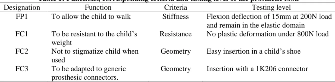
Then the different functions, criteria and the testing level were defined (Table 1). This methodology allowed the different groups to translate the function of the prothesis into mechanical characteristics and to develop a methodology to validate it.
Table 1: Functions, corresponding criteria and testing level of the prosthetic foot.
Designation Function Criteria Testing level
FP1 To allow the child to walk Stiffness Flexion deflection of 15mm at 200N load and remain in the elastic domain
FC1 To be resistant to the child’s weight
Resistance No plastic deformation under 800N load FC2 Not to stigmatize child when
used
Geometry Easy insertion in a child’s shoe FC3 To be adapted to generic
prosthesic connectors.
Geometry Insertion with a 1K206 connector
As there were no standards for testing a prosthetic foot for children, an adaptation of the work carried out by the American Orthotic and Prosthetic Association [21] on adults was made for children. For a 27cm foot at 1230N (corresponding to an 80 kg user), they recommend to provide 25mm of displacement, for the test configuration presented in Figure 2. This was adapted for a 15kg child as 15mm at 200N in the same configuration (foot size 16cm). The resistance threshold defined in the standard ISO10328 was also scaled to 800N for a 15kg user.
3.2 Detailed design
After the definition of the need and the function expressions, students were able to design creative models and to apply beam theory to the prosthetic foot in order to identify the general shape. Feet were represented as a cantilever beam where the deflection was associated with the stiffness criteria. A section of the beam was validated when the beam deflexion under the child’s weight reached a necessary displacement for the gait. Following the creative session, the first design was created using CAD (Figure 4).
Figure 4: First design from the creative session to the CAD model.
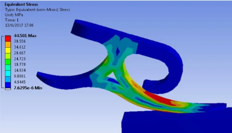
Using a finite element model, students were able to numerically test the criteria associated with the functions FP1 and FC1. Students had to parameterise their finite element model: meshing parameters, boundary conditions, possible symmetries, materials and contact management and then launching their simulation
(Figure 5). As the prosthetic feet had to be produced by additive manufacturing, special attention was paid to the material properties used in the simulation. Thus, an apparent elastic modulus was computed in the case of a chosen filling rate inferior to 100%. And as some geometries of the students were composed of several elements, especially when the toe part was composed of 2 blades (Figure 6), the geometrical contact during the simulation was also controlled.
Figure 5: Introduction of contact in the structure in order to resist the maximal load.
Function FP1 was validated when the numerical model was able to reach at 200N the necessary displacement (15mm) under the toes for gait. Function FC1 was validated when the numerical model presented a Von Mises stress beneath the elastic limit of the material under an 800N load. Functions FC2 and FC3 were validated when the total geometry was adapted to the shoe size and the generic connector respectively, on the simulation. After several iterations, students were able to propose a numerical model able to reach testing levels of all the functions.
3.3. Implementation, testing and verification
All designs were printed and fitted into the child’s shoe. Connectors were fixed to the prosthesis, allowing the mechanical testing to take place (Figure 6).
Figure 6: Results after the printing session.
Functions FP1 and FC1 were then experimentally tested on the tensile machine successively. Prosthesis solutions that did not exceed the elastic limit during the first test at 200N for stiffness were then tested at 800N for resistance. The first mechanical test was used to validate the stiffness criteria. Comparisons between the numerical and mechanical tests were then made; the results of one group are presented in Figure 7. On this figure it is possible to see a difference in the mechanical behaviour of the foot. This design consisted of a double blade, as it is possible to see on Figure 6, on the left of the right picture, and the contact of the two blades led to an increase in the apparent stiffness of the prosthetic foot. Designs with two blades generally fulfilled the two functions more successfully. At low loadings, the lower blade flexed and validated the flexibility criteria, then when the load was higher, the two blades made contact, increasing the resistance of the prosthesis which was enough to resist the second load at 800N.
Figure 7: Comparison between the numerical model (lower curve, in blue) and mechanical test (upper curve, in orange).
However, several differences from the numerical simulations were observed. Those differences may be explained by the estimation of the material properties. Indeed, FDM material cannot be considered as homogeneous due to the strings orientations and the filling parameters chosen. Moreover, temperature fluctuation in the prosthesis during printing may modify its properties. These differences could also be due to the infill density which was not always properly expressed during the pre-dimensional analysis or the first design. Then, the friction between blades was not accurately estimated and may have contributed to the difference. Boundary conditions could also be one of the causes of these differences. Indeed, during the simulation, the load area of application was fixed according to the geometrical grid and did not move with the strain of the prosthesis to better be in accordance with the mechanical test. New simulations should be performed to take into account the grid displacement and not only the applied load.
3.4. Validation
To test how close the functions of the prosthetic feet were to those of a biological foot, they were tested by reproducing the stance phase using a specific roll-over test. To do so, the weight of the user was simulated using mass applied at the center of mass (0,5m) and manually shifted backward and forward to represent the roll-over of the leg between -15° and +20° in the sagittal plane [17]. This test was performed in a motion analysis room, according to the right picture of the Figure 9. Markers were placed on the foot and the leg in order to compute the ankle sagittal angle and the ankle moment using inverse dynamics.
Figure 8 represents the vertical ground reaction force measured by the force plate and the vertical ground reaction force measured for an asymptomatic gait analysis. This permitted the students to identify if the prosthetic foot had the expected behaviour concerning absorption and restitution. However, as there is no active part for the prosthesis, the shapes were not identical. To better compare the two, the global stiffness was computed based on the ankle moment.
Figure 8: Comparison of the vertical ground reaction force between the prosthesis (light grey) and theoretical curve from asymptomatic subjects (dark grey).
Figure 9 represents the evolution of the ankle moment according to the ankle angle during this test with a well-designed prosthetic foot (dark grey) compared to the mean curve obtained at the ankle during the gait of asymptomatic subjects (light grey) [18]. This curve allows for the computation of the “ankle stiffness” during the stance phase and facilitates the comparison between the prosthetic leg, which has no ankle, and a human one. From heel strike (a) to heel off (c), the curve obtained with the prosthetic foot is close to the one obtained for an asymptomatic subject, proving that the stiffness of the prosthetic foot is appropriate for walking. During late stance, from heel off to toe off, asymptomatic subjects perform an active plantarflexion close to 15° whereas prosthetic feet return to the 0° neutral angle position.
Figure 9: Left: measured ankle moment regarding ankle angle. a: heel strike, b: foot flat, c: heel off, d: toe off. Right: corresponding experimental setup.
3.5. Operation and maintenance
The students suggested distribution of the product through an NGO. The cost of the product was estimated following a cost study of the design steps including: the cost of the time spent by engineers, prototyping costs (production, technician, maintenance, and raw material), tests and software; and a cost study of production including: machines, operators and raw materials proportionate to the number of samples and maintenance and shipping proportionate to the number of batches. During this stage of the project students were able to propose an overview of the lifespan of the product, such as the recycling process, or the fatigue study.
4 PEDAGOGIC ISSUES 4.1. Skills and knowledge
This pedagogic sequence was created as an innovative class with a project-based learning approach. Students had to develop their own solution as there was no unique solution to the problem tackled. This project was designed to help students to acquire skills and knowledge identified as key elements for engineers.
The engineering skills that motivated the creation of this project were mainly: ability to tackle a complex problem, to work in a team, to create an innovative solution, to communicate via various means (written report, oral presentation), to autonomously learn and apply scientific knowledge for solving a technical problem, to deal with standards.
This project was also an opportunity to sensitize students and teachers to a particular handicap to ease inclusion of disabled people.
4.2. Pedagogic progress and evaluation
4.2.1 Organisation
Each team had to act as if they were an independent company. Students interacted with 3 different teachers with independent roles: a client, a project management referee and a technical expert (Figure 10). The technical expert was available during dedicated sessions. Those sessions were either classes in which the expert presented technical elements (e.g. finite element classes and practical sessions) or sessions in which the expert was available on demand as a consultant on specific technical needs. The testing sessions and the final presentation were considered as milestones told to the students at the beginning of the project.
The client was only present for the expression of the need at the beginning of the project and at the end for the evaluation of the whole project. The project manager referee was present during the scoping meeting and the final evaluation. All the three coaches contributed to the evaluations.
Twenty students took part into this project during the first year when this project was taught.
4.2.2 Evaluation
Students were evaluated in various manners, mainly by considering their regular deliverables. Deadlines were given at the beginning of the project and no deliverables were taken into account after the appropriate deadline. The first deliverable was a framework paper considered as a contract for agreeing on the project objectives, signed by the students and the client. This contract was a means of validating the agreement between students and client. The second deliverable was a mid-term presentation in the form of a report on the project’s progress. They had to convince the project manager that their work was on schedule and that their progress was enough to be on time for all milestones. A final presentation was given at the end of the project with all the three coaches present. Each group had to give a technical note before the presentation. Additive manufacturing and mechanical testing were performed externally, compelling students to deliver their computer-assisted designs and printing parameters on fixed dates. Descriptions of the milestones are illustrated in the Figure 10.
Figure 10: Organisation of the whole project with milestones and external coaches’ roles
An additional evaluation of the project was performed by the students at the end of the semester. In particular they were asked:
- “Did your project allow you to learn and/or allow you to put into practice your theoretical knowledge?”
“Yes”: 14 No”: 1
-
“Do you think the quantity of work was well balanced during the semester?”
Very satisfied: 1
Satisfied: 11
Average: 2
Unsatisfied: 1 - “Do you think this project fitted well with the rest of your Major Program?” Very satisfied: 12 Satisfied: 3 Average: 0 Unsatisfied: 0
4.2.3 Students’ deliverables
The minimum work expected to validate the teaching unit consisted of the achievement of the three first milestones, with their oral and written descriptions. All groups succeeded in the first mechanical test with the part remaining in the elastic domain (FP1). However, the G2 group had too large a deflection (19mm). Concerning the second test (FC1), G2 broke at 320N, whereas G1 succeeded but the prosthesis came out of the elastic domain with irreversible strain. The G3 and G4 groups succeeded in all mechanical tests. The evaluation grid for the first year group is given in Table 2. All groups were able to validate FC2 and FC3.
Table 2: Example of the evaluation grid. Group 1 Group 2 Group 3 Group 4 Coefficients
Issue presentation and understanding 1 1 1 1 2
Presentation of the expected technical behavior 1 1 1 0,75 2 Explanation of the design and justification of the
hypothesis adopted (sizing, MEF parameters, printing parameters, …)
0,75 0,5 1 0,75 4
Presentation of the practical sessions 0,75 0,75 0,75 0,75 4 Perspectives: suggestion of future work for
development, testing and distribution 0,5 0,25 1 0,5 2 Communication: speaking time during oral
presentation, respect of schedule, ability to synthetize information.
0,75 0,75 1 1 2
Success of mechanical test 1 1 0,5 1 1 2
Success of mechanical test 2 0.5 0 1 1 2
total 15.5 12 19 16.5 20
5 DISCUSSION
This project was presented as a pedagogic project for students in the penultimate year of a French engineering school. This project was promising from a pedagogic and a social point of view. For teaching purposes, students had to tackle all steps of design from the transformation of needs to system functions and then to develop their own solution. They developed hard skills of engineering: pre-dimensioning with simple models, mechanical-simulation design, 3D-printer use and mechanical-test design, for instance. But they also developed soft skills such as teamwork.
From the social point of view, students had to develop their devices with the perspective of having them produced at low cost in a country with these needs. This perspective was observed to be a motivation for them. To that end several further steps of validations should be performed. For instance, it would be necessary to validate with more details the biomechanical behaviour of the prosthesis, such as the global stiffness of the ankle, but also to estimate the lifespan of the prosthesis by testing the mechanical fatigue. An idea to increase the ecological involvement of the students would be to advise them to use recycled materials for the additive manufacturing as it has already been shown to be possible [22]. Then, developing a robust simulation would allow for reshaping of the validated design according to the varying heights and weights of children. And finally, appropriate structures should be identified to spread the methodologies for helping children who need prosthetic feet.
However, as this project was proposed in a new pedagogic programme, it was difficult to measure quantitative pedagogical improvement. Even though all the students did not answer the questionnaire, qualitative feedback showed a high level of approval of this project. Students in this year group have had to work on projects in teams for 2 years and appear to have got used to it, unlike the ones in Qatar [8].
5 CONCLUSION & PERSPECTIVES
This project was presented as a pedagogic project for students of penultimate year of a French engineering school. This project was promising for pedagogic and social point of views. For teaching purposes, students had to tackle all steps of design from the transformation of needs to system functions and then to develop their own solution. Students successfully put into practice their knowledge in engineering design and successfully developed at least a simple prosthesis design. They were also able to share their experience to improve their skills in additive manufacturing and to produce their prosthesis on time. They were able to process data measured in a research laboratory by a tension-compression machine and movement analysis tools. They were able to question their modelling based on experimental results. They also developed their ability to manage a project in a group and to regularly communicate about it. And finally, this project was perceived as a good way to apply their theoretical knowledge, and consolidate the PBL approach for teaching biomechanics in engineering school.
Acknowledgements
The authors would like to thank all colleagues that helped with the setup of this project, but also all the student groups from ENSAM and EPF engineering school that participated in this pedagogical project. More particularly the students of the “apprentissage” who helped to design the fatigue testing machine which is a next step for this work. And, also Eve Bennett who helped for the writing of English.
REFERENCES
[1] A. P. Arya and L. Klenerman, The Jaipur foot, Journal of Bone Joint Surgery. British volume,
90(11), pp. 1414‑ 1416, 2008.
[2] M. Sam, D.S. Childress, A.H. Hansen, M.R. Meier, S. Lambla, E.C. Grahn, J.S. Rolock, The
“shape&roll” prosthetic foot: I. Design and development of appropriate technology for
low-income countries, Medicine, Conflic and Survival, 20(4), pp. 294‑ 306 2004.
[3] A. M. S. Ibrahim, R. R. Jose, A. N. Rabie, T. L. Gerstle, B. T. Lee, and S. J. Lin,
Three-dimensional Printing in Developing Countries, Plastic and Reconstructive Surgery - Global Open,
3(7), 2015.
[4] A.D. Lantada and C. De Maria, Towards Open-Source and Collaborative Project-Based Learning
in Engineering Education: Situation, Resources and Challenges, International Journal of
Engineering Education, 35(5), 2019.
[5] A. Morss Clyne and K. L. Billiar, Problem-Based Learning in Biomechanics: Advantages,
Challenges, and Implementation Strategies, Journal of Biomechanical Engineering, 138(7), 2016.
[6] S. D. Teeter, N. S. Husseini, and J. H. Cole, Assessing changes in attitudes toward engineering
and biomechanics resulting from a high school outreach event, Journal of Biomechanics, in press,
2020.
[7] M. Borrego, J. Karlin, L. D. McNair, and K. Beddoes, Team Effectiveness Theory from Industrial
and Organizational Psychology Applied to Engineering Student Project Teams: A Research
Review, Journal of Engineering Education, 102(4), pp. 472‑ 512, 2013.
[8] X. Du, K. Kamal Naji, S. Sabah, and U. Ebead, Engineering Students’ Conceptions of
collaboration, group-Based Strategy Use, and Perceptions of Assessment in PBL: A Case Study in
Qatar, International Journal of Engineering Education, 36(1B), pp. 296‑ 308, 2020.
[9] B. de la Bretesche, La méthode APTE : analyse de la valeur, analyse fonctionnelle, Europe
entreprises, Petrelle. 2000.
[10] S. Hussain, Toes That Look Like Toes: Cambodian Children’s Perspectives on Prosthetic Legs,
Qualitative Health Research, 21(10), pp. 1427‑ 1440, 2011.
[11] Directive 98/79/EC of the European Parliament and of the Council of 11 October 2007,
https://op.europa.eu/, Accessed 03 December 2019.
[12]ISO 22523:2006, External limb prostheses and external orthoses — Requirements and test
methods, https://www.iso.org/, Accessed 03 December 2019. .
[13]ISO 10328:2016 Structural testing of lower limb prostheses — Requirements and test methods,
https://www.iso.org/, Accessed 03 December 2019.
[14] ISO 14971:201 Medical devices - Application of risk management to medical devices, 3,
https://www.iso.org/, Accessed 03 December 2019.
[15] K. M. Olesnavage and A. G. Winter V, Analysis of Rollover Shape and Energy Storage and
Return in Cantilever Beam-Type Prosthetic Feet, Proceedings of the ASME 2014 International
Design Engineering Technical Conferences & Computers and Information in Engineering
Conference, Buffalo, New York, USA, 2014.
[16] R. Figueroa and C. M. Müller-Karger, Using FE for Dynamic Energy Return Analysis of
Prosthetic Feet during Design Process, 25th Southern Biomedical Engineering Conference 2009,
Miami, Florida, USA, pp. 289‑ 292, 2009.
[17] C. Curtze, A. L. Hof, H. G. van Keeken, J. P. K. Halbertsma, K. Postema, and B. Otten,
Comparative roll-over analysis of prosthetic feet, Journal of Biomechanics, 42(11), pp.
1746‑ 1753, 2009.
[18] H. Pillet, X. Drevelle, X. Bonnet, C. Villa, N. Martinet, C. Sauret, J. Bascou, I. Loiret, F. Djian,
N. Rapin, J. Mille, P. Thoreux, P. Fodé, J. Paysant, P. Guérit, F. Lavaste, APSIC: Training and
fitting amputees during situations of daily living, Innovation and Research in BioMedical
engineering, 35(2), pp. 60–65, 2014.
[19] A. H. Hansen and C. C. Wang, Effective rocker shapes used by able-bodied persons for walking
and fore-aft swaying: implications for design of ankle-foot prostheses, Gait and Posture, 32(2),
pp. 181‑ 184, 2010.
[20] A. H. Hansen, D. S. Childress, S. C. Miff, S. A. Gard, and K. P. Mesplay, The human ankle
during walking: implications for design of biomimetic ankle prostheses, Journal of Biomechanics,
[21] « Research | AOPA – AMERICAN ORTHOTIC & PROSTHETIC ASSOCIATION ».
https://www.aopanet.org/resources/research/, Accessed 03 December 2019.
[22] Affordable
prosthetics
made
from
recycled
plastic
waste,
https://materialdistrict.com/article/prosthetics-recycled-plastic/, Accessed 03 December 2019).
LIST OF FIGURES & TABLES
Figure 1: Example of a prosthetic foot design with the internal envelope of the shoe using the CAD software. Figure 2: Mounting the prosthetic foot in the tensile machine.
Figure 3: “Bull Chart” of the prosthetic foot.
Figure 4: First design from the creative session to the CAD model.
Figure 5: Introduction of contact in the structure in order to resist the maximal load. Figure 6: Results after the printing session.
Figure 7: Comparison between the numerical model (lower curve) and mechanical test (upper curve).
Figure 8: Comparison of the vertical ground reaction force between the prosthesis (left) and theoretical curves from asymptomatic subjects (right).
Figure 9: left: measured ankle moment regarding ankle angle. Right: corresponding experimental setup. Figure 10: Organisation of the whole project with milestones and external coaches’ roles
Table 1: Functions, corresponding criteria and testing level of the prosthetic foot. Table 2: Example of the evaluation grid.