A newly conceived cylinder measuring machine and methods that eliminate the spindle errors
Texte intégral
Figure
Documents relatifs
The building of the atherosclerosis classification models based on the MIMIC-III dataset using the Microsoft Azure Machine Learning cloud-based platform allowed to carry
- Network/MAC protocol design: in unlicensed band (such as with LoRa networks), where transmitters are uncoordinated, it is a challenge to coordinate the node in a distributed
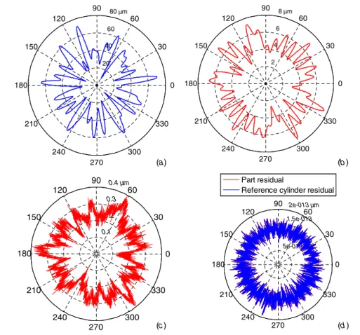
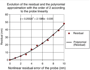
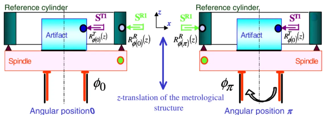
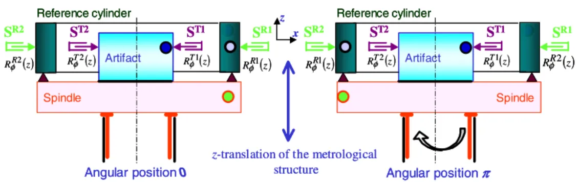
To improve the measurement, it is essential to identify the motion error of the mechanical guiding elements by applying some standard methods such as the reversal, multi-step
An original pure bending machine has been built to perform pure bending tests on specimens cut in thin sheets that can be used to identify elasto-plastic models taking into
sified into laboratory tests to determine the acute toxicity and the hazard to bumblebees, (semi) field tests, and brood tests.. The reproducibility and the significance of the data
Thus, ensuring that the evaluation function is in total adequacy with the user needs and that the problem instance sample used by the revision process is perfectly representative of
HmmCleaner with the default scoring matrix (for nt MSA, low similarity segments were detected on the cor- responding protein MSAs and then reported), (3) HMM-L: HmmCleaner with
Episodic shocks appear in both series — a 35 year high in woodcock numbers in the exceptionally cold winter of 1962/1963, and the 1929 stock market crash.. Neither series
