Science Arts & Métiers (SAM)
is an open access repository that collects the work of Arts et Métiers Institute of Technology researchers and makes it freely available over the web where possible.
This is an author-deposited version published in: https://sam.ensam.eu
Handle ID: .http://hdl.handle.net/10985/11197
To cite this version :
Ousmane FALL, Jean-Frederic CHARPENTIER, Ngac Ky NGUYEN, Paul LETELLIER, Eric SEMAIL, Xavier KESTELYN - Variable speed Control under Voltage and Current Limits of a 5phase PMSM drive in Healthy and OpenCircuited Modes Electric Power Systems Research -Vol. 140, p.507-516 - 2016
Any correspondence concerning this service should be sent to the repository Administrator : archiveouverte@ensam.eu
1
Abstract
This paper proposes a novel variable speed control strategy of a particular 5-phase Permanent Magnet Synchronous Machine (PMSM) in healthy mode and in fault mode by taking into account the constraints on voltages and currents. These constraints are related to the converter and machine design and sizing. The considered faults are open-circuited phase type (one phase, two adjacent phases and two non-adjacent phases). A variable speed control strategy is presented, including flux weakening operations. Based on analytical formulations, a numerical computation is proposed to bring out the torque-speed characteristics. This method allows to determine the current references which ensure the functioning of a 5-phase PMSM at variable speed while keeping phase voltages and currents below their limits. Theoretical, numerical and experimental results are presented. These results are compared in order to validate the proposed approach.
Keywords: synchronous multiphase machine, machine drives, fault mode, healthy mode, flux
weakening, reference current, numerical computation.
Variable speed Control under Voltage and Current Limits of
a 5-phase PMSM drive in
Healthy and Open-Circuited Modes
Ousmane FALL(1,2,3), Jean Frédéric CHARPENTIER(2), Ngac-Ky NGUYEN(3),Paul LETELLIER(1) , Eric SEMAIL(3), Xavier KESTELYN(3)
(1) Jeumont-Electric, 367 Rue de l'Industrie, 59460 Jeumont, France (2) Ecole navale et groupe des écoles du Poulmic CC-600 29240 Brest, France
(3)Arts et Métiers Paristech-L2EP 8 Bd Louis XIV 59046 Lille, France ousmane.fall@ecole-navale.fr
2 I. INTRODUCTION
Higher reliability of classical 3-phase drives can be achieved by oversizing the converter-machine set but this solution increases the cost of the whole system. Even if this oversizing is chosen, in case of an open circuit fault appears in one or two phases of the drive, the system cannot ensure a functioning even at reduced power.
Using multiphase drives instead of three-phase drives, makes possible to increase the power density, fault-tolerance capability and to reduce torque pulsations at low frequencies [1]-[2]. In fault mode, this kind of drives is able to work at a reduced power with satisfactory performances. This aspect is very important in systems which are designed for specific applications, such as offshore energy harvesting or electrical vehicles. As an example, in offshore renewable energy context, fault tolerant systems allow continuing to extract energy even if a fault occurs inside the generator drive.
Some research works propose to use multiphase machines to obtain a higher functioning reliability. Multiphase PMSM, especially 5-phase and 7-phase machines have been studied recently under open-circuit faults. The authors have demonstrated that it is possible to obtain a constant required torque if the fault is detected and identified. Several fault tolerant control strategies have been proposed to calculate optimal current references in order to maximize the torque to copper losses ratio. One of them is based on the Lagrange multiplier [3], [4]. A vector approach is proposed in [5], [6]. In [7], [8] an approach based on a geometrical representation makes possible to obtain optimal currents in both healthy or fault modes. A numerical approach is reported in [9] where fault tolerant controls of a 5-phase PMSM for different stator winding connections are proposed, which aim to calculate optimal currents in order to minimize ohmic losses and torque pulsations.
In the previous cited approaches the peak current, whose value can be quite depending on the parameters of the machine (cogging torque, harmonics of the back electro-motive forces
3 (back-EMF), etc.), is not considered. However, this peak current value is a key parameter for the sizing and the cost of the Voltage Source Inverter (VSI). As a consequence the proposed optimizations without taking into account this constraint can induce an important over cost.
The proposed paper will consider this constraint for the design of the control laws which be based mainly on methodologies described in [10-12] but adapted to a particular family of PMSM.
[10] and [11] aim to identify current expression for a 5-phase induction machine in order to have a constant torque under assumption of perfect sinusoidal winding functions. By keeping the same rotating field the drive can be operated in fault mode (one or two phase opened). In this case, only the rotating field corresponding to the first harmonic of magneto motive force (MMF) generates the torque.
The approach developed in [10, 11] has been adapted in [12] for trapezoidal back-EMF PMSM machines by considering first and third harmonics in the winding functions. The main difference with [10, 11] is that a third harmonic of the back-EMF is taken into account. As a
consequence, this 3rd harmonic of EMF is associated with a torque leading to ripples in fault
mode even if the first harmonic of the rotating MMF is controlled.
Moreover, the main limit of the proposed methods in [10-12] is that the limitations related to the converter voltage saturation and rated current at high speed operations (over the base speed) are not taken into account. In some existing situations, it is necessary to apply a flux weakening strategy for satisfying converter-machine voltage limit. This is particularly the case of electrical cars and renewable energy applications which are characterized by a large range of operating speeds. It can be noticed that for these kinds of application a new generation of machines with fractional slot tooth concentrated winding and obviously non sinusoidal winding functions has been developed [13].
4 Until now, flux weakening strategies have been studied in healthy operations [14-18]. In [19] an enhanced optimal torque control strategy in fault mode of a 5-phase permanent-magnet machine under flux weakening operation is studied but the voltage limits are not strictly respected. This work deals with flux weakening strategy even if the system is working in fault mode, but systems still exhibit torque ripples because of the non-sinusoidal back-EMF. The fault modes that are considered are only one phase opened or short-circuited so the cases where more phases are in fault are not taken into account.
In the proposed paper, a 5-phase PMSM machine with sinusoidal electromotive force will be considered, leading to less constraints for the control than in [12] and [19]. In this case, only controlling the first harmonic of rotating MMF allows to ensure a constant torque. As a consequence, only two degree of freedom (DOF) are required to maintain a constant torque and the other DOF could be used for other criteria of optimization. It is thus possible to manage voltage limitation related to flux weakening strategy. Even if their winding functions are not sinusoidal, as in concentrated winding machines, it has no impact on the torque if a sinusoidal back-EMF is considered.
The present paper studies fault tolerant capabilities of such PMSM with sinusoidal EMF in case of one or multiple open-phase faults. A control strategy which is able to keep a constant torque is proposed. For this purpose an analytical formulation of the corresponding currents references is presented. In a second step, numerical optimization (based on fmincon function of Matlab) is used in order to calculate the maximum torque and the corresponding current references under current and voltage limits. This approach allows to operate with flux weakening operations at high speed taking into account limitations coming from the drive (converter/machine) both in healthy and fault mode.
The paper is organized as follows. Section II is dedicated to the modelling of the multiphase drive. The control strategy of the system under healthy and fault modes with voltage and
5 current limits is presented in section III. Section IV gives some simulation results. In Section V, experimental results are reported. A conclusion is given in Section VI.
II. MULTIPHASE MACHINE MODELLING
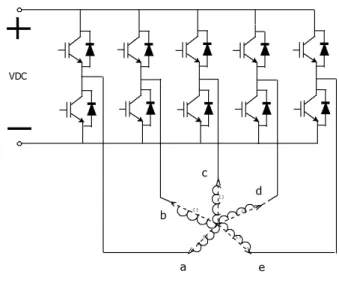
The drive considered in this work is shown in Fig.1.
To model the 5-phases PMSM, the followingassumptions are considered:
The 5 phases of the machine are regularly shifted
The saturation of the magnet circuits is not taken into account in the calculation of the
back electromotive forces (EMF) and the fluxes.
Windings are star connected
Armature reaction is not taken into account in the back-EMF waveforms
The voltage vector can then be written as:
s
d v R i e dt (1) where:
v va v v vb c d ve
T
T a b c d e is the stator flux vector
Ta b c d e
i i i i i i is the current vector
Ta b c d e
e e e e e e is the back-EMF vector
Rsis the stator resistance
Controlling a 5-phase PMSM in the natural phase frame is not an easy task because of the magnetic couplings that exist between the phase windings.
Applying a generalized Concordia and Park transformation, the voltages in the new reference frame can be obtained by [20, 21]:
6 0 0 s0 0di 0 v R i L e dt (2) 1 1 1 1 d 1 1 d s d d di q q v R i L p L i dt (3) 1 1 1 1 ( 1 1 5 1) 2 q q s q q d d di v R i L p L i dt (4) 3 3 3 3 d 3 3 3 d s d d di q q v R i L p L i dt (5) 3 3 3 3 q 3 ( 3 3 52 3) q s q q d d di v R i L p L i dt (6)
Where (vd1,vq1,id1,iq1) and (vd3,vq3,id3,iq3) correspond to the projection of the phase voltages
and currents in two independent rotating d-q frames respectively noted (d1q1) and (d3q3). As
mentioned in [20, 22], the first harmonic of currents, voltages, and back-EMFs is projected in
the (d1q1) frame and the third harmonics in the (d3q3) frame. The zero-sequence sub-system
(equation(2)) is only affected by multiple harmonics of five (which correspond to the number
of phases). If the 5-phase PMSM has astar connection, this zero-sequence frame has not to be
considered.
This approach leads to consider a real 5-phase machine as equivalent as two d-q machines
(called main (d1q1) and secondary (d3q3)) and a zero-sequence machine. These three machines
are magnetically decoupled and mechanically coupled to the same shaft [22]. Each of these sub frames (d1q1, d3q3 and 0) is characterized by a cyclic inductance Ld1=Lq1, Ld3=Lq3 (for a
non-salient machine) and L0 which are the eigenvalues of the inductance matrix. The
electrical variables (currents, voltages, fluxes, back-EMFs, etc.) in the new sub-frames are obtained by projecting the corresponding vectors in each sub-system. So the Main Machine
(MM) (d1q1) is mainly affected by the fundamental and the Secondary Machine (SM) (d3q3) is
mainly affected by the third harmonic.
Considering this representation, the electromagnetic torque of the machine can be determined as:
7 1 3 em em em T T T (7) with:
1 1 1 1 1 5 1 1 2 em d q d q q T p L L i i i (8)
3 3 3 3 3 3 3 52 3 3 em d q d q q T p L L i i i (9)Tem-1 and Tem-3 are the torques developed by the MM and the SM respectively.
III. CONTROL STRATEGIES UNDER VOLTAGE AND CURRENT LIMITS
A star connected 5-phase PMSM drive is considered for this study. We consider a control strategy where the current references are the first considered harmonics in the two d-q frames: (d1q1) and (d3q3). That means that the phase is controlled with a combination of a 1st and 3rd
harmonics only. The control strategy aims to determine the current references which can be tracked to keep a constant torque whatever the rotational speed, while satisfying voltage and current constraints, either in normal mode or in fault mode.
A. Control strategy in healthy mode
In healthy mode, a control strategy of a 5-phase machine in healthy is presented in [14]. This method allows the calculation of the torque-speed characteristic and current references to reach the maximum torque for a given speed by considering that the phase currents and voltages must be limited to their maximal peak values (related to the rated peak current of the drive and the converter DC bus voltage level).
Noticeable conclusion of the strategy taking into account current and voltage limits presented in [14] is that, even if third harmonic component of the back-EMF is equal to zero, the result of the optimization is the injection of third harmonic components of currents in order to maximize the torque per RMS Ampere. If the machine back-EMF contains a
non-8
negligible level of 3rd harmonic, the (d
3q3) system will contribute significantly to the machine
torque. Indeed the torque is produced both by the (d1q1) and (d3q3) sub-systems by supplying
the machine simultaneously with first and third harmonics of current.
In the presented work, 5-phase PMSMs with a purely sinusoidal EMF are considered and only sinusoidal current control is used. That means that the strategy presented in [14] is simplified and that (id3, iq3) are controlled to be null in healthy mode.
In healthy mode the system is balanced, so only one phase (“the phase-a”) needs to be considered. For this studied phase maximal peak current and maximal peak voltage constraints can be expressed by equations (11) and (12) where the phase voltage and current of phase a are expressed by the corresponding variables in the d-q frames. The currents in the natural frame can be expressed as:
5
2 dq i T P i (10) with
0 1 1 3 3 T d q d q dq i i i i i i .For the phase-a this leads to:
1cos 1sin 3cos 3 3sin(3 ) max
a d q d q
i i i i i I (11)
1cos 1sin 3cos 3 3sin(3 )
a d q d q max
v v v v v V (12)
Imax and Vmax are the limitations related to the current and voltage of the converter-machine
set. is the electrical angle. The phase voltage limit Vmax is fixed by the Pulse Width
Modulation (PWM) technique. As an example, for a classical sinusoidal-PWM technique
without over-modulation technique, Vmax= 1/2 VDC. Space Vector Modulation (SVM)
techniques can be used to increase this voltage limit [23]. To simplify the study, a classical
sinusoidal-PWM technique is used. It can be noticed that the presented methodology is not
9
values are obtained for the voltage limit Vmax depending on the PWM technique). Generally,
there are two ways to fix the maximum current limit Imax. The first definition is based on the
instantaneous peak current during a short-time and is related to the VSI components, or the permanent magnet limit of demagnetization. The second one comes from the maximum thermal current in the machine whose value is depending on the temperature of the windings.
The determination of the maximal torque VS speed characteristics can be seen as a nonlinear optimization problem, which aims to maximize the machine torque under constraints of phase current and voltage (equations (11) and (12)) for each speed value. The optimization variables are: id1, iq1 and (id3, iq3) are controlled to be null.
For each rotational speed, the objective is to obtain the maximum steady state torque while satisfying the limit of voltages and currents of the drive. Solving this optimization process allows to determine both the values of the maximal torque and the corresponding values of the reference currents id1, iq1.
B. Control strategy with one phase in open circuit fault
Although the machine is mainly designed to operate in healthy mode, an evaluation of the capabilities of the drive to operate in faulted mode is obviously necessary. This is a key feature for systems like offshore renewable energy and electrical transportation where a high level of reliability is required. That means that machine must be able to work in faulted mode with satisfactory performances. The faults on inverter switches lead generally to a reconfiguration where some phases are opened. This kind of fault is one of the most common faults reported for the machine power electronics drives [20].
As the back-EMF is considered sinusoidal, the currents iq3 do not contribute to the torque
production. A constant torque is obtained by controlling the currents in the 1st subsystem (the
current references for id1 and iq1 are constants and are the parameters which define the control
10 currents in healthy mode can be written as follows [11]:
1
1
2 4
cos cos cos
5 5
2
5 cos 4 cos 2
5 5
2 4
sin sin sin
5 5 2 5 sin 4 sin 2 5 5 a b c d d e a b c q d e i i i i i i i i i i i i (13)
In faulted modes, with disconnected phases, the aim of the proposed control strategy is to obtain a maximum torque for each operating speed, with respect to the constraints related to current and voltage maximal peak values and considering that some phases could be opened. If one phase (phase-a for example) is disconnected, the corresponding current is nullified. In this case, the current references of the other phases must be modified (the new currents are writtenib,ic, id and ie ) in order to keep the reference values of iq1 and id1 as constants.
Equation (13) becomes:
1
1
2 4 4
cos cos cos
5 5 5
2
5 cos 2
5
2 4 4
sin sin sin
5 5 5 2 5 sin 2 5 b c d d e b c d q e i i i i i i i i i i (14)
The new currents must also obviously respect equation (15) if the machine is star connected as shown in Fig 1.
0
b c d e
i i i i (15)
This therefore leads to a system of three equations with four degree of freedom (ib, ic, id
and ie ). If a new equation is added, a unique expression of the currents in the healthy phases
can be obtained. As in [10, 11] it is assumed that all currents have the same magnitude with
11
determined by the knowledge of i’d1 and i’q1 as expressed in equations (16)-(19).
1cos 1sin 1sin 1cos
5
2 4 2 4
8 cos cos sin sin
5 5 5 5 d q d q b i i i i i (16)
1sin 1cos 1cos 1sin
5
2 4 2 4
8 sin sin cos cos
5 5 5 5 d q d q c i i i i i (17)
1cos 1sin 1sin 1cos
5
4 2 2 4
8 cos cos sin sin
5 5 5 5 d q d q d i i i i i (18)
1cos 1sin 1sin 1cos
5
2 4 2 4
8 cos cos sin sin
5 5 5 5 d q d q e i i i i i (19)
As in healthy mode, the maximal torque VS speed characteristic is determined by solving a nonlinear optimization problem for each value of the rotating speed. As in the healthy case, the optimization variables are id1 and iq1.
The objective function to be maximized is the electromagnetic torque :
1 1
1 1 5 1 12
d q d q q
T p L L i i i
(20)
Constraints on maximum current and voltage must be respected. These constraints are given by equations (21) to (25): max b, , , c d e max I i i i i I (21) 1 c 2 d e b b s b b max d i d i i di v R i L M M e V dt dt dt (22) 1 b d 2 e c c s c c max d i i d i di v R i L M M e V dt dt dt (23)
12 1 c e 2 b d d s d d max d i i d i di v R i L M M e V dt dt dt (24) 1 d 2 b c e e s e e max d i d i i di v R i L M M e V dt dt dt (25)
Solving this problem for each values of the speed allows determining both the torque-speed characteristics and the corresponding current references.
C. Control strategy with two opened phases 1) Two adjacent opened phases
In this case, the phase-a and the phase-b are opened and their currents are nullified, the new currents (ic,id,ie) of the healthy phases must verify the following equations:
1
1
2 cos 4 cos 4 cos 2
5 5 5 5
2 sin 4 sin 4 sin 2
5 5 5 5 d c d e q c d e i i i i i i i i (26)
As the PMSM machine is star connected, the sum of currents must be null. This constraint is translated by equation (27):
0
c d e
i i i (27)
Solving (26) and (27) (3 equations with 3 degrees of freedom) leads to an unique solution for the phase healthy currents as follows:
1 sin 25 sin 45 1 cos 25 cos 45
5
8 cos 2 cos 4 sin 4
5 5 5 d q c i i i (28)
1 sin 25 sin 45 1 cos 25 cos 45
5
8 cos 4 cos 2 sin 4
5 5 5 d q d i i i (29) 1cos 1sin 5 2 4 2 cos cos 5 5 d q e i i i (30)
13 Maximum current and voltage constraints given from (31) to (34) must be respected as in the previous case. This is why a similar optimization process is used for each rotational speed, with the same objective function as in healthy mode and one opened phase mode.
max c, , d e max I i i i I (31) 1 2 c d e c s c di di di c max v R i L M M e V dt dt dt (32) 1 c e d d s d d max d i i di v R i L M e V dt dt (33) 1 2 e d c e s e di di di e max v R i L M M e V dt dt dt (34)
2) Two non-adjacent phases
If the two faulted phases are non-adjacent, for example with phases a and c open-circuited, the healthy currents must verify the equations(35).
1
1
5 cos 2 cos 4 cos 2
2 5 5 5
5 sin 2 sin 4 sin 2
2 5 5 5 d b d e q b d e i i i i i i i i (35)
The sum of healthy currents is null as previously. It leads as in the previous case to be able to determine a unique analytical expression of the healthy currents:
1 sin 45 sin 25 1 cos 45 cos 25
5
8 cos 4 cos 2 sin 2
5 5 5 d q b i i i (36) 1cos 1sin 5 4 2 2 cos cos 5 5 d q d i i i (37)
14
1 sin 25 sin 45 1 cos 25 cos 45
5
8 cos 4 cos 2 sin 2
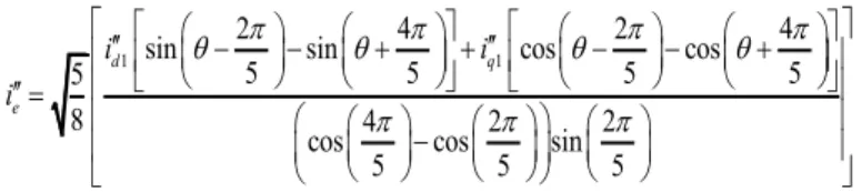
5 5 5 d q e i i i (38)
In the same way as the previous fault case, an optimization problem is solved for each speed to determine the torque-speed characteristics. In this optimization problem the maximal voltage and currents constraints are defined as previously:
max max I i i ib , , d e I (39) 2 d e b b s b b max d i i di v R i L M e V dt dt (40) 1 2 d e b d s d di di di d max v R i L M M e V dt dt dt (41) 1 2 e d b e s e di di di e max v R i L M M e V dt dt dt (42)
IV. CALCULATION RESULTS
In this section, optimizations have been carried out with the Matlab/Simulink environment by using fmincon function. The aim of these optimization processes is to determine the maximum torque characteristics of the machine/converter set following the method described in the previous section for each mode (healthy and fault modes). The optimization processes
allows to calculate the (id1, iq1) references of current and the corresponding torque and power
for each rotating speed of each mode. Currents id3, iq3 which in fault cases are not constant,
can be deduced from the knowledge of (id1, iq1). These current references can be stored in
look-up tables and used in the control scheme presented in Fig. 2. The machine parameters used in simulation and experimentation are reported in Tab. I
Fig. 3 presents the maximal torque and power V.S. the rotating speed for the studied cases. The results have been obtained with the parameters of the considered machine, a DC-bus
15
voltage VDC=30V and a maximum peak current IMAX=60A. These parameters correspond to
an experimental test bench located in our laboratory developed for mild-hybrid low voltage automotive application.
As mentioned in the introduction, the back-EMF of the PMSM machine are considered to be perfectly sinusoidal. As a consequence, the torque is only created by the currents in the
(d1q1) frame. However, the currents in (d3q3) frame are not null and not constant for the
faulted modes with the previously presented hypotheses (in healthy mode, these currents are controlled to be null).
Currents in (d3q3) frame can be calculated from the knowledge of id1 and iq1 (and of course
from the time values of the currents in the healthy phases).
As example, Fig 4 shows the id3 and iq3 current waveforms in case of 2 adjacent phases
opened.
V. EXPERIMENTAL RESULTS
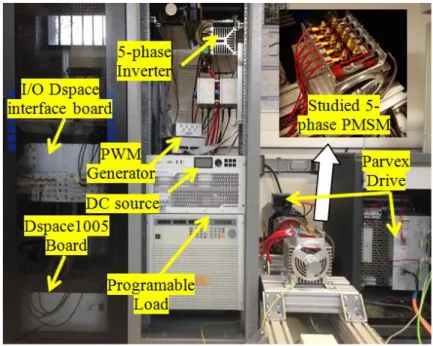
Some experimental tests have been carried out to validate the proposed approach. Fig. 5 gives the details of the test-bench. The tested five-phase machine is associated in the same shaft with an industrial 5kW 3-phase PMSM controlled by an industrial drive (“Parvex” drive). This industrial drive allows to control the speed of the two PMSM. In the experimental cases, the 3-phase PMSM is used as a motor and the 5-phase PMSM as a generator. The studied 5-phase PMSM is associated with a 5-phase PWM IGBT bridge. its switching frequency is set to 10 KHz. A dSPACE1005 board is used for controling this converter. This DSP system uses the current references calculated previously by the process described in sections III and IV. An I/O interface board is used for data acquisition and delivering the PWM signals to the IGBT drivers. The DC bus of this converter is generated by a diode rectifier connected in the AC grid. This is why a programmable electric load is connected in
16 parallel with the DC-bus to absorb the generated power provided by the 5- phase machine in order to keep the DC bus voltage constant.
Open-circuit faults are created by directly disconnecting the phases. In this work, the faults are created in a voluntary way and fault detection system is not implemented in the converter. Fig. 6 gives the experimental result in terms of torque-speed and power-speed characteristics for the healthy and faulted cases. These results are in good accordance with the results of
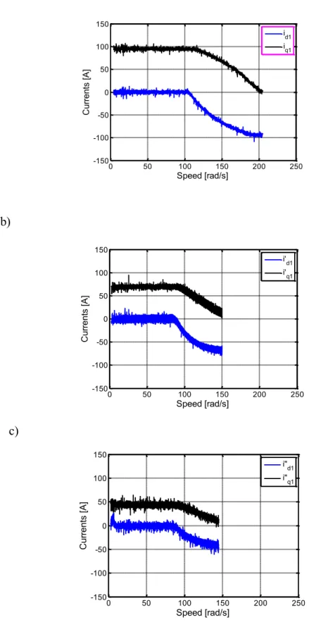
section IV and allow to validate the developed theory. Fig. 7 show the currents in the (d1q1)
frame. These results which correspond to the previously presented control strategy for each mode are in good accordance with the theoretical ones. In each case of Fig. 6 , the torque is
maximum below the base-speed by setting the current id1 to zero.
At these low speeds the maximal value of iq1 (and so the maximal torque)
corresponding to each mode is reached.
At the base-speed the maximum voltage is also reached. Beyond the base speed, flux
weakening operation begins by controlling a negative value of id1 leading to a decrease of iq1
to satisfy the maximum current constraint. As a consequence, a reduction of the torque is observed. It is obvious that the obtained torque value in fault mode is lower than the one in healthy mode due to the loss of a part of power related to opened phases. The maximum torque (20 N.m) is obtained in healthy mode. When one phase is opened, about 25% of power/torque is lost at low speed. If two non-adjacent phases are opened, the maximum torque value is about 9 N.m (less than half of the healthy torque) and then, if the two phases are adjacent, the low speed torque value is about 5.5 N.m (about a quarter of the healthy torque). It can also be observed that the capability of the drive in terms of speed range is strongly reduced when the machine is in fault.
The maximum speed which can be reached in healthy mode is around 200 rad/s. This maximal speed is only 150 rad/s for one phase open-circuited and for two non-adjacent phases
17 open-circuited and it is only 110 rad/s for two-adjacent phases open-circuited of the Park transformation.
Fig. 8 shows the phase currents in the particular case of two non-adjacent open-circuited phases. It can be noticed that as expected in theory, the phase currents respect the maximum
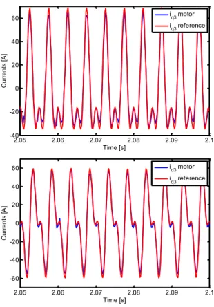
current constraint (Imax = 60A). The dq-3 currents are shown in Fig. 9. It can be noticed that PI
controllers used during experimentation give a sufficient performance. However, the current error could be improved by using more powerful controllers as sliding mode or neuro-fuzzy type or hysteresis current controller could be considered as a simple solution.
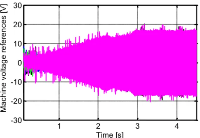
Fig. 10 and Fig. 11 show the voltage waveforms of the machine in healthy mode and with 2 non-adjacent phases opened. It has been shown that the voltage constraint is verified. For others faulty modes, the results are also satisfied.
VI. CONCLUSION
This paper presents a variable speed control strategy of a 5-phase PMSM with sinusoidal back-EMF in healthy mode and in 3 fault modes (which deal with open phases ) by taking into account the limit imposed by voltage and current maximum peak values. The presented strategy includes flux weakening operations in healthy and fault modes. The presented methodology makes possible to calculate the current references and the corresponding maximal torque versus speed characteristics by using an optimization process. These control strategies are implemented in an experimental test bench. The experimental results allow to validate the proposed approach The results show that a 5-phase PMSM is able to operate in fault modes while maintaining relatively good performances in a large range of speed if the machine design is adapted. Indeed The behavior of the machine and drive is directly related to the back-EMF harmonics contents and to the inductance values of the machine. This variable speed capability is particularly suitable for some applications such as electrical transportation
18 and renewable energy harvesting where a high reliability is required in a large range of speed. Finally the proposed control appears simple and efficient and is able to be used successfully in a large range of speed in helathy and faulted mode.
REFERENCES
[1] H. Jin, K. Min, Y. Jia-qiang, J. Hai-bo, and L. Dong, "Multiphase machine theory and its applications," in International Conference on Electrical Machines and Systems,
ICEMS. , 2008, pp. 1-7.
[2] E. Levi, "Multiphase Electric Machines for Variable-Speed Applications," IEEE
Transactions on Industrial Electronics, vol. 55, pp. 1893-1909, 2008.
[3] S. Dwari and L. Parsa, "An Optimal Control Technique for Multiphase PM Machines Under Open-Circuit Faults," IEEE Transactions on Industrial Electronics, vol. 55, pp. 1988-1995, 2008.
[4] S. Dwari and L. Parsa, "Fault-Tolerant Control of Five-Phase Permanent-Magnet Motors With Trapezoidal Back EMF," IEEE Transactions on Industrial Electronics, vol. 58, pp. 476-485, 2011.
[5] X. Kestelyn and E. Semail, "A Vectorial Approach for Generation of Optimal Current References for Multiphase Permanent-Magnet Synchronous Machines in Real Time,"
IEEE Transactions on Industrial Electronics, vol. 58, pp. 5057-5065, 2011.
[6] F. Locment, E. Semail, and X. Kestelyn, "Vectorial Approach-Based Control of a Seven-Phase Axial Flux Machine Designed for Fault Operation," IEEE Transactions on
Industrial Electronics, vol. 55, pp. 3682-3691, Oct 2008.
[7] N. K. Nguyen, D. Flieller, X. Kestelyn, and E. Semail, "Analytical Optimal Currents for Multiphase PMSMs Under Fault Conditions and Saturation," presented at the International conference on Industrial Electronics IECON Dallas, TX-USA, 2014. [8] D. Flieller, N. K. Nguyen, P. Wira, G. Sturtzer, D. O. Abdeslam, and J. Merckle, "A
19 Self-Learning Solution for Torque Ripple Reduction for Nonsinusoidal Permanent-Magnet Motor Drives Based on Artificial Neural Networks," Industrial Electronics,
IEEE Transactions on, vol. 61, pp. 655-666, 2014.
[9] A. Mohammadpour and L. Parsa, "A Unified Fault-Tolerant Current Control Approach for Five-Phase PM Motors with Trapezoidal Back EMF under Different Stator Winding Connections," IEEE Transactions on Power Electronics, vol. 28, pp. 3517 - 3527 July 2013 2013.
[10] F. Jen-Ren and T. A. Lipo, "Disturbance-free operation of a multiphase current-regulated motor drive with an opened phase," Industry Applications, IEEE Transactions
on, vol. 30, pp. 1267-1274, 1994.
[11] H. A. Toliyat, "Analysis and simulation of five-phase variable-speed induction motor drives under asymmetrical connections," Power Electronics, IEEE Transactions on, vol. 13, pp. 748-756, 1998.
[12] L. Parsa and H. A. Toliyat, "Fault-tolerant five-phase permanent magnet motor drives," in Industry Applications Conference, 2004. 39th IAS Annual Meeting. Conference
Record of the 2004 IEEE, 2004, pp. 1048-1054 vol.2.
[13] A. El-Refaie, "Fractional-slot concentrated-windings: A paradigm shift in electrical machines," in Electrical Machines Design Control and Diagnosis (WEMDCD), 2013
IEEE Workshop on, 2013, pp. 24-32.
[14] L. Li, B. Aslan, L. Kobylanski, P. Sandulescu, F. Meinguet, X. Kestelyn, and E. Semail, "Computation of optimal current references for flux-weakening of multi-phase synchronous machines," in IECON 2012 - 38th Annual Conference on IEEE Industrial
Electronics Society, 2012, pp. 3610-3615.
[15] L. Parsa, N. Kim, and H. A. Toliyat, "Field Weakening Operation of High Torque Density Five-Phase Permanent Magnet Motor Drives," in Electric Machines and
20
Drives, 2005 IEEE International Conference on, 2005, pp. 1507-1512.
[16] A.-P. Sandulescu, F. Meinguet, X. Kestelyn, E. Semail, and A. Bruyère, "Flux-weakening operation of open-end winding drive integrating a cost effective high-power charger," IET Electrical Systems in Transportation, vol. 3, pp. 20-21, 2013.
[17] X. Song, X. Wen, and W. Cong, "Research on field-weakening control of multiphase permanent magnet synchronous motor," in Electrical Machines and Systems (ICEMS),
2011 International Conference on, 2011, pp. 1-5.
[18] L. Lu, E. Semail, L. Kobylanski, and X. Kestelyn, "Flux-Weakening Strategies for a Five-Phase PM Synchronous Machine," Proceedings of the 2011-14th European
Conference on Power Electronics and Applications (EPE 2011), pp. 1-7, 2011.
[19] S. Zhigang, W. Jiabin, G. W. Jewell, and D. Howe, "Enhanced Optimal Torque Control of Fault-Tolerant PM Machine Under Flux-Weakening Operation," IEEE Transactions
on Industrial Electronics, vol. 57, pp. 344-353, 2010.
[20] X. Kestelyn, E. Semail, and J. Hautier, "Vectorial multi-machine modeling for a five-phase machine," International Congress on Electrical Machines (ICEM’02), 2002. [21] L. Parsa and H. A. Toliyat, "Five-phase permanent-magnet motor drives," Industry
Applications, IEEE Transactions on, vol. 41, pp. 30-37, 2005.
[22] E. Semail, A. Bouscayrol, and J. P. Hautier, "Vectorial formalism for analysis and design of polyphase synchronous machines," European Physical Journal-Applied
Physics, vol. 22, pp. 207-220, Jun 2003.
[23] E. Levi, I. N. W. Satiawan, N. Bodo, and M. Jones, "A Space-Vector Modulation Scheme for Multilevel Open-End Winding Five-Phase Drives," Energy Conversion,
21
List of tables
Tab.I. Electricals parameters of the converter-machine
List of figures
1. Fig. 1. Power circuit configuration of the 5-phase PMSM system 2. Fig. 2. Proposed control scheme
3. Fig. 3. Optimization results: Comparison of healthy mode and faults modes. (a) Torque-speed characteristics. (b) Power-speed characteristics.
4. Fig. 4. Currents in dq-3 frame at 857 rpm in case of 2 adjacent opened phases in MTPA-s control.
5. Fig. 5. Experimental test-bed.
6. Fig. 6. (Experimental result) Comparison of experimental results of healthy mode and faults modes. (a) Torque/Speed characteristic. (b) Power/Speed characteristic.
7. Fig. 7. (Experimental result) Currents in (d1q1) frame VS speed (from measured phase
currents). (a) Healthy mode. (b) 1 phase opened. (c) 2 non-adjacent phases opened. (d) 2 adjacent phases opened.
8. Fig. 8. (Experimental result) Reference and measured phase currents at 857 rpm. with 2 non-adjacent phases opened.
9. Fig. 9. (Experimental result) Reference and measured dq-3 currents at 857 rpm with 2 non-adjacent phases opened.
10. Fig. 10. (Experimental result) Voltage waveform references in healthy mode.
11. Fig. 11. (Experimental result) Voltage waveform references with 2 non-adjacent phases opened.
22
.
Fig. 1. Power circuit configuration of the 5-phase PMSM system
Fig. 2. Proposed control scheme
Look-up Tables Park + PI dq current controllers id1q1d3q3* vabcde* d/dt 5-phase VSI + PWM 5-phase PMSM ibcde 5 4 4 load Fault information VDC Optimization (fmincon) machine parameters and id1q1d3q3* Premilinary calculation Imax Vmax Ω Ω θ
23 Fig. 3. Optimization results: Comparison of healthy mode and faults modes. (a) Torque-speed
characteristics. (b) Power-speed characteristics.
Fig. 4. Currents in dq-3 frame at 857 rpm in case of 2 adjacent opened phases in MTPA-s control 0 50 100 150 200 -5 0 5 10 15 20 25 Speed [rad/s] To rq ue [N .m ] Healthy Two adjacent phases open-circuited Phase-a open-circuited Two non-adjacent phases open-circuited 0 50 100 150 200 -500 0 500 1000 1500 2000 2500 Speed [rad/s] P ow er [w ] Healthy Phase-a open-circuited
Two non-adjacent phases open-circuited two-adjacent phases open-circuited -0.01 -0.005 0 0.005 0.01 -80 -60 -40 -20 0 20 40 60 80 Time (s) C ur re nt s (A ) I"d3 I"q3 a) b)
24 Fig. 5. Experimental test-bed.
0 50 100 150 200 250 -5 0 5 10 15 20 25 Speed [rad/s] To rq ue [N m ] two-adjacent phases open-circuited Phase-a Healthy
Two non-adjacent phases open-circuited 0 50 100 150 200 250 -500 0 500 1000 1500 2000 2500 3000 Speed [rad/s] P ow er [W ] Healthy Phase-a two-adjacent phases
open-circuited Two non-adjacent phases open-circuited
b) a)
25 Fig. 6. (Experimental result) Comparison of experimental results of healthy mode and faults
modes. (a) Torque/Speed characteristic. (b) Power/Speed characteristic.
0 50 100 150 200 250 -150 -100 -50 0 50 100 150 C ur re nt s [A ] Speed [rad/s] id1 iq1 0 50 100 150 200 250 -150 -100 -50 0 50 100 150 Speed [rad/s] C ur re nt s [A ] i'd1 i'q1 0 50 100 150 200 250 -150 -100 -50 0 50 100 150 Speed [rad/s] C ur re nt s [A ] i"d1 i"q1 a) b) b) c) d) a)
26
Fig. 7. (Experimental result) Currents in (d1q1) frame VS speed (from measured phase
currents). (a) Healthy mode. (b) 1 phase opened. (c) 2 non-adjacent phases opened. (d) 2 adjacent phases opened.
Fig. 8. (Experimental result) Reference and measured phase currents at 857 rpm. with 2 non-adjacent phases opened.
0 50 100 150 200 250 -150 -100 -50 0 50 100 150 Speed [rad/s] C ur re nt s [A ] i"d1 i"q1 2.05 2.06 2.07 2.08 2.09 2.1 -60 -40 -20 0 20 40 60 Time [s] P ha se c ur re nt s [A ]
27 Fig. 9. (Experimental result) Reference and measured dq-3 currents at 857 rpm with 2
non-adjacent phases opened.
Fig. 10. (Experimental result) Voltage waveform references in healthy mode.
2.05 2.06 2.07 2.08 2.09 2.1 -40 -20 0 20 40 60 Time [s] C ur re nt s [A ] iq3 motor iq3 reference 2.05 2.06 2.07 2.08 2.09 2.1 -60 -40 -20 0 20 40 60 Time [s] C ur re nt s [A ] id3 motor iq3 reference 1 2 3 4 -30 -20 -10 0 10 20 30 Time [s] M ac hi ne v ol ta ge s [V ]
28 Fig. 11. (Experimental result) Voltage waveform references with 2 non-adjacent phases
opened. TABLE I
ELECTRICALS PARAMETERS OF THE CONVERTER-MACHINE
Electrical parameters Value
Stator resistance Rs = 9.1 mΩ Phase inductance L = 0.09 mH Mutual inductance 1 M1 = 0.02 mH Mutual inductance 2 M2 = -0.01 mH Ld1 = Lq1 0,12 mH Ld3 = Lq3 0.04 mH Magnet flux 1 19.4 mWb
Pole pairs number p = 7
1 2 3 4 -30 -20 -10 0 10 20 30 Time [s] M ac hi ne v ol ta ge re fe re nc es [V ]
29
DC-bus voltage VDC = 30V