Science Arts & Métiers (SAM)
is an open access repository that collects the work of Arts et Métiers Institute of
Technology researchers and makes it freely available over the web where possible.
This is an author-deposited version published in: https://sam.ensam.eu Handle ID: .http://hdl.handle.net/10985/9897
To cite this version :
Anne BOMONT-ARZUR, Pascal BUESSLER, Olivier BOMONT, Christophe LESCALIER - High Strength Steel solutions for powertrain applications - In: 4th International Conference on Steels in Cars and Trucks, Allemagne, 2014-06-15 - Future trends in steel development, processing technology and applications bringing the automotive, supplier and steel industries together - 2014
High Stength Steel solutions for powertrain applications :
Machinability testing for gear hobbing applications
Anne Bomont Arzur1, Pascal Buessler1, Olivier Bomont2, Christophe Lescalier2
1ArcelorMittal Long Product R&D - Europe R & D, 57 360 Amnéville, France
2 LEM3, ENSAM, 57000 Metz, France
[email protected] Abstract
ArcelorMittal focuses on both mechanical performances and machinability while designing new steel grades. ArcelorMittal has developed specific programs for machinability testing in turning, low and high speed drilling and gear machining. Machinability is evaluated through cutting forces, chip shape, surface quality and tool life. Gear machining is one of the main machining operations involved in powertrain manufacturing operations. The literature proposes many papers dealing with this process however there are too few studies interested in steel machinability evaluation while gear machining. This paper focuses on a particular gear manufacturing process, i.e. gear hobbing, and more precisely on steel machinability for gear hobbing applications. Tools as well as kinematics of gear hobbing are quite complex. This paper proposes a comprehensive experimental protocol for machinability testing. This protocol is based on a European standard. Tests are performed on a machine tool using a commercially available cutting tool. Tests provide the range of cutting conditions for five different steel grades. Both steels have a ferrite-pearlite structure with yield stress from 530 to 800 MPa and ultimate tensile stress from 680 to 900 MPa. Four grades are devoted to bar machining. The last one is devoted to forming and then machining operations. Many metallurgical solutions are investigated to enhance machinability such as lead addition or increase in sulfur content or calcium treatment. This paper analyses the influence of steel composition and structure on machinability. It shows the relevance of metallurgical solutions for machinability enhancement even for powertrain applications. Cutting conditions clearly depend on the metallurgical solution even if specific cutting force is finally close. The main difference is found on tool wear with tool life ratio from 1 to 1.5.
Keywords: Engineering steels, machinability, gear hobbing, the Couple Tool-Material.
1. Introduction
The gear hobbing process investigations started due to a ArcelorMittal customer assistance request. Literature proposes numerous studies devoted to gear hobbing. Most of them are concerned with hobbing modelling (chip section and/or tool wear and/or cutting forces prediction) or hobbing testing (i.e. wear distribution along the cutting edges and/or performance evaluation for substrate or coating or edge preparation) [1] [2] [3] [4] [5]. One of the main difficulties in gear manufacturing studies is that gear cutting machines are production machines where classical instrumentation is difficult to implement. Several authors have proposed relevant techniques to perform hobbing or hobbing-like operations. The experiments performed are so called fly hobbing, a technique widely used by researchers [1] [2] [4] [6] [7].
Few papers are dealing with the influence of metallurgical solution on machinability in gear hobbing. ArcelorMittal develops a research program focusing on the influence of metallurgical solution on machinability within a whole manufacturing process involving both forging and/or heat treatment [8]. Many machining processes have already been investigated: turning, drilling, gun drilling [8] [9] [10]. This paper proposes results concerned with hobbing.
2. Steel grades investigated
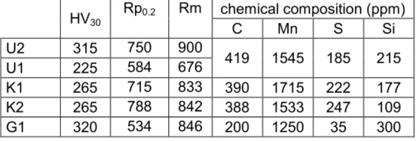
Machinability is investigated for five low alloy steel grades devoted to powertrain applications. The steel grades investigated are called G1, U1, U2, K1 and K2. Their chemical composition and mechanical properties are listed in the Table 1.G1 is a steel grade commonly used for automotive gear applications. U1, U2, K1 and K2 are steel grades used in swiss machining applications. The steel grade U is available with two different structures. U2 is cold drawn. A partial spheroidization heat treatment is applied to U1 before cold drawing. K1 and K2 global chemical composition are very close. A machinability enhancement treatment using both metallic and non-metallic inclusions is applied to K2.
HV30 Rp0.2 Rm chemical composition (ppm) C Mn S Si U2 315 750 900 419 1545 185 215 U1 225 584 676 K1 265 715 833 390 1715 222 177 K2 265 788 842 388 1533 247 109 G1 320 534 846 200 1250 35 300
1. Introduction
The gear hobbing process investigations started due to a ArcelorMittal customer assistance request. Literature proposes numerous studies devoted to gear hobbing. Most of them are concerned with hobbing modelling (chip section and/or tool wear and/or cutting forces prediction) or hobbing testing (i.e. wear distribution along the cutting edges and/or performance evaluation for substrate or coating or edge preparation) [1] [2] [3] [4] [5]. One of the main difficulties in gear manufacturing studies is that gear cutting machines are production machines where classical instrumentation is difficult to implement. Several authors have proposed relevant techniques to perform hobbing or hobbing-like operations. The experiments performed are so called fly hobbing, a technique widely used by researchers [1] [2] [4] [6] [7].
Few papers are dealing with the influence of metallurgical solution on machinability in gear hobbing. ArcelorMittal develops a research program focusing on the influence of metallurgical solution on machinability within a whole manufacturing process involving both forging and/or heat treatment [8]. Many machining processes have already been investigated: turning, drilling, gun drilling [8] [9] [10]. This paper proposes results concerned with hobbing.
2. Steel grades investigated
Machinability is investigated for five low alloy steel grades devoted to powertrain applications. The steel grades investigated are called G1, U1, U2, K1 and K2. Their chemical composition and mechanical properties are listed in the Table 1.G1 is a steel grade commonly used for automotive gear applications. U1, U2, K1 and K2 are steel grades used in swiss machining applications. The steel grade U is available with two different structures. U2 is cold drawn. A partial spheroidization heat treatment is applied to U1 before cold drawing. K1 and K2 global chemical composition are very close. A machinability enhancement treatment using both metallic and non-metallic inclusions is applied to K2.
HV30 Rp0.2 Rm chemical composition (ppm) C Mn S Si U2 315 750 900 419 1545 185 215 U1 225 584 676 K1 265 715 833 390 1715 222 177 K2 265 788 842 388 1533 247 109 G1 320 534 846 200 1250 35 300
3. Machinability evaluation
Machinability is evaluated based on experiments led according to the Couple Tool Material methodology [11]. It is a standardized experimental protocol devoted to evaluate machinability in turning, milling and drilling. The experiments are to be done for each association workpiece / cutting tool / machining operation. The result is an operating range i.e. the whole acceptable machining conditions for the association workpiece / tool / operation. A machining condition is regarded as acceptable when:
• specific energy values are acceptable,
• chips are regular and fragmented,
• tool wear is regular and controllable,
• surface roughness is compatible with other similar machining applications,
The Couple Tool Material standard proposes to measure the specific energy and to determine the operating range from its variations versus either the cutting speed or the feed. Specific energy measurement is not relevant for fly hobbing experiments. The contact time between cutting edge and workpiece is very low (between 5 and 100 ms depending on the cutting conditions). The most convenient system for this purpose is the piezoelectric dynamometer. The operating range is also determined not from specific energy but from a very close physical quantity: the specific cutting
force kC. An usual value of feed per tooth is arbitrarily chosen. The cutting speed
varies within a large range (about from 10 to 250 m/min).
kC clearly depends on chip thickness however a curve kC = f(Vc) can be drawn for
a particular chip thickness value, and Vcmin can be deduced. Specific energy as
well as specific cutting force usually decreases when cutting speed increases. An
asymptotic trend often appears when drawing the curve kC = f(Vc). Vcmin is
considered as the minimal cutting speed value required getting low and constant
values of kC.
On one insert engagement, the specific cutting speed can be drawn as a function of the chip thickness which is linked to the feed. That involves the possibility to
determine the minimum feed fmin without doing tests with various feed (such as the
determination of Vcmin).
Physical phenomena in tool wear lead to an alteration of the tool geometry [13], and then the machined parts geometry is perturbed. Standard details how to characterize this geometry damages on both the relief and rake face. The steel grades machinability can be compared by many ways such as the tool life (T) until a VB value about 200 µm is reached. Three cutting speeds from the operating range are arbitrarily chosen for the wear tests of each steel grade and the lengths hobbed are computed. Taylor equation is simplified, the cutting speed being the predominant factor, the influence of the feed has not been considered.
4. Experimental device
Fly hobbing operations are performed on a 4-axis NC machining centre Ernault FH 45. Forces are measured using a Kistler 9257 3 component dynamometer. The tool is a Sandvik side milling cutter with indexable inserts. The outer diameter is 80 mm. The width is 5 mm. One GC4040 or GC4240 coated carbide insert is used for fly hobbing tests. It enables to reduce workmaterial quantity for tool wear tests. It also simplifies cutting forces analysis and insures a regular tool wear.
5. Experiments and results
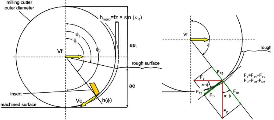
Milling kinematics is quite complex. The cutting edge trajectory (i.e. a cycloid) leads to a continuous variation in cutting geometry and instantaneous chip thickness. Edge geometry variations are not considered in the analysis of cutting forces. Chip thickness is approximated using:
( )
φ fz sin( )
φ sin( )
κ fz sin( )
φh = × × R = × with cos 11 2 ae ,
D
φ
∈π
− − − × π
(3)
All experiments consist in down milling operations. Down milling is commonly used during roughing operations.
φφ1 φ2 ae Vc Vf hmaxi=fz × sin (κR) h(φ) milling cutter outer diameter insert aei machined surface rough surface φφ1 φ2 ae Vc Vf hmaxi=fz × sin (κR) h(φ) milling cutter outer diameter insert aei machined surface rough surface φ Vf rough FZ FY FR1 FR2 FT1 FT2 π−φ π−φ FT=FT1+FT2 FR=FR1-FR2 φ Vf rough FZ FY FR1 FR2 FT1 FT2 π−φ π−φ FT=FT1+FT2 FR=FR1-FR2
Figure 1 : Milling kinematics - Chip thickness
Cutting forces values FX, FY, FZ are computed to get the tangential and radial
forces, respectively FT and FR. FX and so axial force are still negligible due to the
tool geometry (inclination angle is zero). Cutting forces time curves and the cutting insert angular position are fitted thanks to a FFT analysis. It provides both the actual rotating speed of the spindle and the phase shift between tool angular position and time. The cutting tool geometry is extremely simple and prevents cutting force discretization along cutting edge. Models provided are mechanistic [12] :
( )
k h( )
ap4. Experimental device
Fly hobbing operations are performed on a 4-axis NC machining centre Ernault FH 45. Forces are measured using a Kistler 9257 3 component dynamometer. The tool is a Sandvik side milling cutter with indexable inserts. The outer diameter is 80 mm. The width is 5 mm. One GC4040 or GC4240 coated carbide insert is used for fly hobbing tests. It enables to reduce workmaterial quantity for tool wear tests. It also simplifies cutting forces analysis and insures a regular tool wear.
5. Experiments and results
Milling kinematics is quite complex. The cutting edge trajectory (i.e. a cycloid) leads to a continuous variation in cutting geometry and instantaneous chip thickness. Edge geometry variations are not considered in the analysis of cutting forces. Chip thickness is approximated using:
( )
φ fz sin( )
φ sin( )
κ fz sin( )
φh = × × R = × with cos 11 2 ae ,
D
φ
∈π
− − − × π
(3)
All experiments consist in down milling operations. Down milling is commonly used during roughing operations.
φφ1 φ2 ae Vc Vf hmaxi=fz × sin (κR) h(φ) milling cutter outer diameter insert aei machined surface rough surface φφ1 φ2 ae Vc Vf hmaxi=fz × sin (κR) h(φ) milling cutter outer diameter insert aei machined surface rough surface φ Vf rough FZ FY FR1 FR2 FT1 FT2 π−φ π−φ FT=FT1+FT2 FR=FR1-FR2 φ Vf rough FZ FY FR1 FR2 FT1 FT2 π−φ π−φ FT=FT1+FT2 FR=FR1-FR2
Figure 1 : Milling kinematics - Chip thickness
Cutting forces values FX, FY, FZ are computed to get the tangential and radial
forces, respectively FT and FR. FX and so axial force are still negligible due to the
tool geometry (inclination angle is zero). Cutting forces time curves and the cutting insert angular position are fitted thanks to a FFT analysis. It provides both the actual rotating speed of the spindle and the phase shift between tool angular position and time. The cutting tool geometry is extremely simple and prevents cutting force discretization along cutting edge. Models provided are mechanistic [12] :
( )
k h( )
apkC and kR simple models are used to
( )
ref( )
nC ref C C k hh k × = φ φ( )
ref( )
nR ref R R k hh k × = φ φ (7)kCref nC kRref nR are determined for each experiments from cutting forces curves
using a least square method. ap is constant for the whole experiments and is equal to the tool width.
0.00 0.04 0.08 0.12 0.16 0.20 -2000 -1200 -400 400 1200 2000 125 140 155 170 185 200 chi p t hi ck ne ss h( φ) (m m ) m eas ur ed c ut ting for ces (N )
cutting edge angular position φ (°) 0.00 0.04 0.08 0.12 0.16 0.20 -2000 -1200 -400 400 1200 2000 125 140 155 170 185 200 chi p t hi ck ne ss h( φ) (m m ) cut ting f or ce s F T and F R (N ) angular position φ (°)
Figure 2: Forces measurements and chip thickness
(G1 steel grade, VC = 150 m/min, f = 0.2 mm/rev)
For variable cutting speed value, kC computations lead to graphs such as :
0 1200 2400 3600 4800 6000 0 60 120 180 240 300 kC ref (M Pa ) -href = 1 m m VC(m/min) 0.00 1.50 3.00 4.50 6.00 7.50 0 60 120 180 240 300 R a (µm ) VC(m/min)
Figure 3: Vcmin determined from kC computations and Ra measurements
(G1 steel grade, f = 0.2 mm/rev)
Roughness is one of the most important specifications on gear surfaces. Roughness levels depend on the gear’s precision class. The longitudinal roughness in the groove is then measured. When machining with a constant feed, the roughness is supposed to remain almost constant. Measurements highlight that roughness depends on cutting speed value and decreases with an increase of
cutting speed. A specific cutting speed value, i.e. Vcmin or minimal cutting speed,
should be defined based on roughness or specific cutting force considerations. A synthesis for both steel grades is presented in Table 2.
A mean apparent friction coefficient is calculated within the chip thickness range
used to determine kCref value.
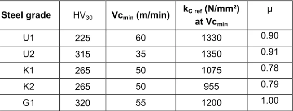
Steel grade HV30 Vcmin (m/min) kC refat Vc (N/mm²) min µ U1 225 60 1330 0.90 U2 315 35 1350 0.91 K1 265 50 1075 0.78 K2 265 50 955 0.79 G1 320 55 1200 1.00
Table 2 : Synthetic table of the values Vcmin and µ
Minimum cutting speeds are almost equivalent for both steel grades and are extremely low compared with cutting speed values recommended by cutting tools manufacturers. The decrease in hardness due to the U2 heat treatment tends to
increase Vcmin.
Specific cutting pressures as well as apparent friction coefficient are significantly lower for both K steel grades. K2 induces a lower specific pressure than K1. K2 machinability is metallurgicaly improved using specific inclusions.
Specific cutting pressures are similar for U1 and U2 despite heat treatment. Even if specific cutting pressures are similar for U1, U2 and G1, tool chip contact seems more severe when machining G1. U1 and U2 machinability has been enhanced using specific non metallic inclusions unlike G1. These results should be correlated with tool wear tests before proposing a reliable machinability ranking.
6. Tool wear tests
Tool wear tests are based on standardized protocols [14]. Tool wear tests are also performed with a single insert on the milling cutter. Pictures are taken along the tool life and VB is measured from time to time. Tool wear criterion choice is based on several tool wear curves. The maximum value allowed is VB = 200 µm.
The whole wear curves show a running in of the tool. The tool wear rate is slow until the tool coating is removed. When the tool substrate is in contact with the material machined, global tool wear rate significantly increases and some cracks appear across cutting edge. They are assumed to be related to oxidation wear process.
Tool life is evaluated based on a Taylor simplified model i.e. Vc⋅Tn=C. Tool life
model coefficients are determined through least square analysis. The model perfectly fits to experimental data. Even if two tests only are required to estimate the Taylor model coefficient, the investigations are done with at least three cutting speeds to improve precision.
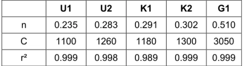
U1 U2 K1 K2 G1
n 0.235 0.283 0.291 0.302 0.510
C 1100 1260 1180 1300 3050
r² 0.999 0.998 0.989 0.999 0.999
Table 3 : Taylor coefficients (f= 0.2 mm/rev, tool life criterion VB = 200 µm) Correlation coefficients are pretty high for both steels grade. A major difference should be observed for G1 steel grade since C and n are higher. Tool life should decrease faster when increasing cutting speed. Tool lives about 400 and even 600 min have been measured for U and K steel grades. The higher tool life encountered for G1 is only about 200 min. Cutting speed range should then be narrower for G1. The following graphs synthesize tool wear tests for the steel grades.
200 250 300 350 400 450 100 160 220 280 340 400 Vc (m /m in ) Steel hardness (HB) U1 U2 K1 K2 G1 200 250 300 350 400 450 100 160 220 280 340 400 Vc (m /m in ) Steel hardness (HB) U1 U2 K1 K2 G1 T = 200min T = 60 min
Figure 4: Tool life comparison graph
(f = 0.2 mm/rev, tool life criterion VB = 200 µm)
Cutting speeds are estimated for each steel grade and two tool lives (i.e. 60 and 200 m/min). Cutting speeds are ranked according to steel hardness. The higher the cutting speed is, the better the steel machinability is. There is an overall trend: when the hardness increases, the cutting speed decreases. A solid line shows it for many steels tested. However phenomena should occur at the tool / material interfaces, such as Built-Up Layer for instance, which tends to increase tool life in a more or less narrow cutting range. It is frequently observed when machining such steels. K steels machinability is similar when observing tool wear rate (for both high and low tool lives or respectively low and high cutting speeds). However U2 tool wear rate seems lower especially for low tool lives (i.e. higher cutting speeds). It may be explained as an occurrence of Built-Up Layers provided by non-metallic inclusions provided in this steel grade.
7. Conclusions
This paper proposes an application of the Couple Tool Material approach to gear hobbing operations. Cutting forces, surface quality, friction intensity and tool wear
are measured and enable to propose relevant operating range. Chip morphology analysis as well as allowed chip thickness ranges confirms the previous results. The protocol enables to rank five steel grades G, U and K specifically developed by ArcelorMittal for gear hobbing applications. Experimental results show the influence of machinability metallurgical enhancement especially at high cutting speeds. They show that U2 steel has a good behaviour in machining since its machining conditions can be chosen in a wide range. Concerning the tool wear tests, U2 is the one which wears the tool the less. K1 and K2 steels are the most wearer grades among the steels with improved machinability. However cutting forces as well as tool – chip contact severity are lower.
8. Acknowledgment
This experimental work was performed at Arts et Métiers ParisTech in Metz in partnership with ArcelorMittal. We thank Eric Grandgirard, Olivier Messerlin and Daniel Boehm for their involvement.
9. References
[1] Bouzakis, K.-D. et al., CIRP Annals, 676-696 (2008) 57-2. [2] Rech, J., Wear, 505–512 (2006), 261.
[3] Vicenzi, B. et al., International Journal of Refractory Metals and Hard Materials, 11-16 (2001) 19.
[4] Claudin, C., Rech J., Journal of Materials Processing Technology, 5152-5160 (2009) 209.
[5] Gerth, J. et al., Wear, 2257‑2268 (2009) 267.
[6] Klocke, F., Kuchle, A. “Manufacturing Processes - 1: Cutting”, Springer Verlag, 2013.
[7] Stein, S. et al., Procedia CIRP, 220-225 (2012) 1.
[8] Bomont, A et al., 5th International Conference on High Speed Machining, Metz, 39-50 (2006).
[9] Resiak, B, 33ème Congrès de Traitement Thermique et de l’Ingénierie des Surfaces, Reims, 37-48 (2005).
[10] Bomont, A et al. 5th International Conference on High Speed Machining, Metz, 2006, 151-164 (2006).
[11] AFNOR, NF E 66-520 (2000).
[12] Altintas, Y., “Manufacturing automation”, Cambridge University Press, 2000, [13] Le Maître, F. et al., Matériaux et Techniques, 5-14 (1999), 5-6.