HAL Id: tel-01219309
https://pastel.archives-ouvertes.fr/tel-01219309
Submitted on 22 Aug 2016HAL is a multi-disciplinary open access
archive for the deposit and dissemination of sci-entific research documents, whether they are pub-lished or not. The documents may come from teaching and research institutions in France or abroad, or from public or private research centers.
L’archive ouverte pluridisciplinaire HAL, est destinée au dépôt et à la diffusion de documents scientifiques de niveau recherche, publiés ou non, émanant des établissements d’enseignement et de recherche français ou étrangers, des laboratoires publics ou privés.
Experimental and numerical analysis of nonlinear
properties of rail fastening systems
Yan Liu
To cite this version:
Yan Liu. Experimental and numerical analysis of nonlinear properties of rail fastening systems. Materials. Université Paris-Est; Tongji university (Shanghai, Chine), 2015. English. �NNT : 2015PESC1059�. �tel-01219309�
THESE
Pour obtenir le grade de
Docteur de l
’Université Paris-Est
Discipline: Mécanique
Présentée par
Yan LIU
Experimental and numerical analysis of nonlinear properties of
rail fastening systems
JURY
Prof. Tianxing WU Rapporteur Shanghai Jiaotong University Prof. Qiang GUO Rapporteur Shanghai University Prof. Denis Duhamel Examinateur Ecole des Ponts ParisTech Prof. Rongying SHEN Examinateur Shanghai Jiaotong University Prof. Songliang LIAN Examinateur Tongji University SN ENGR Xun PENG Examinateur Jiangyin Haida Co., Ltd
Prof. Honoré YIN Directeur de thèse Ecole des Ponts ParisTech Prof. Yanyun LUO Co-Directeur de thèse Tongji University
Résumé
Le besoin en isolation vibratoire des voies ferrées conduit de plus en plus souvent au recours à des systèmes d'attache de rail souples avec des designs sophistiqués. Par contre, les produits deviennent diversifiés mais leur conception se fait de manière empirique dans la pratique. Dans ce travail de thèse, deux systèmes d'attache de rail sont étudiés expérimentalement et numériquement: un système qui travaille principalement en cisaillement et l'autre en compression. Des essais quasi-statiques et dynamiques sont menés puis les résultats sont analysés à l'aide de différents modèles mécaniques. En plus, une série de tests sur les élastomères utilisés dans les deux systèmes sont réalisés. Ces tests permettent de choisir des modèles hyperélastiques et viscoélastique appropriés, et de déterminer les paramètres de propriétés mécaniques des élastomères dans ces modèles par des simulations Abaqus. En utilisant également Abaqus, des analyses par élément fini des deux systèmes d'attache sont effectués et les résultats sont comparés aux ceux des essais. Des non-linéarités d'origine matérielle et géométrique sont ainsi analysées et expliquées. Enfin, des études de sensibilité des paramètres sont effectuées, suivies d'études d'optimisation structurale. Cet étude devrait être utile pour une meilleure compréhension du comportement mécanique des systèmes d'attache de rail sous chargement statique et dynamique, et au final pour une meilleure pratique dans la conception et l'optimisation des produits.
Mots clés: systèmes d'attache de rail, expérience et modèle de mathématique, FEA, sensibilité des paramètres, optimisation structurale
Abstract
Higher demand on vibration isolation of track structure in modern railway track leads to a trend of lower stiffness of rail fastening systems, places an increasing need for better design approach as well. However the current development status of rail fastening industry is dramatically diversified but mainly empirical. In this work, a shear type and a bonded compressed type of rail fastening systems are investigated experimentally and numerically. Quasi-static and dynamic experiments are carried out and the results are analysed with different mechanical models. Besides, a series of fundamental rubber material tests is performed to accurately describe the rubber material used in the two fastening systems. The most appropriate hyperelastic and hysteresis models are chosen with the help of simulations by Abaqus. Also by using Abaqus, finite element analyses are conducted for the two fastening systems and the numerical results are compared with those of experiments. Material and geometrical nonlinear features observed in the measured displacement-force curves are analysed and explained. Finally, parameter sensitivity of the two fastening specimens is studied, followed by an optimization process to meet practical optimization objectives. The present work is believed to be helpful for understanding the mechanical behaviour of rail fastening systems, while enlightening the engineering practice, and eventually improving product designing and optimizing measures.
Key words: Rail fastening systems, nonlinear properties, numerical modelling, FEA, parameter sensitivity analysing, structural optimization
TABLE OF CONTENTS
ABSTRACT ... I ACKNOWLEDGMENTS ... IV LIST OF ILLUSTRATIONS ... VI LIST OF TABLES ... IX
Chapter 1 Research background ... 1
1.1 Track structure ... 1
1.1.1 Ballasted track structure ... 1
1.1.2 Slab track ... 5
1.2 Basic concept of vibration isolation ... 12
1.3 Research situation of rail fastening systems ... 14
1.3.1 Current situation of product development ... 14
1.3.2 Theoretical study situation ... 15
1.4 Scope of the present research ... 24
Chapter 2 Experiment of rail fastening systems ... 26
2.1 Introduction ... 26
2.2 Test apparatus and specimens ... 27
2.2.1 Test apparatus ... 27
2.2.2 Specimens ... 27
2.3 Test operating conditions ... 30
2.3.1 Quasi-static loading ... 30
2.3.2 Dynamic loading ... 34
2.4 Testing results and analysing ... 36
2.4.1 Quasi-static test ... 36
2.4.2 Dynamic test ... 37
2.5 Summary ... 46
Chapter 3 Modelling of the rail fastening systems ... 48
3.1 Introduction ... 48
3.2 Presented model I ... 51
3.2.1 Modelling ... 52
3.2.2 Determination of model parameters ... 54
3.3 Presented model II ... 58
3.3.1 Modelling ... 59
3.3.2 Determination of model parameters ... 62
3.4 Presented model III ... 67
3.4.1 Modelling ... 67
3.4.2 Determination of model parameters ... 73
3.5 Summary ... 77
Chapter 4 Fundamental rubber material tests and simulation ... 79
4.1 Introduction ... 79
4.2 Test details and results ... 80
4.2.1 Specimens preparation and test apparatus ... 80
4.2.2 Testing procedure and results ... 86
4.3.1 Hyperelastic constitutive models ... 94
4.3.2 Simulation results and discussion ... 98
4.4 Viscoelastic model simulation and analysing ... 103
4.4.1 Prony series ... 103
4.4.2 Bergstrom-Boyce model ... 105
4.5 Summary ... 107
Chapter 5 Finite element modelling and experiment-simulation comparison ... 109
5.1 Introduction ... 109
5.2 Boundary nonlinearity ... 111
5.2.1 Supplementary test ... 112
5.2.2 FE simulation and analysis ... 115
5.3 Geometric nonlinearity ... 120
5.3.1 Definition of geometric nonlinearity ... 121
5.3.2 Geometric nonlinearity of the compressed type specimen ... 124
5.4 Material nonlinearity ... 126
5.5 Viscoelastic property ... 130
5.5.1 Rate-dependent loading-unloading curves ... 130
5.5.2 Transient effect ... 132
5.5.3 Hysteresis loops ... 135
5.6 Summary ... 135
Chapter 6 Parameter sensitivity analysing and structural optimization ... 137
6.1 Introduction ... 137
6.2 The shear type fastening specimen ... 139
6.2.1 Parameter sensitivity analysis ... 139
6.2.2 Structural optimization ... 152
6.3 The compressed type fastening specimen... 163
6.3.1 Parameter sensitivity analysis ... 163
6.3.2 Product optimization ... 167
6.4 Summary ... 170
GENERAL CONCLUSION ... 171
APPENDIX ... 176
I
ABSTRACT
Since the beginning of railways industry, principle of ballasted track structure has not changed substantially. Important developments since II World War includes introduction of continuous welded rail (CWR), use of concrete sleepers, heavier rail-profiles, innovative elastic fastenings, mechanization of maintenance, and introduction of advanced measuring equipment and maintenance management systems. However, slab track structure was introduced due to its low maintenance, high availability, low structure height and relatively low structure weight. As a consequence, the introduction of continuous welded rail (CWR) track and concrete sleepers, especially in case of slab track gives rise to more and more urgent need for fastenings with great flexibility. As heavy freight axle loads increases and high-speed railway development, in addition to the increased service demands, the improved performance of high elastic rail fastening system is becoming increasingly necessary. However the current development status of rail fastening industry is dramatically diversified but mainly empirical. Except a few leading companies in the worldwide, such as Pandrol of UK, Vossloh of Germany, Delokor in Australia and so on, nearly most products especially in the developing countries are imported or imitative. Though rail fastening systems play a more and more important role in present railway track structures in nowadays, hundreds of products were newly introduced with only a few simple specifications and nearly no thorough theoretical analysis can be found and documented studying on the rail fastening systems. Furthermore, there is even no a generally accepted standard for rail fastening products‘ designing and selecting. This work aims at enhancing understanding of two typical kinds of fastening systems and to provide a few reasonable product optimization objects and measures.
Initially, a set of quasi-static and dynamic experiments of the two rail fastening specimens was carried out. This serves two purposes. Firstly, quasi-static and dynamic mechanical behaviour, such as nonlinear elasticity at large deformation, hysteresis loss during dynamic loading and pre-load dependent, frequency as well as amplitude dependent properties, can be observed and compared to other vibration isolation system; secondly, the measured results will be used for fitting the numerical model parameters proposed later on.
II
Additionally, three mathematical models are presented and discussed. Since it is extremely difficult to implement a model considering all applications with wide range of working conditions in the mean while considering all complex mechanical properties, the three models were used respectively emphasizing on different characteristics. The models presented herein benefits in enhancing understanding and predicting the mechanical properties and how they are influenced by certain working conditions, also providing theoretical basis for product design, optimization and production. In addition to the models, which concentrate on the general mechanical properties, finite element analysis is also employed in analysing the detailed performance of the rubber components in the two fastening specimens.
A family of fundamental rubber material experiments is therefore followed. Uniaxial tension, uniaxial compression and planar tension measurements are carried out to describe the hyperelasticity of the present rubber; a set of dynamic experiments (DMA) are presented in order to decide the viscoelasticity of the rubber material Different hyperelastic and viscoelastic models are compared according to the measured data and, at last, the most suitable model is selected. Model parameters are determined by using the measured results.
Furthermore, each nonlinear feature existing in the working curves of the two fastening specimens are explained. By using the selected material models and parameters the two fastening systems are modelled in Abaqus. Quasi-static experiment and the dynamic measurement under different loading conditions are simulated. Simulated results are compared to the measured results, and all the nonlinear features observed in the working curves, such as geometric nonlinearity, material nonlinearity, boundary nonlinearity as well as nonlinear dynamic properties, are analysed in this virtual environment. The different nonlinear properties of the shear type and compressed type rail fastening systems are also proposed and interpreted.
At last, parameter sensitivity analysing of the present shear type and the compressed type rail fastening systems are introduced, followed by an optimization process to meet different demands. Nonlinear properties discussed above are taken good use or avoided during the optimization. Optimization objectives include isolation efficiency, displacement response, vertical and lateral stiffness match, free surface rationalization and material cost, etc.
III
An important term ―shear-compression ratio‖ is firstly proposed in present research in order to meet the expecting vibration isolation capability and the vertical-and-lateral stiffness ratio with the lowest cost.
The presented work is thus believed to be helpful for understanding the mechanical behaviour of rail fastening systems in detail, while enlightening the theoretical basis of the its engineering practice, and eventually improve product designing and optimizing measures more than imitation and empirical method.
IV
ACKNOWLEDGMENTS
The work forming this thesis was carried out between September 2011 and March 2015 in École Nationale des Ponts et Chaussées in France and Tongji University in China. Special gratitude is given to China Scholarship Council, Graduated School of Tongji University and École des Ponts ParisTech for their gratefully acknowledged financial support.
To the great numbers of people who have helped me during the time period I would like to express my sincere gratitude. Firstly, I‘m very thankful to my dear professor Honoré YIN. It is his excellent guidance and supervision from time to time helping me making the progress of this work. Special gratitude is given to Prof. Tianxing WU and Prof. Qiang GUO for reviewing my thesis. A lot of thanks are given to them as well as Prof. Rongying SHEN, Songliang LIAN and Xun PENG for their time and valuable comments. Sincere gratitude is given to Prof. Denis Duhamel for accepting invitation and traveling so far distance from Paris for attending my defence. I am also grateful to the colleagues, faculty and staff at Laboratoire NAVIER of École des Ponts ParisTech for their friendly help. Furthermore, the group of friends in Paris made my life studying abroad colourful and full of happiness.
Additionally, I also would like to give my deep gratitude to my Chinese supervisor, professor LUO Yanyun. Thanks very much for his contribution to my thesis, and permanent support, encourage and trust. Thank my dear brothers and sisters in the research group of Tongji University, and my dear friends giving me consistent care and support. Special gratitude is given to Haida Rubber and Plastic LTD.in Jiangyin, China, to Prof. WEI Yintao of Tsinghua University in Beijing, to Prof. XING Yufeng of Beihang University in Beijing, to Prof. YANG Deqing of Shanghai Jiaotong University.
V
To my parents, elder brother and my dear, that I‘m so thankful and proud to have.
VI
LIST OF ILLUSTRATIONS
FIGURES PAGE CHAPTER 1 Research background
Fig. 1:1 Unbonded compressed type rail fastening systems ... 8
Fig. 1:2 VANGUARD from Pandrol of UK ... 9
Fig. 1:3 Delokor egg rail fastening system ... 10
Fig. 1:4 Delokor ALT 1 rail fastening system ... 11
Fig. 1:5 Single degree vibration isolation sketch map ... 12
Fig. 1:6 Force transmissibility ... 13
CHAPTER 2 Experiment of rail fastening systems Fig. 2:1 Test scheme ... 27
Fig. 2:2 The compressed type fastening system (Specimen I) ... 28
Fig. 2:3 The shear type fastening system (Specimen II) ... 30
Fig. 2:4 Sketch map of track structure under static loading ... 31
Fig. 2:5 Determination of the maximum static force on the track nodes ... 31
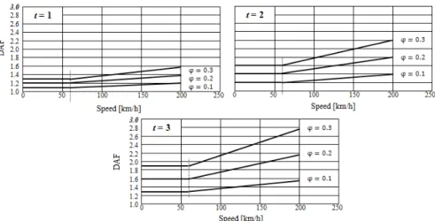
Fig. 2:6 DAF values as a function of the train speed at different track qualities and probabilities ... 33
Fig. 2:7 Testing site and instruments ... 34
Fig. 2:8 Field test to determine the main frequency for rail fastening system ... 35
Fig. 2:9 Quasi-static working curves ... 37
Fig. 2:10 Time-displacement and time-force relationship ... 37
Fig. 2:11 Dynamic testing results ... 38
Fig. 2:12 Measured and simulated time-displacement and time-force curves ... 40
Fig. 2:13 Dynamic amplitude dependent hysteresis loops ... 41
Fig. 2.14 Dynamic amplitude dependent stiffness and damping properties ... 43
Fig. 2:15 Frequency dependent stiffness and damping properties ... 44
Fig. 2:16 Nonlinear displacement-force curve under the influence of preload ... 45
Fig. 2:17 Preload-and-amplitude dependent properties ... 46
CHAPTER 3 Modelling of the rail fastening systems Fig. 3:1 Decomposition diagram of the hysteresis loop of rubber component in rail fastening ... 52
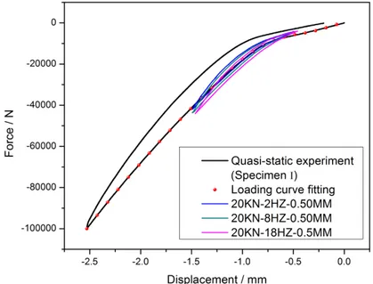
Fig. 3:2 Measured and calculated hysteresis loop of the compressed type fastening system when f=6 Hz and A=0.5mm ... 56
Fig. 3:3 Amplitude and frequency dependent dynamic stiffness ... 57
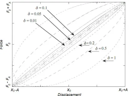
Fig. 3:4 Displacement versus responding force for a linearly viscoelastic rubber material with different damping factors ... 59
Fig. 3:5 Mechanical analogy of the spring-pot combined with an elastic spring ... 61
Fig. 3:6 Quasi-static measured curve superimposed with frequency dependent hysteresis loops of the compressed type fastening system ... 63
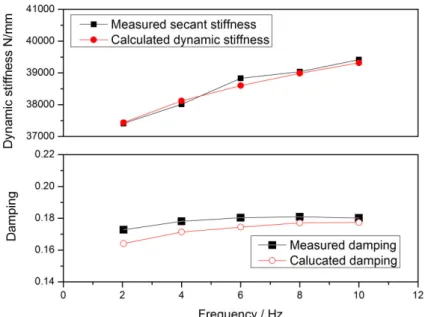
Fig. 3:7 Comparison between the measured and calculated dynamic stiffness and damping for the testing condition of and ... 65
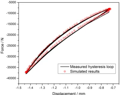
Fig. 3:8 Compared hysteresis loop of measurement and calculation as , and ... 66 Fig. 3.9 Mechanical analogy of stick-slip friction model and the calculated hysteresis loops 68 Fig. 3:10 Mechanical analogy of smooth friction model and the calculated hysteresis loops 69
VII
Fig. 3:11 Mechanical analogy of linear viscous damper and the calculated hysteresis loop .. 71
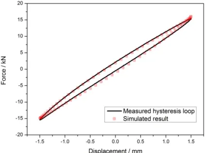
Fig. 3:12 Comparison between measured and simulated hysteresis loop of the working condition A=1.5mm and f=0.5Hz ... 74
Fig. 3:13 Amplitude dependence of the stiffness and damping for the shear type fastening system ... 74
Fig. 3.14 Frequency dependent stiffness and damping of the shear type fastening system ... 75
Fig. 3:15 Compared measured and calculated hysteresis loops by using the integrated model at different working conditions ... 76
CHAPTER 4 Fundamental rubber material tests and simulation Fig. 4:1 Uniaxial tension test ... 81
Fig. 4:2 Equal-biaxial tension test ... 83
Fig. 4:3 Uniaxial compression test ... 83
Fig. 4:4 Planar tension test equals to pure shear test by uniaxial constrained tension ... 84
Fig. 4:5 Planar tension test ... 85
Fig. 4:6 Uniaxial tension test results ... 87
Fig. 4:7 Uniaxial compression test results ... 88
Fig. 4:8 Planar tension test results ... 89
Fig. 4:9 Strain-stress relationships of uniaxial tension test, uniaxial compression test, planar tension test as well as the equal-biaxial tension transformed by using Eq. 4:1 ... 89
Fig. 4:10 Thermo-rheologically simple behaviour of rubber-like materials ... 91
Fig. 4:11 Frequency sweep testing results at different temperature ... 92
Fig. 4:12 Main curve at the referent temperature of ... 93
Fig. 4:13 Relationship between shift factor and the corresponding temperature ... 94
Fig. 4:14 Fitting results of the quasi-static testing data ... 100
Fig. 4:15 The measured strain-stress curves compared with the fitting results by using three selected models ... 101
Fig. 4:16 Simulation procedure and results ... 102
Fig. 4:17 Predicting results influenced by the frictional coefficient ... 103
Fig. 4:18 Compared frequency dependent storage modulus by using Prony series and the measurement ... 105
Fig. 4:19 Rheological representation of Bergstrom-Boyce model ... 106
Fig. 4:20 Simulation results by using Bergstrom-Boyce model in comparison with the virtual measured data ... 107
CHAPTER 5 Finite element modelling and experiment-simulation comparison Fig. 5.1 General view of vertical stiffness measurement ... 109
Fig. 5:2 Different mode of rail nodes participating in deformation ... 110
Fig. 5:3 Testing result of the compressed type fastening system ... 113
Fig. 5:4 Test scheme of the compressed type fastening system ... 113
Fig. 5:5 Test scheme and results of the shear type fastening system ... 114
Fig. 5:6 Assembly modelling of the rail fastening specimens in Abaqus ... 115
Fig. 5:7 Simulation of the compressed type specimen ... 116
Fig. 5:8 Simulation of the nonlinear contact of the shear type specimen ... 117
Fig. 5:9 Rubber components of the fastening specimens ... 118
Fig. 5:10 Comparison of the measured and calculated working curves ... 119
VIII
Fig. 5:12 Detailed prediction of the quasi-static working curve of specimen I after eliminating
the boundary nonlinearity ... 120
Fig. 5:13 Influences of boundary constraint on the shear and compression strain ... 121
Fig. 5:14 Stress distribution for bonded or fractional rubber block during compression ... 122
Fig. 5:15 Secant stiffness influenced by frictional coefficient ... 125
Fig. 5:16 Nonlinear feature of the loading curve influenced by frictional coefficient ... 125
Fig. 5:17 Potential self-contact of the rubber component of the compressed type specimen 125 Fig.5:18 Comparison of the measured and calculated fundamental material experiments by using Van Der Waals models ... 127
Fig. 5:19 Maximum strain at the local part of compressed type specimen ... 128
Fig. 5:20 Maximum strain at the local part of shear type specimen ... 129
Fig. 5.21 Quasi-static displacement-force relationships at different loading rate ... 131
Fig. 5:22 Loading rate dependent secant stiffness and energy dissipation ... 131
Fig. 5:23 Transient stiffness induced nonlinear feature of the compressed type specimen .. 132
Fig. 5:24 Excluding the stress relaxation effect by adding a holding stage of specimen I ... 133
Fig. 5:25 Similar process to exclude the stress relaxation effect performed on specimen II 133 Fig. 5:26 Typical responses of a viscoelastic solid ... 134
Fig. 5:27 Calculated hysteresis loops compared with the measurement ... 135
CHAPTER 6 Parameter sensitivity analysing and structural optimization Fig. 6:1 Geometric parameters of both fastening specimens ... 138
Fig. 6:2 Inclined angle dependent vertical stiffness ... 140
Fig. 6:3 The compared vibration transmissibility between the simulated and the calculated results ... 142
Fig. 6:4 Inclined angle influenced force and displacement response ... 143
Fig. 6:5 Damping ratio dependent resonance response ... 144
Fig. 6:6 The vibration isolation efficiency versus the volume of the rubber component... 145
Fig. 6:7 The maximum local strain under the influence of inclined angle ... 146
Fig. 6:8 The maximum local stress under the influence of inclined angle ... 147
Fig. 6:9 Transverse displacement contour of rubber component in half ... 148
Fig. 6:10 Compared vertical and transverse stiffness ... 148
Fig. 6:11 Force transmissibility obtained by using different damping factor ... 155
Fig. 6:12 Force transmissibility under the influence of damping factor ... 157
Fig. 6:13 Comparison between the original model and that with the modified free surfaces 163 Fig. 6:14 Parameter influenced vertical stiffness of the compressed type fastening system . 164 Fig. 6:15 L2 influenced vertical and lateral stiffness ratio ... 166
Fig. 6:16 Comparison between the original compressed type fastening system and the combined compression-and-shear type model ... 168
Fig. 6:17 Another combined compression-and-shear type model ... 169
IX
LIST OF TABLES
TABLES PAGE CHAPTER 2 Experiment of rail fastening systems
Table. 2:1 Rubber component dimensions of the two specimens ... 29
Table. 2:2 The maximum vertical static force obtained with different rail length ... 32
Table. 2:3 The chosen factor depending on confidence interval and track condition factor .. 32
Table. 2:4 Disturbances of track structure... 35
Table. 2:5 Dynamic experiment conditions ... 36
CHAPTER 3 Modelling of the rail fastening systems Table. 3:1 The evaluated stiffness of each order according to Eq. 3:24 ... 64
Table. 3:2 The evaluated parameters of spring-pot according to Eq. 3:19 ... 64
Table. 3:3 Evaluated parameters with the testing results of A=1.5mm and f=0.5Hz ... 73
CHAPTER 4 Fundamental rubber material tests and simulation Table. 4:1 The RMS values for all the fitted models ... 99
Table. 4:2 Evaluated hyperelastic model parameters ... 100
Table. 4:3 Evaluated Prony series ( ) ... 105
Table. 4:4 Evaluated BB model parameters ... 107
CHAPTER 5 Finite element modelling and experiment-simulation comparison Table. 5:1 Stated stiffness and the corresponding loading intervals ... 111
CHAPTER 6 Parameter sensitivity analysing and structural optimization Table. 6:1 The compared natural frequency from simulation and calculation by using Eq. 6:1 ... 141
1
Chapter 1
Research background
1.1
Track structure
1.1.1 Ballasted track structure
Ballasted track structure which is also called ―classical track‖ or ―conventional track‖ consists basically of a flat framework made up of rails and sleepers supported on ballast [1]. Since the beginning of the railways, principle of the ballasted track structure has not changed substantially. Important developments since II World War includes introduction of continuous welded rail, use of concrete sleepers, heavier rail-profiles, innovative elastic fastenings, mechanization of maintenance, and introduction of advanced measuring equipment and maintenance management systems. As a result, the traditional ballasted track structure still can satisfy the demands in nowadays, as demonstrated by the TGV in France. France is the country mostly admires the ballasted superstructure in the new era of railway system all over the world due to their advanced maintenance instruments. The main advantages of ballasted track are, for examples: proven technology, relatively low construction costs, simple replacement of track components, relatively simple correction of track geometry, i.e. maintenance, small adjustments of track curves possible, good drainage properties, good elasticity and good damping of noise and vibrations. Generally in a ballasted track structure, ballast bed rests on a sub-ballast layer which forms the transition layer to the formation. The rails and sleepers are then connected by fastenings. These components and other structures such as switches and crossings are all considered as part of the track. Since the ballast bed consists of a layer of loose, coarse grained material which, as a result of the internal friction between the grains, can absorb considerable compressive stress, but no tensile stress. The bearing strength of the ballast bed in the vertical direction is considerable, but in the lateral and longitudinal direction it is clearly reduced. In addition, the thickness of the ballast bed should be such that the subgrade is loaded as uniformly as possible. The optimum thickness is usually 25-30 cm measured from the lower side of the sleeper.
2
1.1.1.1 Concrete sleepers
In ballasted track the rails rest on sleepers and together form the built-up portion of the superstructure. Timber and concrete and to a limited extent steel sleepers are used. In general, the general functions and requirements of sleepers are: to provide support and fixing possibilities for the rail foot and fastenings, to sustain rail forces and transfer them uniformly, to preserve track gauge and rail inclination, to provide adequate electrical insulation and to be resistant to mechanical influences and weathering over a long time period, etc.
Due to the scarcity of wood, the introduction of CWR track and the improvements in concrete technology and pre-stressing techniques, concrete sleepers became significantly developed and used in the newly constructed ballasted track structures. Generally speaking, concrete sleepers have such advantages as heavy weight which is useful in connection with stability of CWR track, long service life and can be replaced easily, as well as relatively simple to manufacture. Moreover, climatic influences have little effect on the concrete sleepers which also significantly enhances its service life compared with the timber sleepers.
However, concrete sleepers still have such many drawbacks as being less elastic than wood, susceptible to corrugations and poor quality welds, even risk of damage from impacts. In addition, dynamic loads and ballast stresses could even be as much as 25% higher. At this situation, elastic properties of whole track structure needs to be supplemented by such measures like continuous ballast bed and sleepers and the innovative fastening systems, especially on non-moveable bridges and viaducts. In order to improve the structural behaviour of ballasted track with concrete sleepers, other developments are also discussed in section 1.1.1.2 and 1.1.1.3.
1.1.1.2 Ballast mats and soffit pad
Installing resilient mats between the bottom of the ballast and the subgrade surface (normally tunnel floor and bridge deck) has been employed as an elasticity-improved method for ballasted track. No matter which type of ballast mats such as profiled mats, granular mats and foam mats, the top layer consists of a hard protection layer preventing ballast grans to penetrate into the mat surface. Generally speaking, the mat‘s thickness is approximately 3cm in total. The rubber layer produces damping by changing the motion of the ballast; while it is
3
not as a result of significant energy absorption within the layer itself. In other words, the object of inserting the rubber layer is to introduce resilience and hence generate a mass-spring effect carrying away energy. Brief, the softer the mats are the larger and faster the vibrations are attenuated.
Another way to attenuate track vibrations is to use a sleeper soffit pad which is similar as the ballast mats, while the soffit pads are placed between the sleeper and the ballast. The composite pad comprises 22mm of rubber bonded cork normally, also with a hard facing to prevent damage by ballast particles.
1.1.1.3 Innovative fastening system
The term ―fastening system‖ was considered as an integration including all components together forming the structural connection between rail and sleeps. There are a great variety of fastening systems worldwide and they are introduced in order to keep up with the changes in requirements and options; the choice of fastening also greatly depends on the properties of sleepers. Generally speaking, the rail fastening systems have such functions and requirements as: to ―absorb‖ the rail force elastically and transfer them to the sleeper, to damp vibrations and impacts cause and to provide electrical insulation between the rails and sleepers especially in the case of concrete sleepers. In the long history of ballasted structure with concrete sleepers, a lot of innovative fastening systems have been introduced to meet the new requirement such as anti-vibration requirement on bridge or in tunnels, track geometry accurate keeping for high speed railway and so on. Examples of the first group of innovative fastening systems include those with resilient baseplate and/or resilient rail pad.
Though the rail can be fastened to the sleepers with or without the use of steel baseplates which provides sloping upper surfaces and upright ribs between which the rail can be well locked, the baseplate has the following advantages: vertical load can be distributed over much larger area of the sleeper and this may lengthen the sleeper‘s service life; horizontal load can be absorbed much better due to friction effect and also because it is distributed over all the fastening anchored in the sleeper; baseplates are also excellent for sustaining larger lateral forces if large cant deficiencies are provided; they also have a higher bending stiffness and grooves in the ribs can also provide good fastening locations of the rail;
4
baseplates also gives extra weight to the sleepers, etc. Noteworthy that this kind of rail fastening systems with a resilient pad underlying baseplate (sometimes there are more than one layer of the baseplate and baseplate pad) are not only used in the ballasted track structures but also can be seen in slab track. Similar, the function of rail pads is to transfer the rail load to the sleeper while filtering out the high frequency force components. Modern rail pads vary considerably in material properties (rubber or foam structured) and in appearance such as with grooved surfaces or studded surface. Traditionally, the rail pads are relatively stiff in order to effectively reduce sleeper strains arising from the high frequency wheel-rail load; while softer rail pads are used in a lot of new railway lines with stiffness of about 70-90kN/mm, especially if combined with concrete sleepers.
Given the advantages of resilient baseplate and rail pads, the drawbacks of this type of rail fastening systems on the other hand are relatively high price because a typically classic in-direct fastening system consists of a baseplate fixed to the sleeper using coach screws and clip bolts, rigid sleeper clips, spring washers and nuts to rails. The clip bolt is inserted into the holes in the plate. Besides the expensive cost, the elasticity of the baseplate type rail fastening systems are also not enough, sometimes, to meet the resilience requirements since the fastening derives its vertical elasticity only from the two or more layer of resilient pads in compression.
In a word, with ballasted track vibrations may be reduced by increasing the ballast depth, installing resilient mats between the bottom of the ballast and structure surface, inserting sleeper soffit pads with the pads between sleepers and ballast, or introducing innovative fastening systems with resilient baseplate pad and rail pad and some other highly elastic fastening systems according to special anti-vibration requirements. Studies show that a reduction of 6 dB at frequencies below 10 Hz by increasing the ballast depth from 30 to 75 cm, however this is definitely not an attractive solution because of the costs, the weight and the extra height. This is why the resilient mats, sleeper pads as well as a great varies of innovative fastening systems are more and more dominated in the newly constructed ballasted rail way lines.
5
1.1.2 Slab track
Though most of the current track structures are still of traditional ballasted type, amplifications tend more and more towards non-ballasted track (slab track) whose major advantages are low maintenance, high availability, low structure height and relatively low structure weight. Of the most important, slab track is very competitive from the cost point of view since maintenance for ballasted track structures is much more intensive. According to research literatures, night time possessions often last no longer than 5 hours or even less on European networks, whose intensive traffic becomes more and more difficult to carry out the maintenance and renewal work. In a word, one of the severe problems of ballasted track is the high cycle costing besides investment costs; another prominent problem is the slow deterioration of the ballast material since ballast loose grain wandering and breaking up may cause increasing geometrical unevenness and ballast bed clogging may cause drainage problems. However, slab track can provide much higher lateral and longitudinal stability and deviation of the track is less likely to happen. The condition of the track geometry is therefore good enough and also will improve passenger comfort and decreases considerably the amount of maintenance. Specifically, in comparison to ballasted track structure slab track is to a large extent maintenance free since for which tamping and ballast cleaning as well as track lining is nearly unnecessary (amounting to 20% to 30% of the maintenance costs of ballasted track); as a result, slab track system has nearly the maximum availability and there is hardly any hindrance to residents; service life of the slab track is also largely increased; the excess of superelevation and cant deficiency at special cases, such as the mixed use of freight and passenger trains, does not cause altering of the track position; adjustment up to 26mm in vertical direction and 5mm in horizontal positions are also possible to counteract small deformations. Besides, relatively reduced height and weight, track accessibility to the road vehicles and bicycles, preventing the release of dust from the ballast bed into the environment and so on are all incidental advantages of slab track systems.
Slab track is well acceptable either in high-speed railway lines or metro networks also civil structures like bridges and tunnels currently. There is a large variety of existing superstructure designs of slab track system [2-4] which can be generally derived into three main types except the continuous rail support applied primarily for tramway, sleepers or blocks embedded in concrete or top of asphalt-concrete roadbed, prefabricated concreted slabs,
6
concrete slabs and sleepers with high elastic fastening systems. Brief description of each kind will be discussed in the following sections.
1.1.2.1 Sleepers or blocks embedded in concrete
Concrete sleepers embedded in concrete bed are most commonly used in Germany for newly constructed high speed railway lines, such as the famous Rheda system since 1970 [3-7] and Zublin system since 1974 [3-4,8]. Other examples of concrete sleepers embedded in slab bed are low vibration track (LVT) and the Stedef system [9]. This type of embedded elastic blocks has proved to be one of the perfect solutions for all types of slab track systems, irrespective if that is a high-speed line where accurate track geometry is required, or within the city centre in the metro system where vibration attenuation is of primary importance. It is therefore not surprising that three of the four longest tunnels in the world are included in over 100km of the LVT system installed. The LVT system consists of a concrete block, a resilient pad and a rubber boot surrounded by unreinforced concrete. Except a piece of rail pad nearly no extra demands are required on the rail fixation system.
1.1.2.2 Prefabricated slabs
Prefabricated slabs have already applied in a lot of different places all over the world which considerably contributes to track structure qualities. Moreover, the high level of mechanization, labour-saving construction and a lot of other advantages make it very competitive in slab track structure. The most well-known example of the prefabricated slabs is the one used in Shinkansen-lines of Japan, whose working principle is also used in IPA-system in Italy. The prefabricated slab used firstly on the high speed railway line between Osaka and Okayama on the Sanyo Shinkansen, Japan, consists of a layer of cement asphalt on the structural surface such as a viaduct or other rugged bed, cylindrical stoppers to prevent lateral and longitudinal movement, and a reinforced concrete slab on above the cement mortar layer. In total, one slab weighs about five tons.
Another kind of famous slab track system is referred to as ―floating slab track‖ consisting of a pre-cast reinforced concrete slab on the resilient bearings made of rubber material or steel springs, in order to form a large isolated mass and therefore low natural frequency mass spring system. It thus can provide large reduction of force transmissibility and
7
vibration isolation efficiency for metro systems. Examples include the short pre-cast slab with double sleepers applied in Toronto, the Eisenmann track applied in Munich and Frankfurt as well as New York subway, etc.
1.1.2.3 Elastic fastening systems
There are dramatically lots of elastic rail fastening systems in modern slab track structures after innovative fastening systems with resilient baseplate and rail pad have been introduced to ballasted track. Germany, England, Australia, Japan and China are all highly advanced countries in the fastening systems industry. Generally speaking, fastening systems are designed and selected due to a lot of reasons, for instance the demand of anti-vibration grade, requests for integrity and maintenance, restricts of accessing in the railway line, compatibility with existing lines in a renewed project, terrain limitation, and so on.
Elastic fastening systems contains three different types in general, the unbounded elastomer pad under rail and/or a flat baseplate as discussed in section 1.1.1.3, bounded assembly with flat top and bottom plates as well as other non-baseplate elastic fastening systems. Fig. 1:1 (a) shows a typical unbounded compressed type rail fastening system designed and produced by company Tiflex of UK. It was enlightened by the fastening systems used in ballasted track and was developed initially for the first group of non-ballasted track construction, which took place in Netherlands and Spain. The objective was to provide approaching resilience in non-ballasted track construction as ballasted track structure and to reduce the ground borne vibration with two layers of flat rubber pads, i.e. rail pad and baseplate pad. A great deal of analogical rail fastenings from different countries can be recited, see Fig. 1:1 (b-e). Though introduce different clamping, fixing, insulate components according to different engineering requirements and sometime few more layers of resilient pad are introduced in order to apply more elasticity, they keep the basic resilience principle with vertically deformed elastic rubber pad and as a result they are called compressed-type fastening systems.
Pandrol VANGUARD is neither a bonded nor an unbounded compressive fastening system, but a typical shear type fastening systems which cushions vertical force from passing trains by rubber component in shear deformation mode, see Fig. 2:2. Pandrol VANGUARD,
8
with a nominal static stiffness value as low as 5kN/mm, has a remarkable vibration isolation performance without significant dynamic gauge widening under traffic. The significant reduction of vibration and secondary noise makes it ideal for applications in the most sensitive areas to the environmental concerns. Since been demonstrated to be practical and effective all over the world such as London, South korea, China, Singapore since 2002. Shear type rail fastening systems represented by Pandrol VANGUARD have been recognized as a highly innovative solution for rail fixings particularly in challenging circumstances, achieving significant rail noise suppression, and in the same time, with less construction cost in comparison with in-situ resilient concrete slab and floating slab track systems.
(a) Fastening system with resilient pads from Tiflex of UK (rail pad and baseplate pad)
(b) Vossloh W14 from Germany (c) Pandrol VIPA from UK
(d) Getzner from Australia (e) Tie captive system from Amsted RPS of America Fig. 1:1 Un-bonded compressed type rail fastening systems
9
Fig. 1:2 VANGUARD from Pandrol of UK
The very high elasticity of PANDROL VANGUARD is due mainly to the low shear modulus of rubber material compared of compressive modulus and the dual stiffness capability designed for sake of safety also takes the advantage of compressive property of rubber material. In fact, shear type rail fastening system with high resilience and sometimes with a double stiffness definition can be traced back to early 60th in the 19 century when Cologne Egg was newly designed and manufactured by Clouth Gummiwerke AG company [10]. Cologne Egg is the first fastening system making full use of the advantages of shear elasticity of rubber material. The novel design was rapidly approved to be of excellent quality in high vibration attenuating occasions. In 1983, the Washington Metropolitan Area Transit Authority‘s (WMATA) Metrorail systems had been seeking an alternative of floating slab track structure for mitigating underground noise and vibration and conducted an in-service testing program of Cologne Egg fastening systems [11]. Testing results indicated that with the egg-shaped rail fastener WMATA can not only find an alternative method for mitigating underground vibrations but also save 3.5 million dollars in the new construction by replacing the floating slabs with the egg-shaped fasteners. Subsequently, the fastening system called ATP egg was procured from Advanced Track Products, Inc. (ATP) of Stanton, New Jersey. The shape of ATP egg was portion of the design that was adopted from original Cologne egg. Delokor egg also originates from Cologne egg [12] which is produced by a world leader company (Delokor Rail) dedicating to supplying technical advices and track related products in Australia and overseas of more than 20 years. Delokor egg can also ensure optimum vibration and structure-borne noise reduction in six degrees of movement and achieve a high degree of noise attenuation. An optimized innovation of Delokor egg is that it provides a dual stiffness at the bottom rubber elliptical ring as shown in Fig. 1:3. Specifically, Delokor egg
10
consists of a top plate, a bottom frame plate and a rubber component; all of the three parts are vulcanized directly. From Fig. 1:3 (c), the rubber ring with inclined angle mainly deformed in
(a) Top view (b) Exploded view (c) Side view Fig. 1:3 Delokor egg rail fastening system
shear as loaded vertically. Yet, when vertical displacement is beyond a limit the bottom surface of rubber component reaches the under-surface of iron frame and the overload component begins to deform in compression. This dual stiffness design similar as PANDROL VANGUARD makes use of shear characteristics of rubber material and compressive properties as well.
In addition to the two different kinds of rail fastening systems, i.e. un-bonded compressed and shear type, there is another which is referred to as the bonded compressed type rail fastener. At the early time, bonded compressed type fasteners were designed in order to eliminate the need for steel springs for preventing fatigue failure of anchor bolts. Delkor ALT 1 shown in Fig. 1:4 is a good example of the bounded compressed fastening systems. [13] In fact, it‘s also originated and transformed from the product Alternative 1 designed by company Clouth in the year 1978.
Though being a compressed type of rail fastening system [12], Delokor ALT 1 has generally the same design concept with egg-shape fastener, consisting of a top and a baseplate and a rubber component inside of them. The underside of this rubber component is specially profiled and designed to allow movement of the top plate holding the rail. The outer frame of the ALT 1 is totally encompassed the rubber component and the top plate, making the unit totally fail-safe. This ALT 1 rail fastener also ensures the necessary resilience in all six degrees of movement, subsequently reduces the dynamic stress on the anchoring elements and the base structure. From Fig. 1:4 (c) we can see that, the main body of the rubber component
11
is designed with studded surface and it would help to provide much better compressive elasticity and lower vertical stiffness.
(a) Top view (b) Exploded view (c) Side view Fig. 1:4 Delokor ALT 1 rail fastening system
1.1.2.4 Brief conclusion
Generally speaking, using slab track, i.e. ballastless track, especially in tunnels and bridges in urban railway transit systems, has been finding increasing support mainly due to the much less expensive maintenance cost and more reliable stability. However, certain precautions should be taken such as the superstructure discussed above in the cases traditional ballast bed is substituted by a rigid concrete slab; at the mean while the old fiber sleepers are also taken the place by concrete sleepers. Otherwise, vibration force transmissibility will be increased considerably. Specifically, slab track systems are normally designed to offer equivalent vibration attenuation capability by interposition of resilient layers with the rigid track structures. Either sleepers or blocks embedded in concrete, prefabricated slabs or floating slab track, they are all in fact mass-spring systems.
The concept of inserting a resilient layer is put forward at first for the innovative fastening systems when concrete sleeper was newly introduced into ballasted track structure as discussed in section 1.1.1.1 and 1.1.1.2. However, in comparison, slab track systems, which employs the principle of resiliently mounted blocks and sleepers such as LVT-system, gives much better anti-vibration efficiency by virtue of increased mass. Extending further the principle of increasing the resiliently supported mass, thereby reducing system nature frequency and therefore enhancing vibration isolation effectiveness, slab tracks including a large precast concrete slab such as floating slab track came into wide service all over the world. However, due to the expensive cost of prefabricated slab track, highly elastic rail
12
fastening systems become the alternate at large anti-vibration requirement cases. The highly elastic fastening systems are very competitive compared to other measure due not only to its high anti-vibration effectiveness, but also to the relatively reasonable price and other advantages such as easy replaceability, flexible adjustment, etc.
1.2
Basic concept of vibration isolation
Generally speaking, vibration isolation is concerned with reducing the force magnitude transmitted through a peace of resilient component from the force input terminal to the supporting foundation as shown the single degree system, see Fig.1:5.
Fig. 1:5 Single degree vibration isolation sketch map
As is shown in Fig.1:5, the spring stiffness and the linear damping coefficient represent equivalent parameters of the resilient layer, represents the mass of the component supported above the resilient pad and subjected to input stimulate loadings, is the displacement response of the mounted mass, represents the input cyclic force with the and angle frequency . By the single degree freedom system shown in Fig.1:5, the equation of motion is
, (1:1) where the dot denotes to time derivative. The differential equations of the motion in terms of the damping factor and the un-damped natural frequency of the system are
13
where , is the damping factor of rubber material and √ ⁄ is the undamped natural frequency of the one degree system. The force transfer function of the vibration isolation system is therefore derived as
√ √ , (1:3) where called frequency ratio and √ . The dimensionless
amplitude ratio ⁄ is referred to as force transmissibility and this force transmissibility in Equation 1.3 is normally used to evaluate the vibration isolation efficiency of a rubber elastomer. Fig. 1:6 shows the dependence of the force transmissibility on excitation frequency ratio for various values of the damping factor . It is clearly can be seen from Fig. 1:6 that only if the frequency ratio is greater than √ can transmitted force be smaller than the input force amplitude . For the frequency ratio less than √ , the transmitted force is amplified from . And in the isolation frequency range, the smaller the value of the damping ratio, the smaller the value of force transmissibility and the better the isolation is.
Fig. 1:6 Force transmissibility
Rail fastening systems are typical vibration isolation systems with the rubber component inside which can be described by the elastic and viscous elements; the section of the railway mass is considered as the mounted mass, and the sleeper or concrete slab is
14
supposed to be the boundary. Obviously, lower stiffness of the rail fastening system gives rise to lower nature frequency and smaller force transmissibility. The performance of vibration isolation systems is often evaluated by the transmissibility, which measures the reduction of transmitted force. In order to achieve high isolation efficiency, force transmitted to the foundation needs to be less than the excitation force as much as possible which entails an excitation frequency greater than √ times the natural frequency of the system. As a result, efficient vibration isolation can be obtained from a system with lower natural frequency.
1.3
Research situation of rail fastening systems
1.3.1 Current situation of product development
The introduction of CWR track as well as the use of concrete sleepers and non-ballast track gave rise to the need for fastenings with greater elasticity [1]. As a result, hundreds of elastic rail fastening systems, with their own advantages and drawbacks, were designed and introduced into newly constructed as well as re-constructed railway lines in the world wide. The leading fastening system companies include Vossloh of Germany, Pandrol of UK, Delkor located in Australia, Amsted RPS of USA, and so on. However, though wrong usage of the rail fastening system either for high speed railway or for light ways or others may give rise to expensive consequences and create serious problems such as slowing down or shutting down the production process, excessive and irregular wear of the rail, damage of the mechanical components, damage of the supporting base, shortening the service life of track components, and so on, there is still no yet a general accepted design and selection criterion dedicated to rail fastening systems to the authors‘ knowledge which is similar as the performance evaluation testing standard. Since the dominant design method for rail fastening systems still remains primarily empirical and imitative from developing countries such as China where the railway networks are dramatically constructed, the general and superficial common consensus, such as keeping the track geometry accurate should be the primary position for high speed railway lines while anti-vibration should be the chief task for urban railway lines especially in the sensitive region like schools, libraries, business buildings and closely resident places, is far from enough. Current research aims at enhancing understanding of the mechanical behaviour of fastening systems mainly applied to urban railway networks, concentrates mainly on their resilient property under guidance of basic theories of viscoelastic mechanics,
15
rubber engineering behaviours and vibration isolation mechanism. It‘s believed to be beneficial for cost reduction due to elasticity overdesign and as the theoretical guidance for the performance and service life optimization of two rail fastening systems.
1.3.2 Theoretical study situation
1.3.2.1 Numerical analysis of rubber material and elastomers
The wide use of rubber components (elastomers) in engineering applications should be back to good digest of rubber material properties first. A lot of information of mechanical behaviour of rubber material can be gained from the literature such as [14-23].
The accuracy of a rubber material model, i.e. a viscoelastic model, depends firstly on the ground state elastic strain-stress relations, i.e. hyperelasticity, and then on the evolution constitutive law of the internal variable. [24] Hyperelastic model provides a general capability for modelling rubber-like materials that exhibit highly anisotropic and nonlinear elastic behaviour, which are valid for large elastic strains. For purely elastic finite-strain calculations hyperelastic models are almost the only choice to give realistic predictions of actual material behaviour at large elastic strain (generally larger than 5% in applications). All hyperelastic models are based on the assumption of isotropic behaviour so that strain energy potential can be formulated to define the strain energy stored in the material per unit of reference volume as a function of the strain at that point. There are a great number of strain energy potentials to model approximately incompressible isotropic elastomers. Examples are Mooney Rivlin (first order polynomial model), higher order reduced polynomial model, neo Hookean, Yeoh, Arruda Boyce, Van der Waals, Ogden models, etc. The reduced polynomial and Mooney Rivlin models are viewed as particular cases of the polynomial model; the Yeoh and neo Hookean potentials, in turn, are viewed as special cases of the reduced polynomial model. Therefore, these models are collectively referred to as polynomial models. In general, the strain energy potential forms are written as separable functions of a deviatoric component and a volumetric component, while the deviatoric part of the strain energy function and the volumetric property can also be omitted and assessed by a Poisson‘s ratio.
Since hyperelastic models are based on the definition of strain energy potential, [25] as for an isotropic and incompressible material the function can be expressed either in term of
16
the strain invariants which are functions of the stretch ratios or directly in terms of the stretch ratios themselves. The stretch ratio is defined as the deformed gauge length divided by the initial gauge length by using the nominal engineering strain. Specific hyperelastic models defined by using corresponding strain energy functions will be further discussed in Chapter 4.
Besides hyperelasticity, viscous component of viscoelasticity is also crucial to accurately modelling of rubber materials [26]. In linear viscoelastic theory, it is important to take time as a physical parameter and the detailed comparison between pure elastic solids and viscoelastic solids were presented in [27]. Rubber material shows the phenomena of creep and stress relaxation indicating its dependence on time. Measurements also provide further evidence of this time dependence and also imply a memory effect of rubber material which manifests that stress response at time depends on the preceding strain history or that the strain at time depends on the preceding stress history. As a result, constitutive assumption for the stress at time in terms of the strain history up to time can be denoted by a function which is generally referred to as response function. Similarly, there can also be the dual constitutive assumption for the strain in terms of stress history. In another word, for every statement of stress in terms of strain history, there is a dual statement of strain in terms of history. A central issue in the modelling of viscoelastic material is the determination of the mathematical form of the response function. In the meanwhile, the essence of the linear viscoelasticity consists of two parts: scaling and superposition. In other terms, the assumption of linearity of response states that if a strain history is scaled by a constant , then the corresponding stress is also scaled by and if two strain histories are superposed, the corresponding stresses are also superposed. A very useful corollary of the linearity of viscoelasticity is that there is no interaction between the stress responses to separate strain histories. It however should be noted that this linearity of viscoelasticity on the basis of scaling and superposition does not refer to the shape of any strain-stress curve. It refers to a method of constructing the stress response to a composite strain history by scaling and superposing the stress responses to the component strain histories.
Generally there are two standard approaches that have been used to develop constitutive equations of linear viscoelasticity of rubber materials: mechanical analogy and the Boltzmann superposition principle [28]. By using mechanical analogy, linear viscoelastic behaviour is normally conceived as a linear combination of a spring and a dashpot and
17
correspondingly we can obtain an elastic modulus with units and a viscosity value with units . The mechanical analogues method results in a linear differential equation with constant coefficients relating stress and its rates of different orders. Some of the coefficients are only related to the elastic modulus while some others indicating the viscosity are usually determined from the physical experiments. Three basic models that are typically used to model the linear viscoelasticity of rubber material are the Maxwell model, the Kelvin-Voigt model and the standard linear solid model. However, they only differ from each other in the arrangement of the springs and dashpots. The Maxwell model is represented by a viscous damper connected in series with a purely elastic spring. Since the spring and the dashpot are subjected to the same stress, this model is also known as iso-stress model. Though the Maxwell model can accurately predict the stress decaying exponentially with time, a serious limitation of this model is its inability to correctly represent the creep response of rubber-like material increasing without an up bound. The Kelvin-Voigt model has a Newtonian damper in paralleled with a Hookean elastic spring. Since the two elements are kept in the same strain, this model is also known as iso-strain model. The total stress is derived from the sum of the stress in both of the two branches. Kelvin-Voigt model is extremely accurate in modelling creep in many materials however there is a fatal limitation in its ability to describe the stress relaxation in numerous strained viscoelastic materials. The standard linear solid model which is also referred to as the three-element model is a combination of the Maxwell model and a Hookean spring in parallel. Besides the mechanical analogy measures, a more general approach widely used to model the linear viscoelastic material is the Boltzmann superposition model. The relaxation modulus function of this Boltzmann superposition model consists of an instantaneous relaxation modulus and a gradual relaxation modulus function. It, in fact, can be reduced to the Maxwell mode, if and only if the stress relaxation modulus satisfies specific conditions [29]. Other special cases of Boltzmann model include a generalization of the single spring-dashpot paradigm to one pure elastic spring with multiple spring-dashpot system in parallel which is referred to as generalized Maxwell model or generalized standard linear model or Wiechert model [28-30].
However, linear viscoelastic models are apparently not accurate on every occasion. For example, nonlinear viscoelastic behaviour is often exhibited when the elastomer deformation is large or sometimes the material changes its properties under deformations.
18
Nonlinear viscoelastic theory has been attracting the attention of a large number of researchers over the past century [31-38]. Normally two types of constitutive models can be read from the literatures, one of which is based on the phenomenological mechanical behaviour. In other words, the form of the constitutive model is not based on the explanation of how the properties arise from microscopic structures [32, 39-41]. The other type of nonlinear viscoelastic model entails formulations based on the molecular mechanisms. Doi and Edwads presented a reputation model for concentrated solutions and polymer melts based on an assumption that an entangled polymer molecule, the chain, slides through a ―tube‖. The polymer chain is free to diffuse along the tube axis but cannot move perpendicularly to the tube as other molecules restrict such movement [31]. In [42], the presented Curtiss-Bird model is similar to the Doi-Edwards model but is based on a systematic kinetic development and does not use the phenomenological constraints of a chin in a tube. It was approved that Curtiss-Bird model is more accurate than Doi-Edwards model in predicting the nonlinear behaviour. Furthermore, a thorough review of the molecular types of models, relations between the nonlinear viscoelastic models and molecular structures are given in [43].
Besides the hyperelastic model, linear and nonlinear viscoelastic models, there is also a great deal of research literatures describing the response and developing constitutive models for rubber materials under dynamic loadings. This is due to the significant use of rubber material in engineering practice such as tires, engine mounts, dampen in structures and bridges are all subjected to dynamic load. [21] Industrially-used elastomers make rubber material modelling much more complicated since the filler particles like carbon black change the microstructure of the material in many aspects, some of which are positive such as higher stiffness, damping and crack resistance, better adhesion while others are negative such as the pronounced viscoelastic nonlinearity under cyclic loadings. [44] The most conventional approach in characterizing the dynamic material properties of rubber material is to define the dynamic modulus and damping factor of the rubber in frequency domain in terms of a storage modulus and a loss modulus. Dynamic properties of rubber material differ from the quasi-static properties in terms of a hysteresis loop, the larger stiffness value as well as the frequency and dynamic amplitude dependent dynamic stiffness and damping factor in terms of the varied storage modulus and the loss modulus. This content will be further discussed in Chapter 2.
19
Dynamic material analysis test (DMA) is the most common means to measure the frequency dependent properties of rubber material specimens. [5R] Frequency dependency of rubber material means the changing storage and loss modulus along with stimulating dynamic frequency [45-46]. In an attempt to fit the frequency dependent DMA (dynamic material analysis) result, the generalized Maxwell models or Prony series discussed above were often used [47]. Haupt and Lion [48] presented a model with much fewer material constants in comparison with Prony series of high orders to describe the frequency dependency by DMA test by introducing a fractional derivative calculus to describe frequency dependent relaxation function. There are a great number of other constitutive models addressing the steady-state rate-dependent behaviour of rubber material subjected to cyclic loadings. The advantages of Bergstrom-Boyce model or briefly referred to as BB model [49, 50] compared to the traditional viscoelastic models such as Prony series is its capability of indicating the frequency dependent hysteresis loss. However, it was found that BB model doesn‘t demonstrate the hysteresis property increasing with enlarged strain rate at relatively higher range. A more recent viscoelastic constitutive model by Tomita et al. [51] addresses the dependence of the hysteresis losses on the strain rate during cyclic loading. In contrast to the micro-mechanistic approach, rate-dependent constitutive models have also been derived on the basis of continuum thermodynamics [52-56], by using which the Helmholz free energy is split into equilibrium and non-equilibrium components, which give the equilibrium stress and viscosity-controlled overstress, respectively. It is worthwhile to note that BB model will be further discussed since it is used in the FEA part of current research in Chapter 4-7; this is becasue BB model is embedded in Abaqus and also because the main working frequency range of rail fastening system is relatively low which is within the BB model‘s applicability. The evolution law proposed in BB model is a more general representation of the viscoelastic model of Reese and Govindjee [57]. By ignoring the volumetric viscosity term in the finite viscoelasticity model and extending the materially linear evolution of Reese and Govindjee, BB model was obtained. It was already demonstrated that the algorithmic implementation of the model can be done similarly to the algorithm proposed by Simo and Miehe [58] and by Simo [59]. Integration of the evolution law is carried out by an exponential mapping algorithm [60, 61] and such approach has been used to finite viscoelasticity by Rsses and Govindjee [57].