HAL Id: tel-03156642
https://pastel.archives-ouvertes.fr/tel-03156642
Submitted on 2 Mar 2021HAL is a multi-disciplinary open access archive for the deposit and dissemination of sci-entific research documents, whether they are pub-lished or not. The documents may come from teaching and research institutions in France or abroad, or from public or private research centers.
L’archive ouverte pluridisciplinaire HAL, est destinée au dépôt et à la diffusion de documents scientifiques de niveau recherche, publiés ou non, émanant des établissements d’enseignement et de recherche français ou étrangers, des laboratoires publics ou privés.
Self-meshed autonomous LTE/LTE-A radio access
network for constrained environments
Romain Favraud
To cite this version:
Romain Favraud. Self-meshed autonomous LTE/LTE-A radio access network for constrained envi-ronments. Networking and Internet Architecture [cs.NI]. Télécom ParisTech, 2017. English. �NNT : 2017ENST0058�. �tel-03156642�
2017-ENST-0058
EDITE - ED 130
Doctorat ParisTech
T H È S E
pour obtenir le grade de docteur délivré par
TELECOM ParisTech
Spécialité « Electronique et Communications »
présentée et soutenue publiquement parRomain FAVRAUD
le 22 Novembre 2017Réseau d’accès radio LTE/LTE-A autonome et maillé pour
environnements contraints
Directeur de thèse : Navid NIKAEIN
Jury
M. Christian BONNET,Professeur, Eurecom, France Président
Mme Carla-Fabiana CHIASSERINI,Professeur associé, Politecnico di Torino, Italie Rapporteur M. Riku JÄNTTI,Professeur associé, Aalto University, Finlande Rapporteur M. Tommy SVENSSON,Professeur, Chalmers University of Technology, Suède Examinateur M. Klaus MOESSNER,Professeur, University of Surrey, Royaume-Uni Examinateur
TELECOM ParisTech
A B S T R A C T
Performance of military communication systems is nowadays im-proving slowly compared to commercial systems which puts inter-ests in evolving mature commercial systems for military usage. In parallel,Public Safety (PS)communication systems are changing due to emergence of Long Term Evolution (LTE) as a mature solution to replace the legacy ones while providing new services. However,
LTE is initially designed for commercial cellular network and need to be further evolved to tackle the substantial requirements of pub-lic safety use cases. For instance, opportunistic deployments require modifications to enable the autonomous operation and meshing of moving base stations while satisfying heterogeneous frequency band availability. In this thesis, we develop a complete solution to answer constrained PS and military use cases allowing to wirelessly mesh mobile network nodes and to provide access to standard user equip-ment while only requiring a single radio/LTEband.
Starting from PS and military communication systems landscape and use cases, we present the potential scenarios and derive func-tional requirements for future wireless communication systems to al-low new services and coverage of these use cases. We further un-derline the specific constraints applying to these communication sys-tems due their specific environment of use, especially limited avail-ability of frequency resources. This leads to the selection of LTEas
the Radio Access Technology (RAT)for both backhaul and access of
the wireless system. We then review current LTE state of the art andLTEsystems and compare them against these requirements. Un-derlining the limitations of such systems, we detail the challenges faced by aLTEsolution that would answer these requirements. Then, we present a novel network infrastructure architecture that enables multi-hop LTEmesh networking for nomadic and autonomous base stations via in-band self-backhauling relying on a new base station:
the enhanced evolved Node B (e2NB). We detail the building blocks
of the architecture to answer the multiple challenges. Specifically, we investigate the coordination and orchestration functionality within the proposed architecture and propose a cross layer hierarchical re-source scheduling algorithm in order to efficiently meet Quality of
Service (QoS)requirements for real-time traffic while maximizing the
throughput for elastic flows. To demonstrate the feasibility and relia-bility of our proposed architecture, we implement the corresponding self-backhauling air interface based onOpen Air Interface (OAI) plat-form and compare with the legacyLTEair-interface. We then evaluate the efficiency and adaptability of our proposed resource scheduling
iv
algorithm in various network topologies and heterogeneous traffic flows with QoS requirements. Finally, we summarize the remaining uncertainties concerning real-field deployments and we conclude this study.
R É S U M É
Comparées à celles de systèmes de communications civils, les per-formances des systèmes de communication militaires s’améliorent lentement aujourd’hui. Cela rend intéressant l’évolution de systèmes de communication civils matures pour un usage militaire. En paral-lèle, les systèmes de communications pour les réseaux de sécurité publique sont en train d’évoluer suite à l’émergence de la techno-logie Long Term Evolution (LTE) comme une solution fiable et ma-ture pour remplacer les systèmes précédents. Cependant, le LTE a initialement été conçu pour les réseaux cellulaires commerciaux et nécessite des adaptations pour répondre aux exigences des réseaux de sécurité publique. Par exemple, la réalisation de déploiements op-portunistes nécessite des modifications afin de permettre le fonction-nement autonome et maillé de stations de base mobile qui tiennent compte et s’adaptent aux bandes de fréquences disponibles. Dans cette thèse, nous développons une solution complète permettant de répondre aux cas d’utilisation contraints auxquels font face les organi-sations de sécurité publique et militaires. Cette solution permet, sur une seule bande de fréquence LTE, le maillage sans fil de stations de base mobiles tout en maintenant l’accès au réseau de terminaux mobiles standards.
Nous commençons par présenter les cas d’utilisation et les sys-tèmes de communications utilisés par les autorités militaires et de sécurité publique. Nous présentons alors les scénarios associés et en dérivons des exigences fonctionnelles afin de concevoir un nouveau système de communication couvrant ces cas d’utilisations et appor-tant de nouveaux services. Nous soulignons ensuite les contraintes spécifiques qui s’appliquent à ces systèmes de communication dues aux environnements spécifiques dans lesquels ils sont utilisés, en par-ticulier les contraintes limitant l’accès aux ressources spectrales. Ces contraintes influencent la conception du système et mènent au choix duLTEpour réaliser à la fois le réseau d’accès sans fil pour terminaux mobiles et les interconnexions entre les stations de base du système. Nous présentons alors un état de l’art rapide du LTE et comparons les fonctionnalités actuellement disponibles avec les exigences précé-demment définies. Soulignant les limitations des systèmes standards, nous détaillons les défis auxquels doit faire face une solution basée sur le LTE pour répondre aux dites exigences. Ensuite, nous présen-tons une nouvelle architecture d’infrastructure réseau qui permet la création de réseaux maillés LTE multi-bonds. Celle-ci s’appuie sur une nouvelle station de base autonome et mobile qui dispose d’une fonctionnalité de maillage intra-bande : l’enhanced evolved Node B
vi
(e2NB). Nous détaillons ensuite les composants de cette architecture
et de cette station de base pour répondre aux multiples défis identi-fiés. Plus particulièrement, nous évaluons le besoin de coordination entre stations de base et nous proposons un algorithme d’ordonnance-ment de ressources radio inter-couches afin de satisfaire les exigences de qualité de service des flux temps réel tout en maximisant le débit des flux élastiques. Pour démontrer la faisabilité de l’architecture pro-posée, nous implémentons l’interface sans fil inter stations de base sur la plateforme de radio logicielle OpenAirInterface et la compa-rons avec l’interfaceLTEclassique. Ensuite, nous évaluons l’efficacité et l’adaptabilité de l’algorithme d’ordonnancement proposé sur diffé-rentes topologies auxquelles nous appliquons des flux hétérogènes en termes d’exigences de qualité de service. Finalement, nous résumons les incertitudes restantes concernant les déploiements sur le terrain et nous concluons cette étude.
A C K N O W L E D G M E N T S
This has not been an always easy journey. "Learn the hard way!" they said. I guess I somehow did, and I am quite happy that this journey was successful and is finally, as I am writing, coming to an end. But even though pursuing a PhD degree may look like a long and solitary walk, it cannot be started and surely not finished alone.
That is why I would like to take these few lines to thank all the people that made this possible.
First, I would like to thank Franck Andreani and Cyril Gazzano from Naval Group who offered me this opportunity, as well as Joël Caravetta, Jean-Hugues Chauvot, Patrick Saretti and all the other peo-ple in Naval Group I had the chance to work with.
I, of course, thank my PhD advisor, Navid Nikaein, first for accept-ing to supervise this thesis, and mostly, for havaccept-ing been able to guide me successfully through it.
I would like to thank all members of the thesis committee for tak-ing the time to read this thesis and providtak-ing their constructive and helpful feedback.
I would like to thank my colleagues and friends from Eurecom, who greatly helped me getting over the difficulties and provided a lot of interesting discussions and ideas, as well as many laughs: Lau-rent Gallo, Konstantinos Alexandris, Jingjing Zhang, Chia-Yu Chang, Irfan Khan, Paolo Viotti, Pierre-Antoine Vervier, Xiwen Jiang, Qian-rui Li, Yongchao Tian, Shengyun Liu, Haifan Yin, Ruggero Schiavi, Anta Huang, Francesco Pace, Daniele Venzano, Kurt Cutajar, Elena Lukashova and many others that made that journey enjoyable!
I sincerely thank my friends Colin, Jawad, Sammy and Lucas, who were far away but more than supportive and helpful all along, as well as Agnès for providing me the necessary joy over the final steps.
Finally, I thank my parents and my sister for continuously support-ing me in my life, and in that maybe not so crazy idea this was!
C O N T E N T S
Abstract iii
Résumé v
Acknowledgments vii
Contents viii
List of Figures xiii
List of Tables xv
1 i n t r o d u c t i o n 1
1.1 Motivations . . . 1
1.2 Contributions . . . 2
2 s tat e o f t h e a r t a n d p r o b l e m s tat e m e n t 5 2.1 Uses cases and current solutions . . . 5
2.1.1 Military and Naval uses cases . . . 5
2.1.2 Public Safety uses cases . . . 8
2.2 Network topologies . . . 9
2.2.1 Scenarios . . . 9
2.2.2 Scenarios of reference . . . 12
2.3 Problem Statement . . . 13
2.3.1 High level requirements . . . 14
3 d e s i g n c o n s t r a i n t s a n d r at c h o i c e 17 3.1 External constraints . . . 17
3.2 RAT of autonomous network . . . 18
3.2.1 LTE state of the art . . . 19
3.2.2 Backhaul link consideration . . . 24
4 a r c h i t e c t u r e o f t h e au t o n o m o u s b t s 27 4.1 Challenges . . . 27
4.1.1 Support of Legacy UEs . . . 27
4.1.2 Autonomous operation . . . 27
4.2 Architecture . . . 29
4.3 e2NB states . . . 32
4.4 e2NB network topologies . . . 33
5 d e s i g n e l e m e n t s a n d p r o c e d u r e s o f e 2 n b 35 5.1 Physical layer interfaces . . . 35
5.1.1 Background LTE information . . . 35
5.1.2 Uu interface . . . 36
5.1.3 Un relay interface . . . 38
5.2 Physical layer design issues . . . 43
5.2.1 Synchronization . . . 43
5.2.2 Range limitation . . . 45
5.2.3 HARQ modifications for Un interface . . . 46
5.3 e2NB procedures and parameters configuration . . . . 47
5.3.1 eNB parameters . . . 48
x Contents
5.3.2 vUE attach procedure . . . 48
5.3.3 e2NB operation flow . . . 51
5.4 Core Network logical connectivity . . . 55
5.4.1 MME . . . 55
5.4.2 HSS provisioning and cooperation . . . 56
5.4.3 S/P-GW . . . 56
5.4.4 Routing . . . 56
5.4.5 Application and services . . . 57
6 c o e a l g o r i t h m s 59 6.1 Problem overview . . . 59
6.2 COE role and proposed hierarchical approach . . . 60
6.3 COE Controller Scheduling Algorithm . . . 62
6.3.1 Superframe duration computation (LSuF) . . . . 64
6.3.2 SF allocation for inter-e2NB self-backhauling . . 64
6.3.3 Distributed link scheduling . . . 68
6.4 Relaying direction selection . . . 69
6.5 Extensions to TDD system . . . 70
6.6 Extensions to multi-antenna and multi-sector BTS . . . 71
6.6.1 Analysis of the approach complexity . . . 72
6.7 Interference management . . . 73
6.8 Discussion on security issues . . . 74
7 e x p e r i m e n tat i o n s 75 7.1 Physical channel performance evaluation . . . 75
7.1.1 Computation time . . . 76
7.1.2 Link-level performance . . . 78
7.2 Evaluation of the proposed approach . . . 80
7.2.1 Simulation environment . . . 81
7.2.2 Considered Algorithms . . . 83
7.2.3 Simulation Results . . . 84
7.2.4 Summary . . . 97
7.3 Performance comparison of in-band and out-band de-ployment . . . 99
7.4 Summary . . . 102
7.4.1 Limitations of the experiments . . . 102
7.4.2 Potential improvements of the proposed approach103 8 c o n c l u s i o n 105 8.1 Perspectives and future work . . . 106
9 b i b l i o g r a p h y 109 Appendices 117 a a d d i t i o na l f i g u r e s 119 b r é s u m é e n f r a n ç a i s 123 b.1 Introduction . . . 123 b.1.1 Motivation . . . 123 b.1.2 Contributions . . . 124
b.2 État de l’art et définition de la problématique . . . 126
Contents xi
b.2.2 Communications pour la sécurité publique . . . 128
b.2.3 Topologies réseaux associées . . . 128
b.2.4 Énoncé du problème . . . 128
b.3 Contraintes de conception et choix de la technologie d’accès radio . . . 130
b.3.1 Contraintes externes . . . 130
b.3.2 Choix de la technologie d’accès radio . . . 130
b.4 Architecture de station de base autonome . . . 134
b.4.1 États de l’e2NB . . . 136
b.4.2 Topologies réseaux possibles . . . 136
b.5 Conception détaillée et procédures de l’e2NB . . . 137
b.6 Algorithmes d’ordonnancement . . . 138
b.6.1 Rôle du COE et approche hiérarchique proposée 139 b.7 Expérimentations . . . 140
b.8 Conclusion . . . 141
b.8.1 Perspectives et travaux futurs . . . 142
L I S T O F F I G U R E S
Figure 1 Overview of military and naval communications 6
Figure 2 Network topologies - scenarios 1, 2 and 3. . . . 11
Figure 3 Network topologies - scenarios 4, 5 and 6. . . . 11
Figure 4 Network topologies - scenarios 7 and 8. . . 11
Figure 5 Network topologies - scenarios 9, 10, 11 and 12. 11 Figure 6 Evolution of cellular system standards. . . 19
Figure 7 LTE nominal architecture (Release 8). . . 20
Figure 8 3GPP PS oriented work items. . . 21
Figure 9 Topologies based on standard LTE BTS (1,2,3) and the envisioned LTE network (4). . . 23
Figure 10 e2NB stack. . . 30
Figure 11 Main e2NB states. . . 32
Figure 12 Example of different network topologies based on e2NBs. . . 33
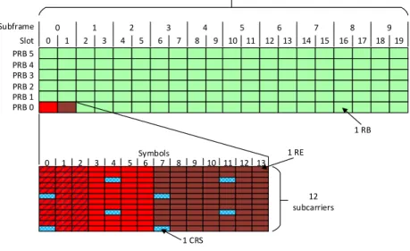
Figure 13 LTE resource grid for a 1.4MHz (6 PRBs) chan-nel width. . . 36
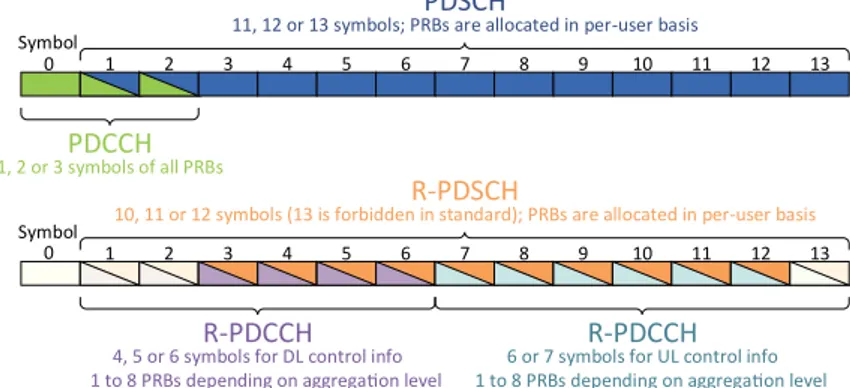
Figure 14 Symbol allocation in a SF for Uu and Un inter-faces. . . 39
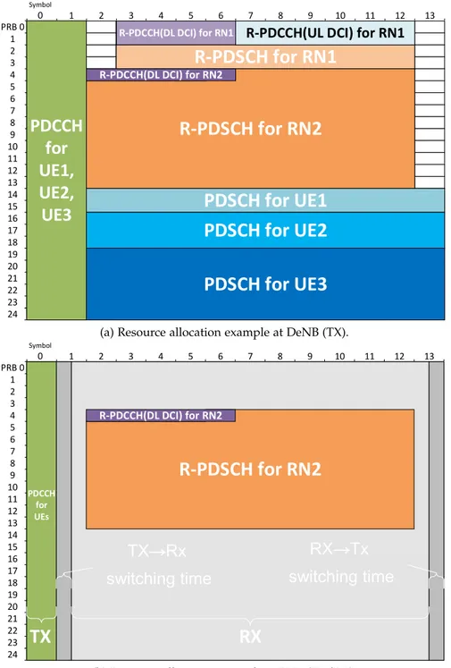
Figure 15 Resource allocation example of DL at DeNB/RN. 41 Figure 16 Non-synchronized e2NB transportation. . . 44
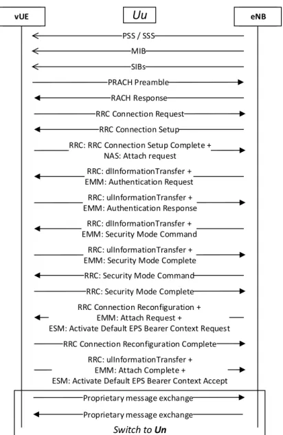
Figure 17 Connection procedure. . . 49
Figure 18 Startup phase operation flow. . . 52
Figure 19 Isolated state operation flow. . . 53
Figure 20 Meshed state operation flow. . . 54
Figure 21 vUE relay state operation flow. . . 55
Figure 22 Coordination and Orchestration Entity archi-tecture. . . 60
Figure 23 R-PDCCH and PDCCH computational time. . 77
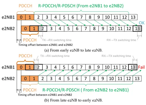
Figure 24 TX/RX time for PDCCH/PDSCH and R-PDCCH/R-PDSCH. . . 77
Figure 25 Minimum SNR level to decode 75% of the TBs. 78 Figure 26 Minimum SNR level for several aggregation levels. . . 80
Figure 27 Considered network topologies. . . 82
Figure 28 Hexagonal topology with 7 e2NBs and 70 UEs using 10MHz in FDD mode. . . 85
Figure 29 Hexagonal topology with 7 e2NBs and 70 UEs using 10MHz in TDD mode. . . 87
Figure 30 Hexagonal topology with 7 e2NBs and 70 UEs using 10MHz in TDD mode or 5MHz in FDD mode. . . 88
xiv List of Figures
Figure 31 Line topology with 7 e2NBs and 70 UEs using 5MHz in FDD mode. . . 89
Figure 32 Line topology with 7 e2NBs and 70 UEs using 10MHz in TDD mode. . . 91
Figure 33 Line topology with 7 e2NBs and 70 UEs using 10MHz in TDD mode or 5MHz in FDD mode. 92
Figure 34 Hexagonal topology with 19 e2NBs and 190 UEs using 5MHz in FDD mode. . . 94
Figure 35 vUE UL transmission successful rate of hexag-onal topology with 19 e2NBs and 190 UEs us-ing 5MHz radio bandwidth of FDD mode un-der UL. 2V. . . . 95
Figure 36 Hexagonal topology with 19 e2NBs and 190 UEs using 10MHz in FDD mode. . . 96
Figure 37 Hexagonal topology with 19 e2NBs and 190 UEs using 10MHz in TDD mode. . . 97
Figure 38 Network topology for in/out-band comparison. 100
Figure 39 Data rate of traffic flow of in/out-band deploy-ments. . . 100
Figure 40 Cumulated data rate of two traffic flows. . . . 101
Figure 41 Hexagonal topology with 7 e2NBs and 70 UEs using a 10MHz FDD configuration. . . 119
Figure 42 Hexagonal topology with 7 e2NBs and 70 UEs using a 10MHz TDD configuration. . . 119
Figure 43 Hexagonal topology with 7 e2NBs and 70 UEs using a 10MHz TDD and a 5MHz FDD config-uration. . . 120
Figure 44 Line topology with 7 e2NBs and 70 UEs using a 5MHz FDD configuration. . . 120
Figure 45 Line topology with 7 e2NBs and 70 UEs using a 10MHz TDD configuration. . . 121
Figure 46 Line topology with 7 e2NBs and 70 UEs using a 10MHz TDD or a 5MHz FDD configuration. 122
Figure 47 Aperçu des communications sans fil militaires et navales . . . 127
Figure 48 Architecture nominale du LTE (Release 8). . . 132
Figure 49 Travaux du 3GPP orientés sécurité publique. . 132
Figure 50 Topologies réseaux réalisables à parti des spé-cifications LTE (1,2,3) et réseau LTE visé (4). . . 133
Figure 51 Architecture de l’e2NB. . . 134
Figure 52 États principaux de l’e2NB. . . 136
Figure 53 Exemples de topologies réseaux obtenues grâce aux e2NBs. . . 137
Figure 54 Architecture du COE (Coordination and Or-chestration Entity). . . 139
L I S T O F TA B L E S
Table 1 Medium range ship-to-ship communication sys-tems vs military satellite . . . 7
Table 2 Possible network scenarios . . . 10
Table 3 Considered scenarios . . . 13
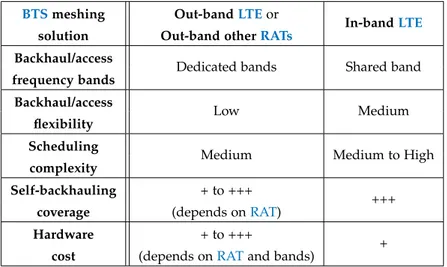
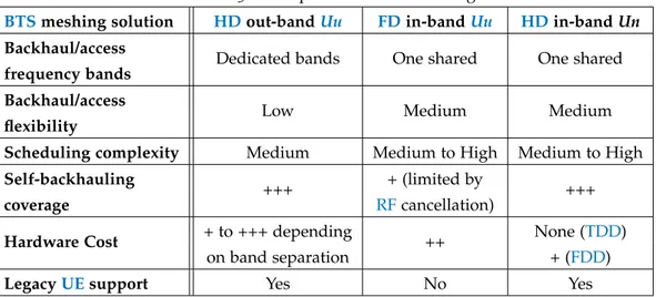
Table 4 Comparison of different LTE meshing solutions 25
Table 5 Comparison of LTE meshing solutions . . . 42
Table 6 Comparison of centralized and distributed sched-ulers . . . 62
Table 7 Compared algorithms with corresponding no-tations . . . 84
Table 8 Summary of the evaluation results . . . 98
Table 9 Systèmes de communication navals à moyenne portée et système de communication par satellite127
1
I N T R O D U C T I O NWireless communications have never been so widely used by hu-mans. While the frequency spectrum is limited, new technologies enabling faster or more energy efficient wireless communications are emerging every year, pushing forwards the possibilities and the ex-pectations of end users.
In such a crowded landscape, Long Term Evolution (LTE) is be-coming the technology reference for 4G cellular networks, as it is increasingly adopted by all major operators all over the world. Cur-rently, LTEis rising to the challenge of addressing several issues (e.g. cellular networks’ capacity crunch, ultra-high bandwidth, ultra-low latency, massive numbers of connections, super-fast mobility, diverse-spectrum access) that speed up the pace towards 5G. Moving cells have been envisioned to expand the coverage and provide higher data-rates at low cost thus enabling several new use cases in
Intel-ligent Transportation System (ITS), Unmanned Aerial Vehicle (UAV)
and drones communications, etc. Moreover, LTEis expected to be an important part of the 5G solution for future networks and also play an essential role in advancingPublic Safety (PS)communications.
1.1 m o t i vat i o n s
In theUnited States of America (USA),LTEhas been chosen up as the next appropriate communication technology to support PS com-munications and it is likely to be the same in Europe. Moreover, several vendors (e.g. Ericsson, Nokia, Huawei, Cisco) are now start-ing to propose LTE-based PS solutions and some of them have been put to real field experimentation.
While existing PS solutions (e.g. Project 25 (P25) and Terrestrial
Trunked Radio (TETRA)) are mature and provide reliable
mission-critical voice communications, their designs cannot meet the new re-quirements and the shift to higher bandwidth applications. In addi-tion,LTEsystem is a commercial cellular network and was not suited in the initial 3rd Generation Partnership Project (3GPP) releases to
supportPSservices and the corresponding requirements like reliabil-ity, confidentialreliabil-ity, securreliabil-ity, group and Device-to-Device (D2D) com-munications. Therefore, the raising question is whether LTEsuffices to be an appropriate solution for PS networks. To address those is-sues,3GPPhas started to define the new scenarios thatLTEwill have
to face and it has released several studies on proximity-based services
(Proximity Services (ProSe)), group and D2D communications,
2 i n t r o d u c t i o n
sion Critical Push-To-Talk (MCPTT), and Isolated Evolved Universal
Terrestrial Radio Access Network (E-UTRAN). These studies define
the requirements regarding User Equipments and evolved Node Bs
(eNBs)to provide PS services depending on theE-UTRAN
availabil-ity and architecture. Particularly, the studies on isolated E-UTRAN
target use cases when one or several eNBs have limited or no access to the Core Network (CN) (Evolved Packet Core (EPC) in LTE) due to a potential disaster, or when there is need to rapidly deploy and use aLTEnetwork outside of the range of the existing infrastructure. In these situations, the isolated E-UTRAN must maintain relevant services accessible for the PS UEs despite the lack of full EPC con-nectivity (e.g. local routing and frequency resource management). However, 3GPP studies do not define how such isolated eNBs of a
single set should communicate together, and leave that to the use of other technologies and vendor specific solutions.
On another hand, military communication systems have for long been the driver of new advancements in the wired and wireless com-munication landscape. However, this has changed. Indeed, the dig-ital revolution has been relying on communication systems and has greatly increase the involvement of private companies to provide reli-able and high performance communication systems. Nowadays, most innovations are coming from these companies targeting a massive consumer market. Moreover, if the military budgets are not getting shrinked, the missions ensured by military authorities are becoming larger at iso-budget. This fact leads military entities to rely more and more onCommercial Off-The-Shelf (COTS)equipment, even for com-munication systems. Thus, simmering interest has arisen around the use ofLTEto provide high data rate and flexible communications for military operations on land or at sea. However, these specific use cases requires support of network topologies and constraints that are absent in the commercial market.
1.2 c o n t r i b u t i o n s
To the best of our knowledge, there have not been extensive re-search and contributions to extend theLTEconnectivity to more than two wireless hops from a base station that has access to theCN with-out making use of with-out-band radios. However, as we will detail in this work, this is of interest for several use cases that have strict require-ments on frequency resources or hardware availability such asPSand military communications. In this thesis, we study how to evolve the
LTE communication systems to enable new use cases in constrained environments relying on autonomous moving cells.
In the first chapter, we introduce the use cases that we are target-ing in our study by reviewtarget-ing the operational situations encountered by military, navy and PS entities. We show the limitations of their
1.2 contributions 3
current wireless communication systems. Then, we present the net-work topologies common toPS, military and other entities that arise in their respective use cases. In light of the previously mentioned lim-itations, we formulate the main problem that this study is targeting to solve: how to enable high data rate autonomous wireless networks based on moving cells able to serve mobile users in constrained envi-ronments. We conclude this first chapter by drawing the functional requirements of a potential solution based on this target. Three con-tributions have enlighten these problems:
— R. Favraud and N. Nikaein, "Wireless mesh backhauling for LTE/LTE-A networks," MILCOM 2015 - 2015 IEEE Military Com-munications Conference, Tampa, FL, 2015, pp. 695-700.
— R. Favraud, A. Apostolaras, N. Nikaein and T. Korakis, "Toward moving public safety networks," in IEEE Communications Mag-azine, vol. 54, no. 3, pp. 14-20, March 2016.
— R. Favraud, A. Apostolaras, N. Nikaein and T. Korakis, "Pub-lic safety networks: Enabling mobility for critical communica-tions," in Wireless Public Safety Networks 2 : A systemic ap-proach, Wiley-ISTE, 2016.
In the second chapter, we start from these requirements that we extend with the external constraints applying to communication sys-tems for PS and military use, such as limitations in available fre-quency resources. We then select LTE as the Radio Access
Technol-ogy (RAT) to be used to provide wireless access to mobile users as
it is the currentRAT of choice for futurePScommunication systems. Thus, we review the current LTE state of the art and we discuss on the selection of the RAT to realize the wireless backhaul to be used by a potential solution. While meshing the Base Transceiver Station
(BTS)using a dedicated RAT seems the easiest, LTE for both access
and backhaul arise as the solution for the most constrained use cases. This has been discussed in the following contribution:
— R. Favraud and N. Nikaein, "Analysis of LTE Relay Interface for Self-Backhauling in LTE Mesh Networks," 2017 IEEE 86th Vehic-ular Technology Conference (VTC-Fall), Toronto, ON, Canada, 2017.
UsingLTEfor both access and backhaul is challenging. In the third chapter, we detail the challenges faced by a LTEsolution that would answer both the functional requirements defined in the first chapter and the external constraints underlined in the second chapter. Then, we present a novel network infrastructure architecture that enables multi-hop LTEmesh networking for nomadic and autonomous base stations via in-band self-backhauling relying on a new BTS: the
en-hanced evolved Node B (e2NB). We present thee2NBbuilding blocks,
such as theeNBandCNcomponents as well as the newly defined
4 i n t r o d u c t i o n
e2NBinternal states that allow the dynamic meshing of theBTSand finish this chapter with examples of resulting network topologies.
Then, we detail on the specific e2NB design elements and proce-dures in the fourth chapter. Especially, we explore the choice of the physical layer interfaces by first underlining the limitations of the legacy User to UTRAN (Uu) interface before analytically comparing
Half Duplex (HD)andFull Duplex (FD)approaches justifying the use
of theLTErelay (Un) interface. We then present the main features and procedures of thee2NBto enable the discovery and initial connection of the BTSs. We then present in details thee2NBoperation flow and states allowing for node discovery and network split-and-merge be-fore discussing on the specific CN features that are required. This operation flows and states have been first presented in the following contribution:
— R. Favraud, C. Y. Chang and N. Nikaein, "Autonomous Self-Backhauled LTE Mesh Network With QoS Guarantee," in IEEE Access, vol. 6, pp. 4083-4117, 2018.
In the fifth chapter, we investigate the coordination and orchestra-tion funcorchestra-tionality within the proposed architecture. As we are tar-geting an applicable solution with constrained resources suitable for
both Frequency Division Duplexing (FDD) and Time Division
Du-plexing (TDD) operation, we propose a cross layer hierarchical
re-source scheduling algorithm in order to efficiently meet Quality of
Service (QoS)requirements for real-time traffic while maximizing the
throughput for elastic flows. This problem is tackled in two contribu-tions:
— R. Favraud, N. Nikaein and C. Y. Chang, "QoS Guarantee in Self-Backhauled LTE Mesh Networks," GLOBECOM 2017 - 2017 IEEE Global Communications Conference, Singapore, 2017. — R. Favraud, C. Y. Chang and N. Nikaein, "Self-backhauled
au-tonomous LTE mesh networks," 2017 IEEE 13th International Conference on Wireless and Mobile Computing, Networking and Communications (WiMob), Rome, 2017.
Finally, in the sixth chapter, we aim to demonstrate the feasibility and reliability of our proposed architecture, We first implement the corresponding self-backhauling air interface (Un interface) on Open
Air Interface (OAI) platform and compare with the legacy LTE
air-interface on both computing requirements and spectral efficiency. We then evaluate the efficiency and adaptability of our proposed hierar-chical resource scheduling algorithm in various network topologies and heterogeneous traffic flows with QoS requirements to show its adaptability and limitations in bothFDDandTDDconfigurations.
In the conclusion, we summarize the remaining uncertainties con-cerning real-field deployments and we conclude this study drawing the required steps to push the proposed solution forward to a func-tional Radio Frequency (RF)wireless communication system.
2
S TAT E O F T H E A R T A N D P R O B L E M S TAT E M E N TIn this chapter, we introduce the specific use cases that we are tar-geting in our study. We first briefly review the operational situations encountered by military and navy entities and give a brief overview of medium range naval communication systems. Then, we reviewPS
use cases and requirements as well as currentPScommunication sys-tems. We present the common network topologies that can arise for both military and PS communication systems depending on the op-erational situation. Then, summarizing the discovered shortcomings, we formulate the main goal of this study. Finally, we define the high level requirements for a communication system to answer the consid-ered use cases and we review the associated external constraints.
2.1 u s e s c a s e s a n d c u r r e n t s o l u t i o n s
In this section, we briefly review the operational situations that can be encountered by both PS and military organizations and present the associated communication systems and shortcomings.
2.1.1 Military and Naval uses cases
Military authorities are in charge of a very broad range of missions that require use of all possible communication media. Indeed, Mili-tary authorities rely on Command, Control, Communications,
Com-puters, and Intelligence (C4I) to effectively address their missions.
Communications for the military forces are very strategic for control-ling and information sharing in real time among different forces to enable fast reaction to an event, as General Dempsey explains: “In-formation systems and networks provide the means to send, receive, share, and utilize information. The synthesis of advanced communications system capabilities and sound doctrine leads to information superiority, which is essential to success in all military operations” [1].
In most environments, deployed military forces have to rely heavily on wireless communications to answer their communication needs as there is either no fixed infrastructure available (i.e hostile territory) or their mobile behavior prevents them to use any.
For instance, navies are operating at sea, from the sea side to high sea where there is no available infrastructure. Nevertheless, fleet ma-rine forces have to communicate to several entities that can be close or very far away: civil surface ships; military surface ships and sub-marines; airplanes; UAVs and Unmanned Surface Vehicles (USVs);
6 s tat e o f t h e a r t a n d p r o b l e m s tat e m e n t
operational centers at land, etc. Figure 1 provides an overview of
some communication needs of military and Naval Forces.
Legend Satellite Sea Land Air Sea Land UAV Ship Speed boat
Ship Ship Ship
Submarine Aircraft carrier Aircraft Aircraft Head Quarters Ship USV Tank Helicopter Troops HF/VHF/UHF SHF/EHF VLF
Figure 1 – Overview of military and naval communications
To this end, several communication systems are embedded in navy surface ships, leveraging the whole radio spectrum from Very Low
Frequency (VLF)toExtremely High Frequency (EHF)to provide
com-munications from close to far entities. However, communication sys-tems for military and navies are not evolving as fast as civilian com-munication systems while new use cases requiring better performance are emerging.
Current naval medium range communication systems
Particularly, systems for medium range communications from ship to ship, from ship to shore or from ship to drones in optical visi-bility are currently not able to meet the increasing needs of navies regarding data-rate and latency. Indeed, currently deployed commu-nication systems for medium range commucommu-nications rely on Ultra
High Frequency (UHF)radios using dedicated protocols with limited
bandwidth. For instance, for ship-to-ship data communications, the French Navy uses a proprietary UHF RAT deployed in the Réseau
Intranet des Forces Aéro-Navales 2 (RIFAN 2) communication
sys-tem [2] whileNorth Atlantic Treaty Organization (NATO)navies can
cooperate using theUHF SubNetwork Relay (SNR)system [3].
Perfor-mance of these two systems are similar and are compared in Table1
to the French military satellite communication system that provides a global coverage and can also be used to transfer data from one ship to another.
These communication systems are keys for successful operations in Naval Forces (group of 3 to 10 navy ships) where many information can be shared between ships. Their automatic setup and easy main-tenance is highly appreciated by the sailors. However, there is a need
2.1 uses cases and current solutions 7
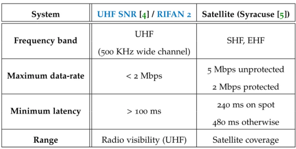
Table 1 – Medium range ship-to-ship communication systems vs military satellite
System UHF SNR[4] /RIFAN 2 Satellite (Syracuse [5])
Frequency band UHF SHF, EHF
(500 KHz wide channel)
Maximum data-rate < 2 Mbps 5Mbps unprotected
2Mbps protected
Minimum latency > 100 ms
240ms on spot 480ms otherwise
Range Radio visibility (UHF) Satellite coverage
for more bandwidth, lower latency and more flexibility to improve the situation awareness, to decrease the operating response time to events and to meet new use cases such as video streaming and high volume data transfers between ships.
While satellite communications can be leveraged for latency flexi-ble data transfers, military satellites are shared among all forces and temporary use of commercial services is expensive.
Moreover, there are also needs for middle range high bandwidth data links for mobile entities (e.g. UAVs,USVs, commandos on board of inflatable boats, etc.) hosted by ships or going around the navy fleet. Nowadays, there is no common solution that answers these var-ious needs: dedicated radios with limited interoperability are often used and WiFi is being experimented for opportunistic links [6].
Last but not least, there is currently no wireless high data rate com-munication system available when sailing close to shore or in port while fast access to land hosted services could be leveraged by the sailors in these situations.
To summarize, a list of requirements for a new wireless medium range naval communication system leveraging the aforementioned problems can be drawn:
— Wireless communications between several ships, between ship and mobiles entities (drones, sailors, etc.), between ship and shore
— Tens of kilometers of range (UHFradio visibility) — High maximum data rates (> 1Mbps)
— Low latency (< 100ms) — High spectral efficiency
— Frequency adaptability to fit with currently deployed systems and bands
8 s tat e o f t h e a r t a n d p r o b l e m s tat e m e n t
— Easy or ideally automatic set-up, use and maintenance
— LowCapital expenditure (CAPEX)andOperating expense (OPEX)
2.1.2 Public Safety uses cases
PSusers and first responders encounter a wide range of operational conditions due to their broad range of missions that can happen at the local, regional or national level: Law Enforcement, Emergency
Medical and Health Services (EMHS), Border Security, Environment
protection, Search and rescue, Fire-fighting and Emergency Crisis. To effectively address them, they need to rely on sufficient voice and data communications services.
In 2006, theUnited States (U.S.)department of Homeland Security published aPSstatement of requirements. The first volume "describes the public safety environment and the kinds of communication applications and services public safety practitioners might expect to use in the future" [7]. It defines several operational requirements to be supported byPS
networks to support the various operational use cases: — Support to Command and Control hierarchy
— Support to interactive and non-interactive voice and data com-munication
— Inter-agency interoperability — Security
— Support to new data applications
The second volume of the U.S. department of Homeland Secu-rityPSstatement of requirements "provides specific performance require-ments and metrics to ensure a quality of service level that is satisfactory or higher for the applications and services identified in [the first] volume" [8].
Specifically, it defines technical requirements for: — Speech transmission performance
— Video transmission performance — QoS(packet loss, jitter, latency) — Timeliness in the delivering messages — Radio coverage
— Call prioritization
— Robustness ofPS equipment — Energy consumption
— Security
— Resilience/Availability of the networks
The survey from Baldini et Al. [9] provides a complete overview
2.2 network topologies 9
of wireless communication technologies and the current regulatory, standardization and research activities related toPScommunications. Contrary to military communications, most PS communications re-lies on fixed infrastructures and cellular networks as they operate on friendly territory and on short to medium ranges. However, PS mis-sions can take place in several different environments which affect network availability and network topologies: in urban or suburban ar-eas with high-density of people and limited area of operations, where
PS networks are usually deployed and provide sufficient coverage to
PSofficers; in rural environment with remote areas and natural obsta-cles where network availability can be scarce. Moreover, major events such as natural disasters may damage the network equipment and make it unavailable which calls for fallback procedures.
Current PS communication systems
Baldini et Al. survey [9] summarizes how current and potential PS communication systems can provide the services and answer the technical requirements from above.
Currently in use PS communication systems rely mostly on P25
(USA) [10],TETRA [11] or TETRAPOL (Europe) for the wireless
ac-cess. All three systems rely on fixed infrastructure based on fixed
BTSdeployments that form a coherent cellular network. While these systems are mature and can provide reliable mission-critical voice communications, their designs cannot meet the requirement of high-bandwidth applications like real-time video streaming or exchanges of large amounts of data [12]. Indeed, the maximum data rate per
user is in the order of tens of kilobit per second (kbps) for P25 and TETRAPOL and of hundreds of kbpsfor the last versions ofTETRA
[9]. Moreover, there fixed deployment designs cannot sustain major
outage such as large natural disaster in a rural area due to the cen-tralized architecture.
2.2 n e t w o r k t o p o l o g i e s
In this section, we present the scenarios and common network topologies that can arise for both military andPScommunication sys-tems depending on the operational situation. Moreover, this topolo-gies also correspond to some moving cell scenarios that can appear for instance inITSandUAVuse cases [13].
2.2.1 Scenarios
Normally, a nation-wide wirelessPSnetwork relies on a wired net-work supporting fixed BTSs providing planned coverage and bring-ing services to mobile entities (e.g., hand-held UEs or vehicle
inte-10 s tat e o f t h e a r t a n d p r o b l e m s tat e m e n t
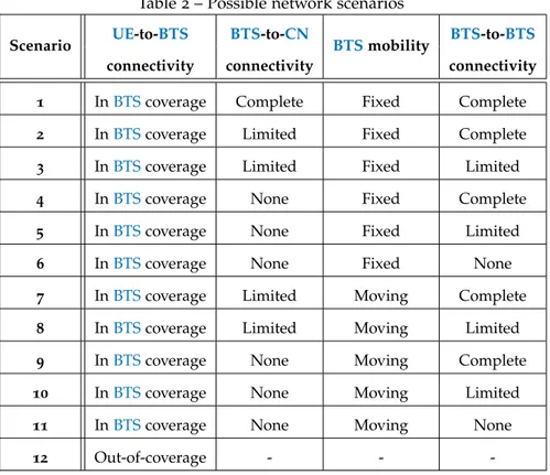
Table 2 – Possible network scenarios
Scenario UE-to-BTS BTS-to-CN BTSmobility BTS-to-BTS
connectivity connectivity connectivity
1 InBTScoverage Complete Fixed Complete
2 InBTScoverage Limited Fixed Complete
3 InBTScoverage Limited Fixed Limited
4 InBTScoverage None Fixed Complete
5 InBTScoverage None Fixed Limited
6 InBTScoverage None Fixed None
7 InBTScoverage Limited Moving Complete
8 InBTScoverage Limited Moving Limited
9 InBTScoverage None Moving Complete
10 InBTScoverage None Moving Limited
11 InBTScoverage None Moving None
12 Out-of-coverage - -
-grated devices) that requires a seamless access to the CN. Such a de-ployed network can support a variety of use cases; however, stringent requirements shall be considered when utilizing it forPS communica-tions, namely robustness, reliability, and non-prone to malfunctions and outages [14]. Despite aforementioned deployment requirements,
such fixedBTSsmay still not survive against unexpected events such as earthquake, hurricane, tsunami, and wildfire. Moreover, it may not cover distant lands due to costly deployment. Nevertheless, first re-sponders still need efficient PS communications in all circumstances even in harsh environments that require some large area opportunis-ticBTSsdeployments. In that sense, thePSwireless communications cannot rely solely on the planned network and must be able to ensure minimum services and sufficient level of quality when the planned network is not fully available or not possible to deploy [14]. Such a
network architecture could also answer military use cases that do not fit with the classical cellular architecture.
In view of the above limitations, Table2captures twelve scenarios
that can arise depending on four criteria: (i)UE-to-BTSconnectivity, (ii) BTS-to-CN connectivity, (iii) BTS mobility, and (iv) BTS-to-BTS
connectivity. These twelve situations are also illustrated in Figures2, 3,4and5. In the following, we go through these cases in more details.
— UE-to-BTS connectivity: In the nominal cases, users are under
BTS coverage (Scenario 1 to 11). When combined with all other ideal factors, Scenario 1 is the nominal and ideal case with planned and fixed BTS coverage andBTSs having complete access to the
2.2 network topologies 11
CN
BTS
1
Fixed BTS and relay Full backhaul access
PS / Mil Services BTS CN BTS 2
Fixed BTS and relays Limited backhaul access Full interconnectivity PS / Mil Services BTS CN BTS 3
Fixed BTS and relays Limited backhaul access Slow interconnectivity PS / Mil Services BTS UE UE UE UE UE UE UE UE UE UE UE UE UE UE UE UE UE UE relay relay relay Nominal Backhaul Link Slow
Backhaul Link Backhaul LinkSlow
Figure 2 – Network topologies - scenarios 1, 2 and 3.
CN
BTS
4
Fixed BTS and relay No backhaul access Full interconnectivity PS / Mil Services BTS CN BTS 5
Fixed BTS and relay No backhaul access Slow interconnectivity PS / Mil Services BTS CN BTS 6 Fixed BTS and relay No backhaul access No interconnectivity PS / Mil Services BTS UE UE UE UE UE UE relay UE UE UE UE UE UE relay UE UE UE UE UE UE relay
Figure 3 – Network topologies - scenarios 4, 5 and 6.
BTS CN PS / Mil Services 7 Moving BTS Limited backhaul access Full interconnectivity Moving BTS BTS CN PS / Mil Services 8 Moving BTS Limited backhaul access Limited interconnectivity UE UE UE UE UE Moving BTS UE UE UE UE UE Fast
interconnection Slow Backhaul Slow Backhaul
Figure 4 – Network topologies - scenarios 7 and 8.
Moving BTS Moving BTS 9 Moving BTS No backhaul access Full interconnectivity Moving BTS Moving BTS 10 Moving BTS No backhaul access Limited interconnectivity Moving BTS Moving BTS 11 Moving BTS No backhaul access No interconnectivity D2D 12 No BTS coverage UE UE UE UE UE UE UE UE UE UE Fast
interconnection interconnectionSlow
Figure 5 – Network topologies - scenarios 9, 10, 11 and 12.
CN that allows to provide services with no intermissions to in-coverage UEs (e.g., continuous link connectivity with operation center, monitoring, billing) [15]. Such scenario happens in the
covered cities and (sub)-urban environments where the network deployment has been previously designed and planned. However, users may be out-of-coverage of the service area or fail to maintain any connection toBTSsdue to their mobility (scenario 12). Hence, users may rely onProSebased onD2Dcommunications [16] with
12 s tat e o f t h e a r t a n d p r o b l e m s tat e m e n t
— BTS-to-CN connectivity: When the backhaul link (i.e., links be-tween BTS and CN) disruption or failure happens, the CN may not be fully accessible fromBTSs. If it can only provide some con-trol plane functionalities, i.e.,BTSscan still acceptPS UEs connec-tions but need additional mechanisms to provide data transporta-tions (e.g., local routing [17]), it is referred as limited BTS-to-CN
connectivity (scenarios 2 and 3). Otherwise, it is referred as un-availableBTS-to-CNconnectivity (scenarios 4, 5 and 6) and some localCNfunctionalities atBTSis required to servePS UEs. — BTS-to-BTS connectivity: We can observe that the BTS-to-BTS
connectivity does not necessarily rely on the backhaul connectiv-ity. For instance, a full connectivity between BTSs (scenarios 2 and 4) can allow to form a large network even with limitedBTS -to-CNconnectivity.1
Note that the limitedBTS-to-BTS connectiv-ity (scenarios 3 and 5) case can only exchange partial information between BTSsand may restrict certain features such as inter-BTS
handover.
— BTSmobility: MovingBTSscan be utilized in a dynamic fashion (e.g., during fight against forest wildfire or using vehicularBTS be-ing on land or at sea [18,19]). In such cases, it is difficult to
main-tain a good connectivity betweenBTSandCN(scenarios 7 to 11) and it is complicated to inter-connect these movingBTSsin terms of different areas (coverage region, propagation condition) and embedded equipments (dedicated or shared wireless backhaul). In that sense, the network topology will split and merge dynam-ically and it shall be maintained properly to provide the widest service area to covered UEs. Furthermore, the interference be-tween BTSswill become a performance-limiting factor when two
BTSsare getting closer and an interference management scheme is mandatory.
New solutions need to be developed to tackle aforementioned non-idealities of classical cellular networks.
2.2.2 Scenarios of reference
In the following, we consider two main scenarios to describe typical use cases.
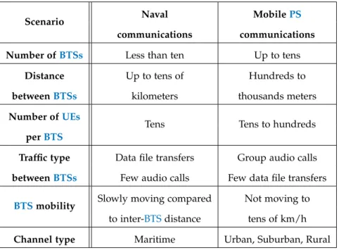
For naval communications, as we can see in Figure1, ships are
usu-ally sailing in small groups, except in aeronaval groups where there can be up to seven or eight ships at most. Distance between ships vary from a few kilometers to tens of kilometers. Information is shared di-rectly between ships to maintain the necessary operational awareness which may require large data file transfers. There are usually not
1. ThePerformance-Enhancing Proxy (PEP)in IETF RFC 3135 and RFC 3449 can
2.3 problem statement 13
many mobile UEs around ships but some may require high band-width to transmit real time videos or photos. Voice communications are currently handled by dedicated systems and usually restricted to each ship with few calls going from ship to ship.
For PS, communications are for the moment mostly voice commu-nications due to the lack of high data rate service. In situation of mobility without a fixed deployment, the number of involved BTSs
can vary from one to a few tens depending the area to cover. In these cases, transmissions are mostly voice group communications with potential records or transmissions to centralizedBTSsand head quarters.
We can summarize the considered scenarios and their characteris-tics in Table 3.
Scenario Naval MobilePS
communications communications
Number ofBTSs Less than ten Up to tens
Distance Up to tens of Hundreds to
betweenBTSs kilometers thousands meters
Number ofUEs
Tens Tens to hundreds
perBTS
Traffic type Data file transfers Group audio calls
betweenBTSs Few audio calls Few data file transfers
BTSmobility Slowly moving compared Not moving to
to inter-BTSdistance tens of km/h
Channel type Maritime Urban, Suburban, Rural
Table 3 – Considered scenarios
2.3 p r o b l e m s tat e m e n t
We have seen in sections 2.1.1and 2.1.2 that current military and PScommunication systems are not up to the requirements of new use cases, especially regarding maximum achievable data rates.
Moreover, we have seen in section2.2.1that several similar network
topologies can arise inPSand military use cases. However, as under-lined in Baldini et Al. [9] study and in section2.1.2, most PS
commu-nication systems are based on fixed deployed cellular networks and cannot support all these network topologies as they require a steady access to a commonCN.
Thus, we see that both PS and military authorities could benefit from new communication systems that would address their evolving
14 s tat e o f t h e a r t a n d p r o b l e m s tat e m e n t
needs (high data rates, low latency, etc.) and match these use cases (adaptability to various network topologies).
The goal of this study is to define a wireless communication sys-tem to cover the network centric scenarios (ranging from 1 to 11 in Table 2) that would provide better performance than current sys-tems presented in section 2.1.1 and 2.1.2. Such a system would al-low providing services to mobile users aroundBTSwithout requiring connectivity to other external entities, while aiming for the widest network coverage through BTSs interconnections to form a joint au-tonomous network or several disjoint auau-tonomous networks. Note that while our initial targeted use cases are related to thePSand military communications requiring emergency or opportunistic deployments, such solution remains applicable to other use cases, e.g., moving ve-hicular,ITS, drone networks,UAVcommunications, etc. [13,18].
2.3.1 High level requirements
Based on aforementioned scenarios, an eligible solution shall be capable of dealing with all related non-idealities. Hence, we provide several high-level requirements regarding the system architecture and the required features.
Firstly, eachBTSshould provide service to its localUEseven when it is isolated, i.e., not connected to other BTSs or to the commonCN. This means that eachBTSshall be an autonomous node and must at minimum incorporate the following components and functions to be able to able to provide services in autonomy:
(a) A radio stack to serve localUEsas aBTS;
(b) A subset of CN entities to provide policy control, local UEs
mobility management, authorization and authentication among the others;
(c) A set of services/applications to allow for the minimum re-quired services (i.e., voice, location, etc.) to be available at servedUEs.
Secondly, we aim to efficiently and seamlessly interconnectBTSsin order to expand the network and to create an autonomous network. An autonomous network is a network that integrates self-organizing features in that it should detect, configure and maintain connection with new joining nodes to provide the best performance in all situ-ations regardless of the mobility of nodes. Moreover, it should not rely on any entity external of the network to provide its services. Cre-ation of an autonomous network is an enabler of several use cases in military communications such as ship-to-ship communications pre-sented in section2.1.1. Thus, some additional elements and functions
2.3 problem statement 15
(d) A wireless communication interface to establish inter-BTS con-nections;
(e) NeighboringBTSsdetection and connection mechanisms to en-able network split and merge;
(f) Self-reconfiguration capability to dynamically adapt to network topology;
(g) Interference management schemes to limit interference impact on UEsas well asBTSs;
(h) Connections betweenCNs that are hosted by differentBTSsto enable seamless inter-CNor inter-Mobility Management Entity
(MME)handover;
(i) An efficiently inter-BTStraffic routing mechanism to route traf-fic in the network;
(j) Cooperation between services/applications of different network nodes to enable the network-wide service.
To sum up, these requirements are mandatory to build and oper-ate the envisioned autonomous network that provides the required services with sufficient quality for PSand military users.
3
D E S I G N C O N S T R A I N T S A N D R AT C H O I C EIn the previous chapter, we defined the high level requirements to be matched by a solution that would answer the considered use cases for military and PS communications. In this chapter, we dis-cuss briefly on the external constraints applying to communication systems for military andPSuse cases before discussing on the choice of theRATsfor the solution.
3.1 e x t e r na l c o n s t r a i n t s
Additionally to the high-level requirements regarding the required features drawn in section2.3.1, thePSand military authorities as well
as other organizations that require similar services will face other con-straints when deploying the solution. These concon-straints are external to the aforementioned scenarios but are essential to enable the solu-tion for autonomous network.
Firstly, the constraint on the cost of the solution shall minimize the requirement ofCAPEXandOPEX. To reduce theCAPEXandOPEX, infrastructure sharing is viewed as a beneficial approach to enable the national PS network deployment [20]. In that sense, a solution that
only has limited hardware infrastructure requirement and integrates automatic procedures for their exploitation such as self-configuration, self-organization and self-healing is highly-anticipated.
Secondly, another constraint comes regarding the radio spectrum access and can be severely dimensioning. Due to a high utilization of the available spectrum, nowadays only few frequency bands and nar-row bandwidth are available to enable thePScommunications. Note such available bands are managed by the state regulation and can be limited and different from country to country. Moreover, the known
Industrial, Scientific, and Medical (ISM) frequency bands can be
uti-lized freely but suffer from power limitation and high interference. Furthermore, in some use cases such as military operations, new wire-less systems shall not disrupt previously deployed systems that are still in use which may also limit the available frequency bands even with legally access to several frequency bands. For instance, navy sur-face ships are equipped with several radio frequency equipment for communication but also for detection and surveillance such as radar and radio detectors which occupy part of the radio spectrum.
In summary, a solution shall firstly be designed to cover the use cases in section2.2.1and fulfill the aforementioned high-level
require-ment in section 2.3.1. Moreover, its cost shall be minimized in terms
18 d e s i g n c o n s t r a i n t s a n d r at c h o i c e
of required hardware resource. Lastly, it shall be capable of deal-ing with heterogeneous frequency band availability and reaches high spectral efficiency.
Thus, we target to design a wireless communication system that would allow the creation of variousBTSsnetwork topologies while supporting mobiles entities and requiring minimum hardware and frequency resources.
3.2 r at o f au t o n o m o u s n e t w o r k
Before designing a proper solution, we need to firstly select the underlyingRATsto enable the solution.
Baldiny et Al. survey from 2013 [9] compares the following
com-munication systems for PS use: Analog Professional Mobile Radio
(PMR); Digital Mobile Radio (DMR); P25; TETRA V.1; TETRA V.2;
TETRAPOL;Global System for Mobile communications (GSM)/
Gen-eral Packet Radio Service (GPRS)/Universal Mobile
Telecommunica-tion System (UMTS)/ 3G;LTE; Satellite Networks; WiFi /Worldwide
Interoperability for Microwave Access (WiMAX); Ad-hoc Networks;
Marine Communications; Avionics Communications. In their conclu-sion, the authors notice that "LTE has emerged as the technology of choice and future solution in PS". Indeed, 4GLTE is designed with a number of interesting properties, namely high spectral efficiency, frequency flexibility, large coverage area through high power support and native support of variety ofInternet Protocol (IP)-based services thanks to the flatIP architecture. Ferrus et Al. [21] come to the same
conclusion, noting that LTE has reached the required maturity level and wide adoption to replace the previous PS communication sys-tems. However, both articles observe thatLTEfaces several challenges to be adopted as the nextPSwireless access technology as it is initially designed for commercial markets.
However, some improvements have been achieved since 2013.3GPP
has started to address specific PS requirements from Release 11 due to growing demand for PS communications as we will show in the next subsection, andLTEhas been officially selected as the nextRAT
for PS wireless access in the USA [22]. Moreover, LTE will serve as
the technology basis for future 5G systems and should continue to evolve and to remain in use for commercial and private networks for a long period thanks to it wide deployment and co-existence features for use in unlicensed bands such asLicensed Assisted Access (LAA). Based on these considerations, we only focus onLTEas the main candidateRATto provide the service on access link toPSand mili-tary mobile users.
3.2 rat of autonomous network 19
3.2.1 LTE state of the art
TheLTEterm is mainly used to refer to theEvolved Packet System
(EPS) while it originally corresponds only to the Radio Access
Net-work (RAN)part of the EPS, called the E-UTRAN that corresponds
to the deployedBTSs[23]. TheEPS, that we will callLTEhereinafter,
is the new terrestrial cellular network specificied by the 3GPP to
re-place 2G and 3G cellular systems as shown on Figure6.
IS-95A
CDMA cdma2000IS-95C
E-GPRS EDGE W-CDMA HSDPA HSUPA HSPA+ IS-95B CDMA HSCSD LTE-Advanced Rel - 10 ++ WiMAX2 802.16m PDC IS-136 TDMA GSM iMode GPRS TD-SCDMA EDGE Evolution 1xEV-DO Release 0, A, B LTE Rel - 8/9
802.11b 802.11a 802.11g 802.11n 802.11ac802.11ad 802.16d
Fixed WiMAX WiBRO
802.16e Mobile WiMAX 2G 2.5G 3G 3.5G 3.9G IMT-Advanced4G Commercially 4G 4G+
Figure 6 – Evolution of cellular system standards.
The first version ofLTEwas released in 2008 in3GPP Release 8. It
did not meet the requirement fromInternational Telecommunication
Union (ITU) to be qualified as a 4G RAT, but Release 10 finalized
in 2011 did. LTE was designed with several goals in mind: high spectral efficiency; high maximum data rate; low latency; bandwidth and frequency flexibility. This, alongside some general motivations to ensure competitiveness of 3GPPsystems [23]:
— Provide higher data rates and better quality of service than pre-vious cellular systems
— Deliver a packet switched optimized system
— Answer continuous demand for cost reduction (both CAPEX
andOPEX)
— Deliver a low complexity system
— Avoid unnecessary fragmentation of technologies for paired and unpaired band operation
20 d e s i g n c o n s t r a i n t s a n d r at c h o i c e
LTE architecture
LTEis a cellular communication system by design. Figure7presents
its nominal architecture.
It relies on fixed set of BTS, called eNB, that form the E-UTRAN
and are used to wirelessly serve mobile entities (UEs) through the
Uu interface. EacheNB is solely responsible of managing the radio resources it can allocate to its multiple connectedUEson theUu inter-face. TheUuinterface is the only interface on which theLTEnetwork is implementing all network layer starting from the physical layer up to providing an IP connectivity to the UEs. Indeed, all other inter-faces represented on Figure7(S1, S5, S6a, S7, S8, S11, X2) are taking
place on top of IP and can rely on any underlying wired or wire-less technology that would provide an IP connectivity given some minimum latency and/or data rate requirements. The eNBsare con-nected to the CN, named EPC, through the S1 interfaces. Moreover, theeNBscan be connected directly together through the X2 interface which can be used for instance to ease handover of UEs. We stress that the X2 interface is a high layer interface taking place over an ex-isting IP connectivity throughStream Control Transmission Protocol
(SCTP) and GPRS Tunneling Protocol (GTP) tunnels established
be-tweeneNBs. It cannot be used without any pre-existing physical and higher layer interfaces bringing IPconnectivity betweeneNBs.
The EPC is composed of several elements that are used to man-age the control and user planes of UEs to provide end-to-end
com-E-UTRAN
EPC
eNodeB
eNodeB
HSS
MME
PCRF
P-GW
S-GW
eNodeB
S7 S5-S8 S6a S11 S1-MMES1-MME S1-MME S1-U S1-U S1-U
SGi X2 X2 X2
UE
UE
UE
UE
UuUE
Uu Uu Uu Uu3.2 rat of autonomous network 21
munications, authentication, handover and billing among other fea-tures. TheMME is the key control node for theLTE access network, supporting security procedures for UE and network authentication, ciphering and integrity protection. It handles all signaling proce-dures related to session establishment and management as well as associated QoS. It is part of the tracking area update process that provides user location knowledge to the network for incoming ses-sions. The MME is connected through S6a interface to the Home
Subscriber Server (HSS). The HSS is responsible for authenticating
and authorizing user access via forming the database that contains user subscription and authentication context (through International
Mobile Subscriber Identity (IMSI) andMobile Subscriber Integrated
Services Digital Network Number (MSISDN)) and transmitting the
security information and authentication keys to the MME and eNB.
TheServing Gateway (S-GW)andPacket Data Network Gateway
(P-GW) allows terminating UE data plane bearers. The P-GW is the termination point toward external packet data networks such as In-ternet through the SGi interface.
Finally, thePolicy and Charging Rules Function (PCRF)server make policy decisions based on the network operator rules and manages charging of service data flows if necessary.
LTE standards development for PS
The simmering interest of public authorities inLTEfor public-safety use have encouraged 3GPP to tackle this subject. Especially,
signifi-cant standardization activities have been conducted after the creation of theFirst Responder Network Authority (FirstNet)in theUSA. As it is illustrated in Figure8, the first work dedicated onPSwas launched
Release 11 Release 12 Release 13 Release 14 High Power UE
(band 14) 36.521 36.837
Mission Critical Video 22.281 22.879 23.281 24.281 24.581 26.281 Mission Critical Data 22.282 22.880 23.282 24.282 24.582 Mission Critical Push To Talk 22.179 23.179 23.379 24.379 24.380 24.980 26.179 26.879 26.989 33.179 33.879 Group Communications 22.468 23.768 36.868 Isolated E-UTRAN 22.346 22.897 23.797 23.798 33.897 Proximity-based Services 22.803 23.303 23.703 32.844 33.833 Features Mission Critical Services 22.280 23.280 23.780 33.180 33.880 Mission Critical Services 24.481 24.482 24.483 24.484
22 d e s i g n c o n s t r a i n t s a n d r at c h o i c e
in 3GPP Release 11 along with the introduction of high power
de-vices operating in Band 14 (which is used in USA and Canada for
PS) and extending the possible coverage servicing area. Since then, several work items have been defined in Release 12 and later to study and address the specific requirements of a broadband PS wireless network.
Nevertheless, the gaining momentum ofLTEnetworks around the globe has relied on its architecture to provide packet-based network services which are independent from the underlying transport related technologies. A key characteristic of this architecture is the strong dependency of every BTS (also known as eNB) on the packet core network (also known asEPC) for all the type of services that are pro-vided to the covered UEs. However, this feature prevents UEsfrom a seamless communication service when an eNB is getting discon-nected of theEPC. Thus,eNB service to theUEsis interrupted even for local communications which is essentially required by first respon-ders. To tackle the aforementioned shortcoming,3GPPhas launched
two series of work items: the first one refers to device-to-device com-munications for enablingProSe, and the second one refers to the con-tinuity of service for PS UEs by the RAN and eNBs in the case of backhaul failure for enabling operation on “IsolatedE-UTRAN”.
As it has been defined in Technical Specification (TS) 22.346, Iso-latedE-UTRANaims at the restoration of the service of one eNBor a set of connected eNBs without addressing their backhaul connectiv-ity. Therefore, IsolatedE-UTRANoperation focuses on adapting to the failure of the connectivity to theEPC and maintaining an acceptable level of network operation in three cases: “no backhaul” case, “lim-ited bandwidth signalling only backhaul” case and “lim“lim-ited band-width signalling and user data backhaul” case (TS22.346). Addition-ally, in the case when there is no coverage from the wireless cellular network or when it is no longer present due to unexpected disaster, IsolatedE-UTRANcan take place on top of Nomadic eNodeBs
(NeN-odeBs) deployments. NeNodeBs are intended for PS use providing
complementary coverage or additional capacity where service was previously unavailable. In all cases, the goal of Isolated E-UTRAN
Operation for Public Safety (IOPS)is to maintain the maximum level
of communications for public safety users and TS22.346 defines the associated requirements. It should support voice and data commu-nications, MCPTT,ProSeand group communications for PS UEs un-der coverage as well as their mobility between BTSs of the Isolated
E-UTRAN, all while maintaining appropriate security (TS33.897).
Subsequent to TS 22.346, Technical Report (TR) 23.797 provides an answer to the “no backhaul” IOPS case relying on the availabil-ity of a local EPC co-located with an eNB or on the accessibility of a set of eNBs. If an eNB cannot reach such local EPC, it must re-ject UE connection attempts. PS UEs should use a dedicated
Uni-3.2 rat of autonomous network 23
versal Subscriber Identity Module (USIM)application for
authentica-tion and use classicalUuinterface to connect to theseIOPSnetworks. However, the aforementioned solution does not address issues on scenarios related with limited backhaul connectivity. Moreover, re-quirements on the inter-eNBlink connectivity are not specified, even though the operation for group of inter-connectedeNBs is defined.
LTE network topologies
In nominal condition, LTE is used to deploy a nationwide broad-band wireless network that relies on fixed eNBs to provide planned coverage to UEs through the Uu interface as shown in Figure 9.(1).
Such topology can be mapped to the scenario 1 in Table 2. All these
plannedeNBscan have full access to theEPCthrough backhaul links without any interruptions.
Figure 9.(2) extends the normal one-hop case (i.e., UE↔ eNB) to
the two-hop case utilizing LTErelay node (i.e., UE ↔ relay ↔eNB) with the new Un interface towards eNB. The Un interface and relay node is firstly standardized in 3GPP Release 10. However, relays
can be frequency inefficient when handling local communications as the data has to go through the Donor evolved Node B (DeNB) to reach centralizedEPC as shown on Figure9.(2). Moreover, these two
aforementioned topologies do not handle any mobility ofBTSorCN
and thus can not cover all scenarios in Table 2, i.e., no common CN
access case (scenario 2 to 6) or mobileBTScases (scenario 7 to 11). To specifically address somePSscenarios, we have seen that3GPP
defined the IsolatedE-UTRANconcept andNeNodeBas shown in Fig-ure 9.(3) [24]. Hence, such topology can be mapped to the scenarios
with no commonCNconnectivity, i.e., scenario 1 to 6 in Table2.
Nev-ertheless, it can solely serve local UEsand can not establish any
con-UE eNodeB UE 1 – Nominal architecture UE eNodeB EPC UE eNodeB UE relay UE EPC UE UE UE eNodeB + local EPC functions
2 – Relay Self Backhauling (two hops)
3 – Isolated E-UTRAN e2NB e2NB e2NB e2NB e2NB UE UE UE UE UE UE
4 – Envisionned LTE Mesh architecture
eNodeB + +
Figure 9 – Topologies based on standard LTE BTS (1,2,3) and the envisioned LTE network (4).