Wheelchair pushrim kinetics measurement: a
1method to cancel inaccuracies due to pushrim
2weight and wheel camber
3Félix Chéniera,b*, Rachid Aissaouib,c, Cindy Gauthierb,d, Dany H. Gagnonb,d 4 aDepartment of Physical Activity Science, Université du Québec à Montréal 5 bPathokinesiology Laboratory, Centre for Interdisciplinary Research in Rehabilitation of Greater Montreal (CRIR)- 6 site Gingras-Lindsay Rehabilitation Institute of Montreal 7 cDepartment of Automated Manufacturing Engineering, École de technologie supérieure, Montréal 8 dSchool of Rehabilitation, Faculty of Medicine, University of Montreal 9 *Corresponding author: [email protected] 10
Published as a regular paper in Medical Engineering and Physics.
11Author’s final manuscript. For the final edited copy, please follow this link :
12http://dx.doi.org/10.1016/j.medengphy.2016.12.002
13
14
Abstract
15 The commercially available SmartWheelTM is largely used in research and increasingly used in clinical practice 16 to measure the forces and moments applied on the wheelchair pushrims by the user. However, in some 17 situations (i.e. cambered wheels or increased pushrim weight), the recorded kinetics may include dynamic 18 offsets that affect the accuracy of the measurements. In this work, an automatic method to identify and cancel 19 these offsets is proposed and tested. 20 First, the method was tested on an experimental bench with different cambers and pushrim weights. Then, the 21 method was generalized to wheelchair propulsion. Nine experienced wheelchair users propelled their own 22 wheelchairs instrumented with two SmartWheels with anti-slip pushrim covers. The dynamic offsets were 23 correctly identified using the propulsion acquisition, without needing a separate baseline acquisition. A 24 kinetic analysis was performed with and without dynamic offset cancellation using the proposed method. The 25 most altered kinetic variables during propulsion were the vertical and total forces, with errors of up to 9 N 26 (p<0.001, large effect size of 5). 27 This method is simple to implement, fully automatic and requires no further acquisitions. Therefore, we 28 advise to use it systematically to enhance the accuracy of existing and future kinetic measurements. 29 Keywords: Instrumented wheels, Wheelchairs, SmartWheel, Signal processing, Kinetics, Biomechanics. 3031
Nomenclature
32𝑨
3×6 dynamic offsets identification matrix
𝒃
6×1 calibration vector for the SmartWheel’s regression equations
𝒄
Force channels (6×1 vector)
𝒄
!Force channels at power-on (6×1 vector)
𝒇
Real pushrim kinetics (6×1 vector)
𝒇
ofs !Dynamic offsets (6×1 vector)
𝒇
SWMeasured pushrim kinetics (6×1 vector)
𝑱
! !6×6 matrix that translates force channels into the global reference frame
𝑱
!6×6 matrix that translates load cell forces into pushrim kinetics
𝑴
6×6 calibration matrix for the SmartWheel’s regression equations
𝒒
!1×3 state vector for the dynamic offsets identification
𝑹
(!)6×6 rotation matrix that translates the pushrim kinetics into the global reference
frame
𝑺
6×6 diagonal sensitivity matrix that translates force channels into load cell forces
𝒘
Pushrim weight (6×1 vector)
𝜃
Rear wheel angle
𝝉
Load cell forces (6×1 vector)
1 Introduction
33 Wheelchair propulsion is a tedious task that leads to the development of upper limb secondary 34 musculoskeletal impairments (SMI) over time in more than half of manual wheelchair users [1–4]. Extensive 35 research was conducted in the last decade to reduce the high prevalence of SMI. One key innovation is the 36 SmartWheelTM instrumented wheelchair wheel, developed by the Human Engineering Research Laboratory in 37 Pittsburgh [5]. Since it became available, the SmartWheel allowed the recording of the three forces and three 38 moments applied by the user on the pushrims during wheelchair propulsion, which strengthened the level of 39 evidence on the impact of the wheelchair propulsion technique and positioning on the development of SMI [6– 40 9]. This new evidence led the Consortium for Spinal Cord Medicine to formulate recommendations for 41 clinicians to instruct users to minimize the force and the rise of force they apply on the pushrims [10]. As this 42 force can be easily measured using an instrumented wheel, the SmartWheel has been implemented in a 43 growing number of clinical sites since 2008 [11]. 44 The SmartWheel is functionally identical to a gait force plate: pushrim kinetics is measured by a combination 45 of six load cells and is reported into a global reference frame located at the wheel hub center. However, the 46 load cells cannot be zeroed statically like a gait force plate because the wheel rotates relative to the gravity 47during manual wheelchair propulsion. Therefore, as the wheel turns, the weight of the handrim causes 48 dynamic offsets in the load cell readings, as a function of the wheel angle. 49 Such dynamic offsets were observed previously in other work. In 1998, Wu et al. [12] presented an 50 instrumented wheel and recorded the pushrim kinetics as the wheel turned with no external force applied on 51
the pushrim. They showed that for all velocities, dynamic offsets were present on the 𝐹x and 𝐹y signals and
52 were very well-modelled by sinusoidal signals. Woods et al. [13] also observed oscillating offsets on 𝐹x and 𝐹y, 53 along with static offsets on the other forces and moments. They modelled the dynamic offsets as a 54 combination of splines before subtracting them from subsequent recordings. 55 A similar method approach was proposed by Sauret et al. [14] and Dabonneville et al. [15], who modelled the 56 dynamic offsets as Fourier polynomials. However, instead of subtracting these offsets from the pushrim 57 kinetics, they subtracted them from the raw force channel data. Therefore, this approach requires (1) 58 calibration information to convert the force channels into pushrim force and moments, and (2) raw force 59 channel data, which may limit its application on past acquisitions where raw force channel data or calibration 60 information may have been discarded. 61 For all these experimental prototypes, the existence of dynamic offsets and their cancellation method were 62 well-documented. However, it seems that the commercial SmartWheel is not prone to such dynamic offsets. 63 The reason for this resides in a different approach to convert the raw force channel data in pushrim kinetics. 64 The SmartWheel does not require a baseline trial, but requires in-factory calibration values for a given 65 pushrim weight and a given wheel camber. Using these calibration values, the dynamic offsets can be 66 estimated as a function of the wheel angle, and are directly cancelled during propulsion. However, because 67 calibration values are dependent on pushrim weight and wheel camber, the recorded kinetics may be 68 inaccurate when wheel camber is modified or when weight is added to the pushrim. The first condition 69 (cambered wheels) is encountered with users of an ultralight wheelchair who want the benefit of the wider 70 base of support and seated stability, manoeuvrability and ergonomics provided by cambered wheels [16,17]. 71 The second condition (increased pushrim weight) happens, for example, when using an anti-slip pushrim 72 cover to optimize grip between the users' hand and the pushrim. As an example, the use of a commercial Q-73
Grip pushrim cover (Out-Front, Mesa, AZ, USA), a neoprene shell superposed to the existing pushrim and 74 weighing about 570 grams, facilitates manual wheelchair propulsion among persons with limited hand 75 function. Since both conditions may arise in clinics, the validity of the measured kinetic variables under these 76 conditions must be verified. Moreover, if corrections are required, then these corrections must not require 77 additional manual processing, either in a clinical or research context. 78 The first part of this study aims to measure the effects of wheel camber and pushrim weight on kinetic 79 measurements and to propose a method to cancel these effects. We hypothesized that (1) cambering the rear 80 wheels camber and/or adding weight to the pushrims will introduce dynamic offsets larger than the reported 81 SmartWheel measurements uncertainty [18], and (2) that identifying, then subtracting these offsets, will 82 reduce the error below this uncertainty. 83 The second part of this study aims to generalize the proposed method to actual wheelchair propulsion data 84 recorded at self-selected speed on level ground in a natural environment. We hypothesized that (1) the 85 dynamic offsets introduced by pushrim weight or wheel camber will be identified directly from the propulsion 86 acquisition, without needing a separate baseline acquisition, and (2) that correcting the recorded kinetics has 87 a significant impact on typical outcome measurements such as the minimal, mean and maximal values of 𝐹x, 𝐹y, 88
𝐹z, 𝑀x, 𝑀y, 𝑀z and their vectorial sum 𝐹tot, 𝑀tot. 89
2 Methods – Part 1 on an experimental bench
902.1 Material
91 A generic wheelchair (Astra, Orthofab Inc., Québec, QC, Canada) without wheel camber was instrumented with 92 one 24-inch instrumented wheel (SmartWheel, Out-Front, Mesa, AZ, USA) such as the one presented in Fig. 1, 93 on the right side. The wheelchair frame was fixed on a support so that the wheels did not touch the ground. 94 One side of the support was installed on an elevator platform so that the wheelchair could be inclined at 95 specific angles, thus simulating different wheel cambers (Fig. 2). The simulated camber 𝛼 was calculated using 96the known width 𝑤 of the support base and the height ℎ of the elevator: 𝛼 = asin (ℎ/𝑤). During the 97
acquisition, one trial was completed without added weight at the pushrim ( i.e., no cover) and one trial was 98 completed with an increased pushrim weight since a Q-Grip pushrim cover (Outfront, Mesa, AZ, USA) was 99 used. 100
2.2 Data acquisition
101 The elevator platform was adjusted to reach three simulated camber angles: 102 • 0° : no camber; 103 • 10° : a typical maximal value with standard ultralight wheelchairs; 104 • 20° : typically used with sporting wheelchairs. 105 For each of these angles, an acquisition was made with and without the Q-Grip rubber pushrim cover, for a 106 total of six conditions. One trial was performed per condition. The instrumented wheel was powered on 107 immediately before each acquisition. After power-on, the operator initiated a rotation of the wheel of about 108 0.5 turn/second (which corresponds to a linear velocity of 1 m/s), and then let the wheel decelerate by itself. 109 The wheel velocity was estimated using a chronometer. The wheel was pushed by the tire and not by the 110 pushrim, therefore no external force was applied on the pushrim during all the acquisitions. For all 111 acquisitions, instrumented wheel data (forces, moments and wheel rotation angle) were recorded and 112 sampled at 240 Hz. 1132.3 Data processing
1142.3.1 Effect of wheel camber and pushrim weight on dynamic offsets
115 Presented in the appendix, a complete kinetic analysis of the SmartWheel instrumented wheel demonstrates 116how pushrim weight and wheel camber theoretically add dynamic offsets 𝒇ofs ! to the recorded pushrim
117
kinetics. To verify this assertion experimentally, the pushrim kinetics measured on the experimental bench 118
(𝐹!, 𝐹!, 𝐹!, 𝑀!, 𝑀!, 𝑀!) were plotted without further processing, along with their vectorial sums 𝐹tot=
119
𝐹!!+ 𝐹!!+ 𝐹!! and 𝑀tot= 𝑀!!+ 𝑀!!+ 𝑀!!, for all six conditions. The root-mean-square (RMS) value of 𝐹!, 𝐹!,
𝐹!, 𝑀!, 𝑀!, 𝑀! was also calculated and compared to the SmartWheel's RMS uncertainty of 𝑈!!= 𝑈!! = 2.2 N, 121 𝑈!!= 0.93 N, 𝑈!!= 𝑈!!= 0.09 and 𝑈!! = 2.24 Nm as reported by Cooper et al. [18]. 122
2.3.2 Offset identification and cancellation
123 Still from the analysis in the appendix, the real pushrim kinetics 𝒇 can be obtained by subtracting the dynamic 124offsets 𝒇ofs(!) from the recorded pushrim kinetics 𝒇SW: 125
𝒇 = 𝒇
SW− 𝒇
ofs !(1)
126
where vectors 𝒇, 𝒇SW and 𝒇ofs ! are 6×1 vectors in the form 𝐹x 𝐹y 𝐹z 𝑀x 𝑀y 𝑀z !. These offsets
127
correspond to a sinusoidal function of wheel angle 𝜃 and therefore can be modelled as: 128
𝒇
!"# !
= 𝒒
!𝑨
!(2)
where 𝒇ofs ! is a 6×1 vector in the form 𝐹x 𝐹y 𝐹z 𝑀x 𝑀y 𝑀z!, where 𝒒! = [sin 𝜃 cos 𝜃 1] and
129
where 𝑨 is a 3×6 matrix to be identified. 130
Therefore, the dynamic offsets 𝒇ofs(!) must first be identified by estimating matrix 𝑨. To this effect, we use 131 baseline data where no force is applied on the pushrim (𝒇 = 𝟎). In this condition, Eq. (1) and (2) become: 132
𝟎 = 𝒇
SW− 𝒒
!𝑨
!(3)
133 Matrix 𝑨 can be estimated from these baseline data using a least-square regression of Eq. (3) [19]: 134𝑨 = 𝑸
!𝑸
!!𝑸
!𝑭
SW(4)
135 where: 136 • 𝑸 is an 𝑁×3 matrix where line 𝑖 corresponds to 𝒒(!) evaluated on sample 𝑖. 137• 𝑭SW is an 𝑁×6 matrix where line 𝑖 corresponds to 𝒇SW! recorded on sample 𝑖. 138 • 𝑁 is the number of data samples. 139 Cancelling dynamic offsets using such an identification process is illustrated in Fig. 3 (a). 140 Insert Figure 3 here. 141 To test this offset cancellation process, matrix 𝑨 was estimated in the six bench conditions following Eq. (4), 142 then the identified dynamic offsets were subtracted from the same recorded kinetics following equations (1) 143 and (2). The RMS values of the corrected kinetics were calculated. 144
3 Methods - Part 2 with participants
1453.1 Participants
146 Nine experienced wheelchair users whose demographics are summarized in Table 1 participated in this study. 147 Any person using a manual wheelchair as their primary mean of mobility (i.e., at least 4 hours per day) could 148 participate in this study. Potential participants who had debilitating pain, musculoskeletal impairments or any 149 other cognitive condition or visual impairment that can limit the performance of experimental tasks were 150 excluded from the study. Before the acquisitions, the participants answered two relevant questions of the 151 Wheelchair User’s Shoulder Pain Index (WUSPI) in the context of the present study: Task 5 - pushing 152 wheelchair for 10 minutes or more; Task 6 - pushing up ramps or inclines outdoors [20] to ensure the absence of 153 important shoulder pain when propelling their wheelchair. They were excluded if they answered more than 154 6/10 for either task. The participants underwent a single experimental data collection at the Pathokinesiology 155 Laboratory of the Centre for Interdisciplinary Research in Rehabilitation of Greater Montreal (CRIR), site 156 Gingras-Lindsay Rehabilitation Institute of Montreal (IRGLM). The experimental protocol was approved by 157 the research ethics committee of the CRIR, reference number CRIR-943-0314. All participants approved and 158 signed the information and consent form before participating in the study. 159 Insert Table 1 here. 160
3.2 Material
161 All participants used their own ultralight aluminium or composite wheelchairs that were instrumented 162 bilaterally with two 24-inch SmartWheels. All participants normally used rear wheels with a diameter 163 between 23 and 25 inches, thus limiting their adaptation to a different diameter. Their own wheel cambers 164 were not altered and were computed using 3 specific points collected within the wheel plane with a calibrated 165 optoelectronic probe and a four-cameras Optotrak system (Northern Digital Inc., Waterloo, ON, Canada). A Q-166 Grip pushrim cover was installed over both pushrims prior to powering on the instrumented wheels. The 167 acquisitions took place in an institutional hallway with standard industrial vinyl floor covered with a rubber 168 surface similar to the one found on commercial motorized treadmill belts. The rubber surface had a thickness 169 of 3 mm, a width of 1 m and a length of 25 m. A total of 20 strokes are typically needed to travel this distance. 1703.3 Data acquisition
171 Two acquisitions were completed for each participant. The first one was a baseline trial: a research associate 172 pushed the wheelchair along the hallway at a natural walking speed of about 1 m/s. Participants did not touch 173 the wheels during this trial. The second acquisition was a propulsion trial where the participants were asked 174 to propel at 1 m/s along the same hallway. The average wheeling speed was measured using a chronometer. If 175 necessary, the trial was repeated until the average velocity fell between 0.9 and 1.1 m/s. Only one baseline 176 and one propulsion data acquisition trial was analyzed per participant. 1773.4 Data processing
1783.4.1 Offset identification from propulsion data
179 If a baseline acquisition is unavailable, it is still possible to estimate matrix 𝑨 using propulsion data. To this 180 effect, we make the assumption that during typical level-ground propulsion, at least one half of the propulsion 181 time corresponds to recovery phases, where no force is applied on the pushrim [9]. By identifying the 182 recovery phases in the propulsion trial, we can then use only these samples to estimate 𝑨. 183We show in the appendix that the measured moment 𝑀z is theoretically free of dynamic offsets. As a 184 consequence, the measured moment 𝑀z is variable during the push phase but mostly constant during the 185 recovery phase. To isolate the samples corresponding to recovery phases, the highest or lowest moment 𝑀z 186
relative to median 𝑀z is iteratively removed until all the remaining 𝑀z values are contained within an
187 interval of 2.24 Nm corresponding to the uncertainty of 𝑀z [18]. Reaching this condition indicates that all push 188 phases were removed from the signal. Correcting 𝒇SW using this method is shown as a flowchart in Fig. 3 (b). 189 To test this offset identification method, which is presented as a flowchart in Fig. 3 (a), a first dynamic offsets 190
vector 𝒇ofs1 ! was calculated for each participant using the baseline acquisition, as previously done on the
191
experimental bench. Then, a second offset vector 𝒇ofs2 ! was calculated using the propulsion acquisition, as 192
indicated in the flowchart of Fig. 3 (b). The root-mean-square difference (RMSD) between 𝒇ofs1 ! and 𝒇ofs2 !
193 was calculated for each participant over a wheel angle range of 𝜃 ∈ [0 ≤ 𝜃 < 2𝜋]: 194
RMSD 𝒇
ofs1 !, 𝒇
ofs2 ! !=
1
2𝜋
𝒇
ofs1 !!− 𝒇
ofs2 ! ! !𝑑𝜃
!! !(5)
195 where 𝑖 ∈ 1, 6 . 1963.4.2 Effect of the dynamic offsets on measured pushrim kinetics
197 The propulsion kinetics was analyzed following these conditions: 198 1. Original pushrim kinetics 𝒇SW without further processing; 199 2. Corrected pushrim kinetics 𝒇 with the offsets identified based on propulsion data. 200 The following kinetic data were computed for both conditions: 201• Average, minimal and maximal force on each axis (𝐹x, 𝐹y, 𝐹z, 𝐹tot= 𝐹x!+ 𝐹y!+ 𝐹z!), in N;
202
• Average, minimal and maximal moment on each axis (𝑀x, 𝑀y, 𝑀z, 𝑀tot= 𝑀x!+ 𝑀y!+ 𝑀z!), in Nm.
As start-up and steady-state kinetics is typically different [21], data were analyzed separately for start-up 204 (first push only) and for steady-state propulsion (average of pushes 4 to 10). Steady state was defined as 205 starting from the 4th stroke in accordance with the SmartWheel clinical software [22]. Push detection was 206
performed using a dual force-threshold of 10 N (grab) and 5 N (release) on 𝐹tot. These thresholds were
207 selected experimentally to maximize the push length while minimizing the false push detections. 208 The expected sample size was N=18 (9 participants × 2 instrumented wheels). The statistical significance of 209 the difference between the original and corrected pushrim kinetics was evaluated using Students’ paired t-210 tests with a significance value of 𝛼 = 0.05. The practical significance of the difference was reported using the 211 estimated effect size (Cohen’s d statistic). The effect size was interpreted as small (> 0.2), moderate (> 0.5) or 212 large (> 0.8) [23]. 213
4 Results
2144.1 Part 1 on an experimental bench
215Figure 4 shows the measured kinetics for the six bench acquisitions. When camber increased, 𝐹x, 𝐹y and 𝐹tot 216
variation increased from about ±1 N to about ±2 N. When a pushrim cover was used, 𝐹x, 𝐹y and 𝐹tot variation 217
increased from about ±1 N to about ±7 N and 𝑀!, 𝑀! and 𝑀tot variation increased from about ±0.1 Nm to
218 about ±0.3 Nm. In all cases, no variation should have been observed since no external force was applied on the 219 pushrim except the constant weight of the pushrim cover. 220 Table 2 shows the RMS kinetics for the same six acquisitions. The error introduced by wheel camber was 221 lower than the reported SmartWheel’s RMS uncertainty. The error introduced by the pushrim cover, however, 222
was higher than the SmartWheel’s RMS uncertainty for 𝐹!, 𝐹!, 𝑀! and 𝑀!. The mediolateral force 𝐹! and the 223
propulsion moment 𝑀! were not affected by either wheel camber or pushrim cover.
224
Insert Table 2 here.
225 Figure 5 shows the measured kinetics for the six same bench acquisitions after cancelling the dynamic offsets. 226 The offsets were effectively cancelled in all cases. Table 3 presents the corresponding RMS corrected kinetics, 227 which contrarily to Table 2 are lower than the SmartWheel’s RMS uncertainty for every six combinations of 228 wheel camber and pushrim weight. 229Insert Figure 5 here
230Insert Table 3 here
4.2 Part 2 with participants
231 Every participant performed a propulsion trial with both hands, for a total of 18 recorded datasets. Among 232 those datasets, two (from different users) were discarded because the users had one hand on the pushrim 233 during wheel zeroing upon start-up, which resulted in erroneous measured kinetics. The total number of 234 analyzed datasets was therefore N=16 (14 from 7 bilateral acquisitions and 2 from 2 unilateral acquisitions). 235 Wheel camber varied between participants from 0 to 9.4∘ with a mean and standard deviation of 3.6 ± 2.4∘. 236 Table 4 presents the RMS difference between the dynamic offsets identified using either baseline data or 237 propulsion data. For every force and moment, the difference was below the SmartWheel’s RMS uncertainty. 238Insert Table 4 here
239 Figure 6 shows the pushrim kinetics for a typical participant over the hallway: original, corrected using 240 baseline data, and corrected using propulsion data. Dynamic offsets can be observed during the recovery 241
phases in the original curves for 𝐹x, 𝐹y and 𝐹tot, and to a lesser extent for 𝑀x and 𝑀tot. These offsets were 242 cancelled successfully using either offset identification method. 243
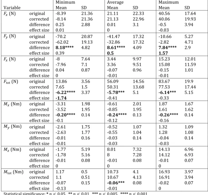
Insert Figure 6 here
244 Table 5 shows the minimum, average and maximum values for each measured kinetic variable during 245 propulsion start-up on the hallway. Significant differences were found between original and corrected values 246for the min, average and max values of 𝐹y (𝑝 < 0.001), 𝐹tot (𝑝 < 0.005), 𝑀x (𝑝 < 0.001), and for the average 247
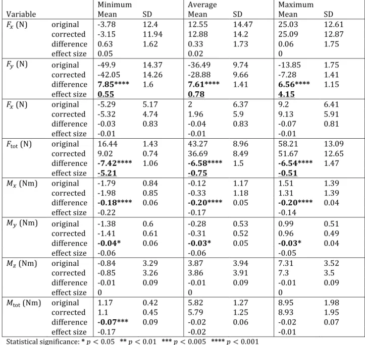
value of 𝑀tot (𝑝 < 0.005). The effect size was large (> 0.8) for max(𝐹y) and min(𝐹tot) with differences up to 248 7.8 N, and medium (> 0.5) for average(𝐹y) with a difference of 8.6 N. 249 Table 6 shows the same variables for steady state propulsion over the hallway. The results are similar: 250 significant differences were also observed for the min, average and max values of 𝐹y (𝑝 < 0.001), 𝐹tot (𝑝 < 251
0.001), 𝑀x 𝑝 < 0.001 , 𝑀y (𝑝 < 0.05) and for the min value of 𝑀tot (𝑝 < 0.005). The effect size was large (>
252
0.8) for max 𝐹y , min 𝐹tot with differences up to 7.4 N, and medium (> 0.5) for min(𝐹y), average(𝐹y), max(𝐹tot) 253 and average(𝐹tot). 254
Insert Table 5 and Table 6 here
5 Discussion
255 The first part of the present study aimed to test two distinct hypotheses: 256 1. Adding weight to the pushrim or cambering the wheels generates inaccuracies in the kinetics 257 measured by the SmartWheel; 258 2. These inaccuracies can be identified and cancelled from the recorded measures. 259The first hypothesis was confirmed with the bench acquisitions in Fig. 4, with clearly visible sinusoidal offsets 260 in every condition with cambered wheels or pushrim cover on. The second hypothesis was also confirmed in 261 Fig. 5 where all offsets were cancelled successfully in every condition after identifying and subtracting them. 262 While cambering wheels did generate dynamic offsets (Fig. 4), these offsets were below the reported 263 SmartWheel’s RMS uncertainty (Table 2); therefore, contrarily to adding weight to the pushrim, wheel 264 camber may not affect the measurement accuracy to a great extent. This being said, small dynamic offsets 265
were observed in 𝐹x and 𝐹y, even without a pushrim cover and with a 0∘ camber, and these offsets were
266 completely cancelled in Fig. 5. This emphasizes the interest in cancelling dynamic offsets systematically, even 267 when rear wheels are not cambered and when pushrim weight is not altered. 268 The second part of the present study also aimed to test two distinct hypotheses: 269 1. The dynamic offsets that were observed and cancelled in the bench experiment can also be identified 270 and cancelled in a real propulsion acquisition, without requiring an additional baseline acquisition; 271 2. Correcting the pushrim kinetics has a significant impact on minimal, mean and maximal values of 𝐹x, 272
𝐹y, 𝐹z, 𝐹tot, 𝑀x, 𝑀y, 𝑀z and 𝑀tot. 273
The first hypothesis was confirmed since the difference between the offsets 𝒇ofs1 ! obtained from baseline
274
data and the offsets 𝒇ofs2 ! obtained from propulsion data was found negligible (Table 4). Although some 275 dynamic offset cancellation approaches were described in existing literature [12–15], cancelling them without 276 a baseline acquisition was never proposed in the past. This new method was based on the theoretical proof 277 that 𝑀z, as recorded by the instrumented wheel, is free of dynamic offsets. This assumption was also verified 278 with both the bench data and the propulsion data: 𝑀! was near zero in every condition of Fig. 4, and the offset 279 cancellation did not alter 𝑀! values in Fig. 6 and Tables 5 and 6. 280 The second hypothesis was also confirmed since the dynamic offsets had an impact on the assessed kinetic 281 variables (Tables 5 and 6). However, not all variables were affected or equally affected by these offsets, as the 282
effect size was much larger for 𝐹y and 𝐹tot. As secondary calculations such as joint dynamics by means of 283
inverse dynamics and mechanical effective fraction of force (MEF) are dependant on an accurate 284
measurement of 𝐹y and 𝐹tot [8,24], it is therefore important to ensure that the recorded kinetics are free of 285 dynamic offsets when calculating such secondary variables. 286 Using propulsion data instead of an additional baseline acquisition provides three important advantages: 287 1. No additional baseline data is needed, reducing the required time to collect data in the presence of a 288 participant. 289 2. The identified dynamic offsets are trial-specific, which ensures an optimal offset cancellation 290 independently of the testing condition. 291 3. It allows secondary analysis of existing datasets where a baseline acquisition was not performed. 292
5.1 Clinical relevance
293 The clinical SmartWheel software automatically generates a report based on few pushes of level ground 294 propulsion. Therefore, the proposed method may not be applicable directly by the clinician until the software 295 implements it. 296 This being said, the clinician should be aware that using pushrim add-ons could generate systematic 297 measurement inaccuracies and should be avoided if possible. Otherwise, comparative measurements must at 298 least be done in the same conditions each time they are performed. Wheel camber is likely not a problem since 299 the inaccuracies it introduces are below the measurement uncertainty. 3005.2 Research relevance
301 For research application, the proposed method should be systematically used, especially when weight is 302 added on the pushrim. This method is fully automatic, simple to implement using common research tools such 303 as Matlab or Python, and also cancels potential offsets even at 0∘ without pushrim cover. 304 When assessing level ground propulsion at submaximal velocity on a low-resistance ground, the offsets 305 should be identified based on the propulsion data itself, as pictured in Fig. 3 (b). Otherwise, for example 306 propelling on a slope, on a highly resistive material such as thick carpet or gravel, or braking, they should be 307identified based on separate baseline data, as pictured in Fig. 3 (a), since the assumption that the user touches 308 the wheels less than 50% of the time may not be respected in these cases. 309
5.3 Limits of the study
310 To isolate the samples corresponding to the recovery phases, the assumption that the user touches the wheels 311 less than 50% of the time must be respected. Although this is normally the case during typical overground 312 wheelchair propulsion at a comfortable speed on a low-resistance flat surface [9], it may not be so during 313 other functional mobility tasks such as breaking while descending a slope, performing a wheelie or ascending 314 a steep slope. Future work is needed to enhance the dynamic offsets identification process to take care of such 315 propulsion conditions. 316 Moreover, the effect of dynamic offsets on pushrim kinetics during wheelchair propulsion was evaluated only 317 at a natural velocity of 1 m/s. Although the dynamic offsets of a similar wheel by Wu et al. [12] were 318 independent of velocity, this still needs to be investigated for the SmartWheel. 3196 Conclusion
320 In this work, the accuracy of the commercially available SmartWheel wheelchair instrumented wheel was 321 shown to be slightly reduced when the wheels are cambered, and highly reduced when the pushrim weight is 322 altered when propelling a manual wheelchair at natural velocity (about 1 m/s). In the latter case, significant 323sinusoidal offsets may be added to the measured pushrim kinetics, mostly in 𝐹y and 𝐹tot, generating
324 measurement errors that can reach up to 8 N. A method to cancel these dynamic offsets was presented. During 325 typical wheelchair propulsion when the user touches the pushrim less than 50 % of the time, this method does 326 not require a baseline acquisition and can be performed directly on the recorded forces and moments. This 327 method is fully automatic and does not generally add experimental time. As it cancels dynamic offsets present 328 even on acquisitions at 0∘ camber without pushrim cover, we advise to use it systematically on past and future 329 signals recorded in a research context to enhance the accuracy of the kinetic measurements and strengthen 330 the level of evidence. 331
7 Appendix: SmartWheel kinetics analysis
332 This appendix first presents how the SmartWheel reconstructs the pushrim kinetics 𝒇SW from the force 333 channels 𝒄, using equations and calibration constants provided in the documentation [25]. Second, a thorough 334 analysis of the real pushrim kinetics 𝒇 is presented. Third, 𝒇SW and 𝒇 are compared to analyze the impact of 335wheel camber and pushrim weight on 𝒇SW. Finally, 𝑀z is shown to be theoretically free of sinusoidal offsets. 336
7.1 Measured pushrim kinetics 𝒇
SW337 The SmartWheel documentation provides regression equations and calibration constants to compute pushrim 338 kinetics 𝒇SW based on channel values 𝒄 [25]. A matrix representation of these equations is given by: 339
𝒇
SW= 𝑴𝑱
!(!)𝒄 + 𝒃
(6)
340 where: 341𝒇
SW≈ 𝐹
x𝐹
y𝐹
z𝑀
x𝑀
y𝑀
z !(7)
𝑱
! !=
sin 𝜃
0
sin 𝜃 +
2𝜋
3
0
sin 𝜃 +
4𝜋
3
0
cos 𝜃
0
cos 𝜃 +
2𝜋
3
0
cos 𝜃 +
4𝜋
3
0
0
1
0
1
0
1
0
sin 𝜃
0
sin 𝜃 +
2𝜋
3
0
sin 𝜃 +
4𝜋
3
0
cos𝜃
0
cos 𝜃 +
2𝜋
3
0
cos 𝜃 +
4𝜋
3
1
0
1
0
1
0
(8)
𝒄 = ch1 ch2 ch3 ch4 ch5 ch6
!(9)
342 and where calibration constants 𝑴 (diagonal 6×6 matrix) and 𝒃 (6×1 vector) are provided by the 343 manufacturer. 3447.2 Real pushrim kinetics 𝒇
345Insert Figure 7 here
346 Figure 7 is a free-body diagram of each force and moment acting on the pushrim, where 𝜃 is the wheel angle, 𝛼 347 is the wheel camber and 𝐹! is the pushrim weight force. Summing the forces and moments acting on the 348 pushrim at the wheel centre yields: 349𝒇 + 𝒘 = 𝑹
(!)𝑱
!𝝉
(10)
350 where: 351𝒇 = 𝐹
x𝐹
y𝐹
z𝑀
x𝑀
y𝑀
z !(11)
𝒘 = 0 −𝐹
!cos 𝛼 −𝐹
!sin 𝛼 0 0 0
!(12)
𝑹
!=
cos 𝜃 − sin 𝜃 0
0
0
0
sin 𝜃
cos 𝜃
0
0
0
0
0
0
1
0
0
0
0
0
0 cos 𝜃 − sin 𝜃 0
0
0
0 sin 𝜃
cos 𝜃
0
0
0
0
0
0
1
(13)
𝑱
!=
0
0
sin 2𝜋 3
0
sin 4𝜋 3
0
−1
0
− cos 2𝜋 3
0
− cos 4𝜋 3
0
0
1
0
1
0
1
0
0
0
𝑟
!sin 2𝜋 3
0
𝑟
!sin 4𝜋 3
0
−𝑟
!0
−𝑟
!cos 2𝜋 3
0
−𝑟
!cos 4𝜋 3
−𝑟
!0
−𝑟
!0
−𝑟
!0
(14)
𝝉 = 𝐹
!𝐹
!𝐹
!𝐹
!𝐹
!𝐹
! !(15)
352 The load cell forces 𝝉 are encoded in the form of six force channels 𝒄 so that: 353𝝉 = 𝑺 𝒄 − 𝒄
!+ 𝝉
!(16)
354where 𝑺 is a diagonal sensitivity matrix and where vectors 𝒄! and 𝝉! correspond to 𝒄 and 𝝉 at power-on.
355 Based on (10), 𝝉! can be expressed as: 356
𝝉
!= 𝑹
!!𝑱
! !!(𝒇
!+ 𝒘)
(17)
357where 𝜃! is the initial wheel angle at power-on, and where 𝒇! is the pushrim kinetics at power-on.
SmartWheel requires that no external force is applied on the wheel at power-on, so that 𝒇!= 𝟎. Then, (17) 359 simplifies to: 360
𝝉
!= 𝑱
!!!𝑹
!! !!𝒘
(18)
361 From (10), (16) and (18), 𝒇 can be expressed as: 362𝒇 = 𝑹
!𝑱
!𝑺𝒄 − 𝑺𝒄
!+ 𝑱
!!!𝑹
!! !!𝒘 − 𝒘
(19)
3637.3 Dynamic offsets 𝒇
ofs364
Let the offset vector 𝒇ofs be defined as the difference between the real pushrim kinetics 𝒇 and the measured
365 pushrim kinetics 𝒇SW: 366
𝒇
ofs= 𝒇 − 𝒇
SW(20)
367 Developing (6) and (19) in (20) yields: 368𝒇
ofs= 𝑹
!𝑱
!𝑺 − 𝑴𝑱
! !𝒄 − 𝒘 + 𝒃 + 𝑹
!𝑹
!! !!𝒘 − 𝑱
!𝑺𝒄
!(21)
369 Following (21), for 𝒇SW to be equal to 𝒇, three conditions must be fulfilled: 370Conditions:
𝑴𝑱
! != 𝑹
!𝑱
!𝑺
𝒃 = −𝒘
𝑱
!𝑺𝒄
!= 𝑹
!!!!𝒘
(22)
371
For the first condition to be true, each load cell must share the same sensitivity on the axis tangential to the 372
pushrim (𝑆!= 𝑆!= 𝑆!) and on the axis perpendicular to the wheel (𝑆! = 𝑆! = 𝑆!). Then, this condition is 373 fulfilled if: 374
𝑴 = diag 𝑆
!, −𝑆
!, 𝑆
!, 𝑟
!𝑆
!, −𝑅
!𝑆
!, −𝑟
!𝑆
!(23)
375 For the second condition to be true, calibration vector 𝒃 must be set accordingly to a known constant value of 376 𝒘. If 𝒘 changes, then a constant offset is created between 𝒇SW and 𝒇. 377 For the third condition to be true, power-on channel values 𝒄! must be adjusted to 𝑺!!𝑱!!!𝑹!! !! 𝒘 according to 378 a known constant value of 𝒘 and a known power-on wheel angle 𝜃!. The SmartWheel uses an integrated 379inclinometer to measure 𝜃!. If 𝒘 changes, then a constant offset is created between 𝑱!𝑺𝒄! and 𝑹!!
!! 𝒘. This 380 constant offset, once multiplied by rotation matrix 𝑹! in (21), translates to a sinusoidal offset between 𝒇SW 381 and 𝒇. 382 Conditions 2 and 3 can only be fulfilled for a specific value of 𝒘. As 𝒘 is dependent of the pushrim weight 𝐹! 383 and wheel camber 𝛼, then pushrim kinetics measured using SmartWheel's regression equations is prone to 384
present dynamic offsets 𝒇ofs corresponding to sinusoidal functions of wheel angle 𝜃, should pushrim weight or
385 wheel camber be modified. In this case, these offsets must be identified and subtracted from the measured 386 kinetics. 387
7.4 Proof of the absence of dynamic offsets in 𝑀
z388 Developing equation (21) and considering condition 1 of equation (22), the last (6th) line of 𝒇 ofs ! resolves to 389
𝒇ofs ! ! = 𝑟!𝑆! ch1power on+ ch3power on+ ch5power on , which is independent of the wheel angle 𝜃. This
390
means that the last row of 𝒇ofs ! , which corresponds to the dynamic offset in 𝑀z, is also independent of 𝜃, and
391
is therefore constant. 392
393
Competing interests
394 There were no competing interests in this work. 395Acknowledgments
396 Félix Chénier was funded by the Natural Sciences and Engineering Research Council of Canada (NSERC) and 397 Cindy Gauthier was financed by the Canadian Institutes of Health Research (CIRH). Dany Gagnon co-chairs the 398 Initiative for the Development of New Technologies and Practices in Rehabilitation (INSPIRE) funded by the 399 LRH Foundation. The material and equipment were financed by the Canadian Funds for Innovation (CFI). The 400 authors want to acknowledge Audrey Champagne and Jasmine Arel for their implication in data acquisition. 401References
402 [1] Bayley JC, Cochran TP, Sledge CB. The weight-bearing shoulder. The impingement syndrome in 403 paraplegics. J Bone Joint Surg Am 1987;69:676–8. 404 [2] Curtis KA, Drysdale GA, Lanza RD, Kolber M, Vitolo RS, West R. Shoulder pain in wheelchair users with 405 tetraplegia and paraplegia. Arch Phys Med Rehabil 1999;80:453–7. 406 [3] Finley MA, Rodgers MM. Prevalence and identification of shoulder pathology in athletic and 407 nonathletic wheelchair users with shoulder pain: A pilot study. J Rehabil Res Dev 2004;41:395–402. 408 [4] Samuelsson KAM, Tropp H, Gerdle B. Shoulder pain and its consequences in paraplegic spinal cord-409 injured, wheelchair users. Spinal Cord 2004;42:41–6. 410 [5] Asato KT, Cooper RA, Robertson RN, Ster JF. SMART Wheels: development and testing of a system for 411 measuring manual wheelchair propulsion dynamics. IEEE Trans Biomed Eng 1993;40:1320–4. 412 doi:10.1109/10.250587. 413 [6] Boninger ML, Baldwin MA, Cooper R a., Koontz A, Chan L. Manual wheelchair pushrim biomechanics 414 and axle position. Arch Phys Med Rehabil 2000;81:608–13. doi:10.1053/mr.2000.1455. 415 [7] Boninger ML, Cooper R a., Baldwin MA, Shimada SD, Koontz A. Wheelchair pushrim kinetics: body 416weight and median nerve function. Arch Phys Med Rehabil 1999;80:910–5. doi:10.1016/S0003-417 9993(99)90082-5. 418 [8] Boninger ML, Cooper RA, Robertson RN, Shimada SD. Three-dimensional pushrim forces during two 419 speeds of wheelchair propulsion. Am J Phys Med Rehab 1997;76:420–6. 420 [9] Boninger ML, Souza AL, Cooper RA, Fitzgerald SG, Koontz AM, Fay BT. Propulsion patterns and 421 pushrim biomechanics in manual wheelchair propulsion. Arch Phys Med Rehabil 2002;83:718–23. 422 [10] Consortium for Spinal Cord Medicine, Veterans P. Preservation of upper limb function following 423 spinal cord injury: a clinical practice guideline for health-care professionals. J Spinal Cord Med 2005;28:434– 424 70. 425 [11] Cowan RE, Boninger ML, Sawatzky BJ, Mazoyer BD, Cooper RA. Preliminary outcomes of the 426 SmartWheel Users’ Group database: a proposed framework for clinicians to objectively evaluate manual 427 wheelchair propulsion. Arch Phys Med Rehabil 2008;89:260–8. 428 [12] Wu HW, Berglund LJ, Su FC, Yu B, Westreich A, Kim KJ, et al. An instrumented wheel for kinetic 429 analysis of wheelchair propulsion. J Biomech Eng 1998;120:533–5. doi:10.1115/1.2798024. 430 [13] Woods KR, Richter WM, Rodriguez R, Axelson PW. Removal of dynamic offset signal from load cell 431 instrumented wheels. Proceedings of the RESNA 27th Annual Conference, 2004, p. 18–22. 432 [14] Sauret C, Dabonneville M, Couétard Y, de Saint Rémy N, Kauffmann P, Cid M, et al. Zeroing of six-433 component handrim dynamometer for biomechanical studies of manual wheelchair locomotion. Computer 434 Methods in Biomechanics and Biomedical Engineering 2014;17:416–22. 435 [15] Dabonneville M, Kauffmann P, Vaslin P, Saint-Remy N, Couétard Y, Cid M. A self-contained wireless 436 wheelchair ergometer designed for biomechanical measures in real life conditions. Technol Disabil 437 2005;17:63–76. 438 [16] Perdios A, Sawatzky BJ, Sheel AW. Effects of camber on wheeling efficiency in the experienced and 439 inexperienced wheelchair user. J Rehabil Res Dev 2007;44:459–66. 440
[17] Tomlinson JD. Managing maneuverability and rear stability of adjustable manual wheelchairs: an 441 update. Physical Therapy 2000;80:904–11. 442 [18] Cooper RA, Boninger ML, VanSickle DP, Robertson RN, Shimada SD. Uncertainty analysis for 443 wheelchair propulsion dynamics. IEEE Trans Rehabil Eng 1997;5:130–9. 444 [19] Franklin GF, Workman ML, Powell D. Digital control of dynamic systems. 2nd editio, Addison-Wesley 445 Longman Publishing Co., Inc. Boston, MA, USA; 1997, p. 374–8. 446 [20] Curtis KA, Roach KE, Brooks Applegate E, Amar T, Benbow CS, Genecco TD, et al. Development of the 447 Wheelchair User’s Shoulder Pain Index (WUSPI). Paraplegia 1995;33:290–3. doi:10.1038/sc.1995.65. 448 [21] Lawrence B, Boninger M, Cooper R, Shimada S. Effect of start-up kinetics on wheelchair pushrim 449 dynamic analysis. Engineering in Medicine and Biology Society, 1997. Proceedings of the 19th Annual 450 International Conference of the IEEE, vol. 4, IEEE; 1997, p. 1877–9. 451 [22] Cowan RE, Boninger ML, Sawatzky BJ, Mazoyer BD, Cooper RA. Preliminary outcomes of the 452 SmartWheel Users’ Group database: a proposed framework for clinicians to objectively evaluate manual 453 wheelchair propulsion. Arch Phys Med Rehabil 2008;89:260–8. 454 [23] Cohen J. Statistical Power Analysis for the Behavioral Sciences. L. Erlbaum Associates; 1988. 455 [24] Desroches G, Aissaoui R, Boukhelif M, Bourbonnais D. Measurement uncertainties during manual 456 wheelchair propulsion and shoulder kinetics. Proc of the 18th conference on Proceedings of the 18th IASTED 457 International Conference: Modelling and Simulation, ACTA Press Anaheim, CA, USA; 2007, p. 618–23. 458 [25] Three Rivers LCC. SmartWheel User’s Guide 2010. 459
460
Figures
461Figure 1. The SmartWheel
TMinstrumented wheel
462 463464
Figure 2. Experimental setup to measure the dynamic offsets as a function of wheel camber
465and handrim weight
466 467
Figure 3. Cancelling dynamic offsets: (a) Using baseline data; (b) Using propulsion data
468 469 470471
Figure 4. Experimental bench pushrim kinetics before dynamic offsets cancellation
472 473474
Figure 5. Experimental bench pushrim kinetics after dynamic offsets cancellation
475 476477
Figure 6. Typical sample of original and corrected pushrim kinetics for 7 pushes over the
478hallway
479 480
Figure 7. Forces and moments acting on the pushrim
481 482 483
Tables
484Table 1. Participants’ demographics
485Participant
Age
Years
using a
wheelchair
Lesion level /
diagnostic
ASIA
1
37
7
C7
B
2
19
19
T3
B
3
35
11
T4
A
4
61
39
T5
A
5
40
10
T6
C
6
38
14
T6
D
7
58
26
T12
A
8
24
24
Muscular dystrophy
9
25
25
Cerebral palsy
Mean
37.4
19.4
SD
14.4
10.1
486
Table 2. RMS forces and moments on the experimental bench before dynamic offsets
487cancellation
488Forces (N)
Moments (Nm)
Camber Pushrim cover
𝐹
!𝐹
!𝐹
!𝐹
tot𝑀
!𝑀
!𝑀
!𝑀
tot0
∘off
0.84 0.77 0.55 0.73 0.10 0.08 0.10 0.10
on
4.06 7.76 0.78 5.08 0.23 0.18 0.10 0.18
10
∘off
1.24 0.56 0.74 0.90 0.07 0.07 0.13 0.09
on
3.94 7.32 0.70 4.82 0.24 0.21 0.17 0.21
20
∘off
1.38 1.11 0.74 1.11 0.08 0.08 0.08 0.08
on
3.09 6.23 0.45 4.03 0.19 0.12 0.17 0.16
SmartWheel’s RMS
uncertainty [18]
2.2
2.2
0.93
0.09 0.09 2.24
Bold: The RMS force is higher than SmartWheel RMS uncertainty. 489 490
Table 3. RMS forces and moments on the experimental bench after dynamic offsets
491cancellation
492Forces (N)
Moments (Nm)
Camber Pushrim cover
𝐹
!𝐹
!𝐹
!𝐹
tot𝑀
!𝑀
!𝑀
!𝑀
tot0
∘off
0.24 0.23 0.5
0.35 0.04 0.05 0.07 0.06
on
0.29 0.25 0.38 0.31 0.04 0.05 0.07 0.05
10
∘off
0.23 0.26 0.42 0.32 0.04 0.04 0.07 0.05
on
0.33 0.27 0.37 0.33 0.05 0.05 0.07 0.06
20
∘off
0.28 0.26 0.34 0.30 0.03 0.03 0.07 0.05
on
0.27 0.25 0.35 0.30 0.05 0.06 0.07 0.06
SmartWheel’s RMS
uncertainty [18]
2.2
2.2
0.93
0.09 0.09 2.24
493Table 4. RMS difference between the dynamic offsets identified using baseline and
494propulsion data
495Forces (N)
Moments (Nm)
𝜖
!!𝜖
!!𝜖
!!𝜖
!!𝜖
!!𝜖
!!Average (N = 16)
0.69
1.19 0.29 0.04 0.03 0.05
s.d.
0.41
0.96 0.23 0.03 0.03 0.04
SmartWheel’s RMS
uncertainty [18]
2.2
2.2
0.93 0.09 0.09 2.24
496 497498
Table 5. Start-up pushrim kinetics (1
stpush) over the hallway
499
Minimum
Average
Maximum
Variable
Mean
SD
Mean
SD
Mean
SD
𝐹
!(N)
original
-8.39
21.36
21.11
22.33
40.56
17.64
corrected
-8.14
21.36
21.13
22.96
40.06
19.93
difference 0.25
2.88
0.01
3.1
-0.5
3.94
effect size 0.01
0
-0.03
𝐹
!(N)
original
-70.2
20.87
-41.47
17.32
-10.66
5.27
corrected
-62.02
19.13
-32.86
17.32
-2.82
4.71
difference 8.18****
4.82
8.61****
4.09
7.84****
2.9
effect size 0.39
0.5
1.57
𝐹
!(N)
original
-8
7.64
3.44
9.97
15.23
12.01
corrected
-7.96
7.1
3.36
9.51
15.08
11.59
difference 0.04
0.87
-0.07
0.96
-0.15
1.01
effect size 0
-0.01
-0.01
𝐹
tot(N)
original
13.86
3.56
56.09
14.56
83.67
19.9
corrected
7.65
1.5
50.31
13.68
77.53
17.44
difference -6.22**** 3.37
-5.78***
5.1
-6.14***
5.15
effect size -1.74
-0.41
-0.33
𝑀
!(Nm)
original
-3.31
1.98
-0.61
2.01
1.87
1.67
corrected
-3.52
1.95
-0.85
1.95
1.61
1.62
difference -0.20**** 0.14
-0.24**** 0.13
-0.26**** 0.14
effect size -0.1
-0.12
-0.16
𝑀
!(Nm)
original
-2.61
1.75
-0.52
1.07
1.32
1.09
corrected
-2.63
1.77
-0.55
1.04
1.28
1.08
difference -0.01
0.16
-0.03
0.14
-0.04
0.14
effect size -0.01
-0.03
-0.03
𝑀
!(Nm)
original
-1.77
5.19
8.01
7.32
14.13
6.96
corrected
-1.78
5.16
8
7.28
14.12
6.93
difference -0.01
0.08
-0.01
0.08
-0.01
0.07
effect size 0
0
0
𝑀
tot(Nm) original
1.17
0.5
10.73
4.1
16.93
3.97
corrected
1.1
0.51
10.67
4.13
16.91
3.94
difference -0.07
0.15
-0.06***
0.08
-0.02
0.07
effect size -0.13
-0.01
0
Statistical significance: * 𝑝 < 0.05 ** 𝑝 < 0.01 *** 𝑝 < 0.005 **** 𝑝 < 0.001 500 Underlined: Effect size is larger than 0.5. 501 502
503
Table 6. Steady-state pushrim kinetics (pushes 4 to 10) over the hallway
504