HAL Id: pastel-00936072
https://pastel.archives-ouvertes.fr/pastel-00936072
Submitted on 24 Jan 2014HAL is a multi-disciplinary open access archive for the deposit and dissemination of sci-entific research documents, whether they are pub-lished or not. The documents may come from teaching and research institutions in France or abroad, or from public or private research centers.
L’archive ouverte pluridisciplinaire HAL, est destinée au dépôt et à la diffusion de documents scientifiques de niveau recherche, publiés ou non, émanant des établissements d’enseignement et de recherche français ou étrangers, des laboratoires publics ou privés.
Measurement of the van der Waals interaction between
two Rydberg atoms
Lucas Beguin
To cite this version:
Lucas Beguin. Measurement of the van der Waals interaction between two Rydberg atoms. Other [cond-mat.other]. Institut d’Optique Graduate School, 2013. English. �NNT : 2013IOTA0004�. �pastel-00936072�
INSTITUT D’OPTIQUE GRADUATE SCHOOL
ÉCOLE DOCTORALE ONDES ET MATIERE
DISCIPLINE Physique
THÈSE
pour l’obtention du grade de Docteur en science de l’Institut d’Optique Graduate School
préparée au Laboratoire Charles Fabry soutenue le 13/12/2013
par
Lucas BÉGUIN
Measurement of the van der Waals interaction between
two Rydberg atoms
Directeur de thèse : Antoine Browaeys – Laboratoire Charles Fabry
Composition du jury :
Président du jury : Pierre Pillet – Laboratoire Aimé Cotton
Rapporteurs : Frédéric Chevy – Laboratoire Kastler-Brossel
James. V. Porto – National Institute of Standards and Technology
Examinateurs : Tilman Pfau – Universität Stuttgart
Remerciements
Les travaux présentés dans ce manuscrit de thèse ont été effectués dans le groupe expéri-mental d’Optique Quantique du laboratoire Charles Fabry de l’Institut d’Optique, entre octobre 2010 et décembre 2013. Ces travaux sont le fruit d’une équipe formidable avec laquelle j’ai pris énormément de plaisir à travailler, et à laquelle je souhaite adresser par ces modestes lignes mes plus sincères remerciements.
Je tiens pour commencer à exprimer ma profonde gratitude à l’équipe ChadoQ initiale. Tout d’abord à mon directeur de thèse Antoine Browaeys, qui m’a ouvert la porte du monde de la recherche il y a maintenant cinq ans. Antoine, j’aimerais pouvoir te dire combien ces années d’initiation à tes côtés ont été enrichissantes. La confiance que tu sais témoigner aux gens qui t’entourent, ton énergie si communicative, et ton immense culture scientifique ont été chaque jour, et resteront, une profonde source d’inspiration. Je te remercie de m’avoir donné la chance de participer à la naissance d’un projet expérimental aussi passionnant. Ce projet, tu l’as porté avec ton dynamisme exceptionnel, ta disponibilité, et tes précieux conseils.
Je souhaite ensuite remercier chaleureusement Thierry Lahaye, mon co-encadrant de thèse, qui a rapidement rejoint l’équipe, et pris d’assaut le projet. Si l’on a jamais douté de tes qualités exceptionnelles, l’assaut promis a stoppé net le doute ! C’était un vrai privilège de travailler à tes côtés; merci pour ta patience, ton incroyable richesse d’esprit, et ta disponibilité au quotidien. J’aimerais pouvoir apporter à quelqu’un autant que toi et Antoine m’avez apporté ces dernières années. Les discussions de bureau vont me manquer, mais ça y est, tu vas peut-être pouvoir recommencer à travailler normalement.
Enfin, un immense merci à Aline Vernier, partenaire de labo exceptionnelle. Ces deux ans et demi coincés dans le noir, à 1h15 de chez nous, franchement je ne les ai pas vus passer. Travailler avec toi, c’était pas vraiment travailler. Et cette thèse, c’est un peu notre thèse, même si j’aurais bien échangé notre rôle respectif dans son écriture. Merci pour les pauses thé, les pauses pas thé, l’initiation à l’esca, le Vexin, le yodeling, la guitare, et tout le reste.
Je tiens évidemment à témoigner une pensée toute particulière à l’ensemble des autres membres du groupe. Tout d’abord à Yvan Sortais, qui m’a accueilli en stage bien avant le début de la thèse, et qui m’a initié à tous les métiers de l’expérimentation; du bricolage à l’art de la métrologie. Merci pour tous tes précieux conseils, ton souci des personnes, et ton modèle de pédagogie. Et pour les goûters rillettes du Mans particulièrement salva-teurs. Je souhaiterais ensuite remercier profondément Florence Nogrette pour sa précieuse assistance aux différentes étapes clés du montage de l’expérience. Enfin, j’ai une pensée chaleureuse pour tous les compagnons de galère. Aux plus anciens, qui m’ont fait découvrir ce domaine qui m’a tant plu : Alpha Gaëtan, Charles Tuchendler, Charles Evellin, Andreas Fuhrmanek et Radu Chicireanu. Puis aux moins Anciens, avec qui j’ai vécu l’aventure tout du long : Ronan Bourgain, acolyte officiel et road-tripper américain de choix, et Joseph Pel-legrino le jeunot ; à nos voisin(e)s plus photoniques : Philippe Grangier, Rosa Tualle-Brouri, Marco Barbieri, Franck Ferreyrol, Rémi Blandino, Jean Etesse, Bhaskar Kanseri ; aux autres joueurs de Rydberg : Alexei Ourjoumtsev, Valentina Parigi, Rajiv Boddeda, Imam Usmani et Erwan Bimbard. Et finalement aux nouveaux arrivants : Sylvain Ravets, Henning Labuhn, Daniel Barredo, et Stephan Jennewein. J’ai eu énormément de plaisir à travailler à vos côtés.
Mon immense gratitude va également à André Guilbaud et Patrick Roth de l’atelier de mécanique, qui ont énormément contribué à la conception, au montage, et aux succès de notre expérience. Merci pour votre patience et votre disponibilité même dans la plus grande urgence. Il en va évidemment de même pour les hommes de l’art du couloir voisin, Gilles Colas et Christian Beurthe, qui ont affûté nos optiques comme nulle part ailleurs. Merci pour l’usinage de céramiques merdiques, pour toutes les visites de l’atelier, pour le rhum de la réunion... Et continuez de résister ! L’Atelier d’Optique doit garder ses portes ouvertes, et son savoir-faire intact. Un grand merci aussi aux électroniciens Frédéric Moron et André Villing, qui font tourner l’essentiel de l’électronique des labos, et qui sont toujours disponibles pour répondre aux questions naïves des petits ignorants.
Je souhaite également remercier les directeurs Christian Chardonnet et Pierre Chavel pour leur accueil chaleureux et leur grande disponibilité au sein du laboratoire. Merci de même à Jacky Robin et Jean-Luc Cadore du service technique, ainsi qu’à Nathalie Baudry, Nicoles Esteves-Mangeon, Ghislaine Canale, Isabelle Soury, Aziz Aboulahyane, que j’ai énor-mément sollicités au cours de ces trois années, et qui assurent en amont avec tous les membres du service administratif le bon fonctionnement de la recherche au sein du laboratoire.
Je tiens à exprimer ma reconnaissance à tous les enseignants avec qui j’ai pris beau-coup de plaisir à apprendre, puis à enseigner, en particulier à Lionel Jacubowiez, Fabienne Bernard, Thierry Avignon, Cédric Lejeune, Jean-Marie Feybesse, et Raymond Mercier.
Je remercie chaleureusement les membres de mon jury : Trey Porto, Frédéric Chevy, Tilman Pfau et Pierre Pillet, qui m’ont fait l’immense honneur d’accepter de juger ce tra-vail de thèse.
Enfin, mes derniers remerciements vont à ma famille et à tous mes proches pour leur soutien indéfectible, et tous les bons moments partagés. Un spécial merci aux jeunes mariés, au power rangers, au 4bC crew, à toutes les colocs denfert, d’issy et d’ailleurs ! À Quentino, sans qui j’aurais peut-être jamais fait de thèse, à Delphine et Cédric, Mimi, Olivier, pour m’avoir si bien logé et nourri dans la dernière ligne droite ! À Faust, Fred, Sharps, Marion, Co, Anne-So, Claudia, Doudi, pour toutes les soirées Villa Marguerite ! À Toinou, Max, Adib, Chris, Ressort, Vince, Pépé, et Léon de LKL, à Mapi et à mes colocs Chach, Peyo, et Guims, le détail serait trop long. Vous savez combien vous m’êtes précieux.
Contents
Introduction 1
1 New apparatus for single Rydberg atoms manipulation 7
1.1 Experimental requirements . . . 8
1.1.1 Single atom trapping and imaging . . . 8
1.1.2 Rydberg states manipulation . . . 16
1.2 UHV compatible experimental apparatus design . . . 19
1.2.1 Custom aspheric lens . . . 19
1.2.2 Lens holders assembly inside vacuum . . . 25
1.2.3 Control electrodes and MCP charge detector . . . 27
1.2.4 MOT coils under vacuum . . . 30
1.3 Vacuum system . . . 31
1.3.1 Vacuum chamber . . . 31
1.3.2 Effusive oven and Zeeman slower . . . 33
1.3.3 Reaching UHV conditions . . . 33
1.4 Trapping and imaging single atoms . . . 34
1.4.1 Laser systems at 780 nm . . . 34
1.4.2 Laser system at 850 nm . . . 37
1.4.3 Detection systems: CCD camera and single photon counting modules 37 1.4.4 Single atom trapping . . . 40
2 Trap characterization using a single atom 45 2.1 Trapping 87Rb atoms using the dipole force . . . . 46
2.1.1 State-dependent light shifts . . . 46
2.1.2 Trap profile for a gaussian trapping laser beam . . . 48
2.2 Typical experimental sequences and computer control system . . . 49
2.2.1 Typical experimental sequences . . . 50
2.2.2 Computer control system . . . 53
2.3 Characterization of the single atoms in the ODT . . . 54
2.3.1 Lifetime in the trap . . . 55
2.3.2 Single Atom Temperature . . . 58
2.3.3 Trap oscillation frequencies . . . 59
2.3.4 Measurement of the trap depth . . . 61
3 Manipulation of 87Rb internal ground states 67 3.1 Zeeman effect: an overview . . . 68
3.2.1 Magnetic dipole transitions between hyperfine ground states . . . 69
3.2.2 Hyperfine ground states detection scheme . . . 70
3.2.3 Setup for the microwave generation . . . 71
3.2.4 Zeeman shifts measurements . . . 72
3.3 Stimulated Raman transitions . . . 75
3.3.1 Choice of the qubit . . . 75
3.3.2 Two-photon electric-dipole transitions . . . 76
3.3.3 Laser system at 795 nm . . . 77
3.3.4 Raman spectra of the transition |F = 2, mF= 2i ! |F = 1, mF= 1i . 79 3.3.5 Optical pumping optimization . . . 83
3.3.6 Conclusion . . . 84
4 Coherent excitation of a single atom towards Rydberg states 85 4.1 Rydberg states !!nD3/2, mj= 3/2 ↵ . . . 86 4.2 Excitation scheme . . . 87 4.2.1 Two-photon transition . . . 87 4.2.2 Laser systems . . . 90
4.2.3 Transfer cavity lock . . . 91
4.2.4 Rydberg pulse parameters . . . 93
4.3 Experimental realization . . . 95
4.3.1 Alignment of the beam at 795 nm . . . 95
4.3.2 Alignment of the beam at 474 nm . . . 96
4.3.3 Rydberg state detection . . . 99
4.3.4 Spectra of Rydberg excitations . . . 99
4.4 Cancellation of residual electric fields . . . 101
4.4.1 Preliminary results without the ITO coating. . . 101
4.4.2 Stark spectroscopy with single atoms . . . 103
4.4.3 Coherent Rabi oscillations in compensated electric field . . . 106
4.4.4 Conclusion . . . 110
5 Direct measurement of the van der Waals interaction between two Ryd-berg atoms 111 5.1 Van der Waals interactions between Rydberg atoms: an overview . . . 112
5.2 Experimental investigation of the blockade . . . 114
5.2.1 Two-trap setup and calibration of R . . . 115
5.2.2 Experimental sequences and typical data . . . 117
5.2.3 Fully independent regime: n = 62 and R = 15.5 µm . . . 119
5.2.4 Blockade regime: n = 62 and R = 4 µm . . . 120
5.2.5 Cancellation of electric field matters! . . . 122
5.2.6 Partial blockade regime . . . 123
5.3 Modeling of partial blockade. . . 127
5.3.1 Schrödinger equations in the effective 3-level system . . . 127
5.3.2 Bloch equations in the 4-level system . . . 128
5.3.3 Extraction of |∆E|/h and error bars analysis . . . 129
5.3.4 Measurements of the van der Waals interaction . . . 132
5.4 Theoretical calculations of the interaction ∆E . . . 134
5.4.1 Construction of the basis . . . 135
5.4.2 Calculation of dipole matrix elements hn0, l0, j0, m0 j| ˆdq |n, l, j, mji . . 136
5.4.3 C6 calculations from second-order perturbation theory . . . 137
5.4.4 Diagonalization of the interaction hamiltonian. . . 139
5.4.5 Conclusion . . . 141
Conclusion and outlook 143 A Fundamental constants and main properties of 87Rb 149 A.1 Fundamental constants . . . 149
A.2 Properties of 87Rb . . . 149
B Properties of Rydberg states in alkali atoms 153 B.1 Effective approach: quantum defect theory . . . 154
B.1.1 Quantum defects . . . 154
B.1.2 Fine and hyperfine structure splittings . . . 155
B.1.3 State-selective ionization . . . 156
B.1.4 Numerical calculations of Rydberg radial wavefunctions . . . 157
B.1.5 Rydberg states lifetime. . . 159
B.1.6 Stark effect . . . 160
B.2 Förster resonances . . . 161
B.2.1 Quasi-Förster resonances. . . 163
B.2.2 Tuning pure Förster resonances with external electric fields . . . 163
C Custom aspheric lens: drawings, specifications and characterization 165 D Design and characterization of the Zeeman slower coils and the MOT coils171 D.1 Zeeman slower coils. . . 171
D.2 MOT coils . . . 173
E Published article 177
Introduction
During the last four decades, significant advances in atomic physics and optics opened news ways to manipulate quantum systems — electrons, atoms, photons — at the single parti-cle level. A number of thought experiments questioning the basis of quantum mechanics could be actually realized in the laboratory (Haroche and Raimond,2006). In 2012, these advances were recognized by the Nobel prize in Physics awarded jointly to S. Haroche and D. Wineland. With this new level of control, quantum systems can now be used not only to test fundamental issues, but also for practical applications. As an example, we can men-tion the use of single aluminium ions (Chou et al.,2010), or of a few thousands of trapped ytterbium atoms (Hinkley et al., 2013), as frequency standards providing unprecedented stability, below 1 ⇥ 10−17.
Quantum systems are also at the heart of the rapidly developing field of Quantum Informa-tion Processing (Nielsen and Chuang,2000), triggered mainly by two conceptual revolutions in the 1980s and 1990s. The first one occurred in 1984 when C. Bennett and G. Brassard re-ported on a quantum cryptography protocol (Bennett and Brassard,1984) that could be used to exchange a secret key securely. Quantum cryptography is now mature, and commercial devices enable to implement quantum key distribution over tens of kilometers in standard optical fibers. The second revolution came with the discovery of quantum algorithms al-lowing to solve some problems faster than the best-known classical algorithms (Shor,1994; Grover, 1997): quantum computing was born. This field of research focuses on the new perspectives offered when information is not encoded into binary digits, but in a two-level quantum system: a qubit. Several approaches allowing to achieve universal computation were developed theoretically. In the quantum circuit approach, it was proven that any algo-rithm can be decomposed in a sequence of one-qubit gates, and universal two-qubit gates, such as C-NOT or phase gates (DiVincenzo, 1995). These gates generate multi-particle entanglement that is very sensitive to decoherence due to the environment (Zurek, 1991). Protecting experimental systems against decoherence is thus challenging.
In the last ten years, significant advances have been achieved in this direction with trapped ions (Blatt and Wineland, 2008), from the implementation of the two qubits C-NOT gate, to the realization of the quantum Fourier transform (at the heart of Shor’s algorithm) or the creation of Greenberger-Horne-Zeilinger (GHZ) states with up to 14 en-tangled ions (Monz et al.,2011). However, scaling up the entanglement to larger numbers of ions is not straightforward. In such systems, entanglement is mediated through the col-lective quantized motion of the Coulomb chain. The larger the number of interacting ions, the harder it gets to protect the system from electric noise and other decoherence mecha-nisms. This constrains in practice the ability to produce the desired final quantum state. Recent promising experiments have thus developed more sophisticated trap geometries with
2 Introduction R(µm) ∆ E /h (Hz )
Figure 1: Two-body interaction strength (in frequency units) for ground-state 87Rb
atoms, 87Rb atoms excited to the 100S
1/2 level, and singly charged ions. (taken from
Saffman and Molmer(2010)).
shuttling ions (Home et al.,2009;Walther et al.,2012).
Alternatively, systems using optically trapped neutral atoms could be more robust to decoherence and offer the possibility to test new schemes of entanglement (Bloch, 2008). Registers containing many atomic qubits can be realized by loading a Bose-Einstein con-densate into a 2D optical lattice in the Mott insulator regime (Greiner et al., 2002). The designs of deterministic gates require then to make these qubits interact, which is challeng-ing for neutral species. Early theoretical proposals made use of controlled cold collisions as coherent interactions (see e.g. Jaksch et al. (1999)). Such interactions can be used to investigate other approaches of quantum computation than the circuit model, such as the measurement-based model (reviewed in Briegel et al.(2009)). The group of I. Bloch could demonstrate the creation of a cluster state using spin-dependent s-wave scattering in a 2D lattice (Mandel et al.,2003). Four years later, the team of W. Philipps and J. V. Porto real-ized parallelreal-izedpSWAP gates operations by using the exchange interaction in a double-well optical lattice (Anderlini et al.,2007). However, implementing such gates requires a careful control of the center of mass wavefunction of the atoms. This involves in particular ultra-cold gases and is thus experimentally demanding. As an alternative, another gate design was proposed by Jaksch et al.(2000). This gate uses the large interaction energy provided by the long-range dipole-dipole interaction between atoms excited to Rydberg states.
Rydberg states of an atom are electronically excited states with large principal quantum number n, where one electron orbits far away from the ionic core (Gallagher,1994). These states have exaggerated properties such as large orbital radius increasing as a0n2, so large
dipole moments increasing as ea0n2. Two Rydberg atoms can thus exhibit a strong
dipole-dipole interaction. As an illustration, Fig. 1 (from Saffman and Molmer(2010)) shows the strength of the two-particle interaction as a function of the separation R, for singly charged ions, ground-state neutral atoms, and Rydberg atoms 100S of87Rb.
A prerequisite for the implementation of the two-qubit gate fromJaksch et al.(2000) is to work with the two atomic qubits in the Rydberg blockade regime. The principle of the
Introduction 3
one-atom picture two-atom picture
En 2En 0 Interatomic distance R E n e rgy |Ψient. √ 2 Ω √ 2 Ω ∆E(R) En 0 E n e rgy |gi |ri
⇒
|rri |ggiFigure 2: Principle of the Rydberg blockade.
blockade is shown in Fig.2. Let us consider two atoms that can be either in the ground state |gi of energy zero, or excited towards a Rydberg state |ri of energy En. At interatomic
distances R ! 1, the eigenstates of the two-atom system |ggi, |rgi, |gri, and |rri have respectively the energies 0, En, En and 2En. However, when the two atoms are brought
closer from each other, the energy of the doubly excited state |rri is shifted by a quantity ∆E(R) which results from the dipole-dipole interactions. Now, let us assume that a laser source is used to drive the transition |gi ! |ri with a Rabi coupling Ω. In the limit
Ω⌧ ∆E(R)/~, (1)
|gri and |rgi are resonantly coupled to |ggi, but the doubly excited state |rri is off-resonance, and can not be populated. This is called Rydberg blockade. Such a scheme is interesting in itself as it generates entanglement. Indeed, the two states |rgi and |gri being degenerate, the ground state |ggi couples to the symmetric state |Ψent.i = (|rgi + |gri)/
p
2, with a collective Rabi frequencyp2Ω. Furthermore, this scheme can be extended to a system of N atoms in a straightforward way. As long as the system is blockaded, the same laser excitation couples the ground state to the collective symmetric state containing only one delocalized Rydberg excitation. In this case, the collective Rabi frequency is enhanced by a factor ofpN .
In Lukin et al. (2001), the authors developed an approach inspired from Jaksch et al. (2000) that uses the blockade to manipulate quantum information stored in such collec-tive states of mesoscopic ensembles. The blockade has been then investigated in various experiments using laser cooled atomic ensembles (Comparat and Pillet,2010): in magneto-optical traps, starting from 2004 (Tong et al.,2004;Singer et al.,2004;Liebisch et al.,2005; Vogt et al.,2007), and more recently in BECs (Heidemann et al., 2008; Löw et al., 2009; Balewski et al., 2013), and in optical lattices (Viteau et al., 2011; Schauss et al., 2012). Cold atomic ensembles are also a versatile tool to store, manipulate and retrieve quantum states of light Lvovsky, Sanders, and Tittel (2009). In such systems, the blockade induces large optical non-linearities which can be effective at the single photon level and yield strong effective photon-photon interactions (Weatherill and Adams, 2012). Recent experimental
4 Introduction
advances offer promising perspectives for all-optical quantum information processing (Dudin and Kuzmich,2012;Peyronel et al.,2012;Maxwell et al.,2013), even in room temperature atomic vapors (Baluktsian et al.,2013).
The Rydberg blockade can also be investigated with a small number of single atoms in arrays of microscopic optical dipole traps, separated by a few microns. The main advan-tages of such systems are that the geometry and the atom-atom separation can be very well controlled, while ensuring the optical addressability. This is the approach that was followed in our team at the Institut d’Optique. Pioneering experiments with single atoms in microscopic optical tweezers have been investigated since 2001 (Schlosser et al.,2001; Dar-quié et al.,2005;Beugnon et al., 2006). The Rydberg project started in 2008, and shortly after, the team observed the blockade between two individual atoms almost simultaneously with the group of M. Saffman (Gaëtan et al., 2009; Urban et al., 2009). Very rapidly, it could be used to generate entanglement (Wilk et al., 2010) and to implement a C-NOT gate (Isenhower et al., 2010). These results offered exciting perspectives for the study of multi-particle entanglement in arrays of single atoms held in microscopic dipole traps. However, the blockade observed in our group at that time was not perfect. Uncontrolled drifting electric fields in the environment of the atoms were strongly suspected to cause significant Rydberg states mixing (Evellin, 2011). These can decrease the strength of the expected interaction and thus degrade the quality of the blockade. The apparatus, origi-nally built in 1999, was not equipped with a control of external electric fields. Furthermore, recent advances in molding technology enabled the design of cheap, high-NA and vacuum compatible aspheric lenses. A pioneering single-atom experiment using such lenses had re-cently demonstrated adequate optical performances (Sortais et al.,2007). When I joined the group in 2010, it was decided to build a new single-atom experiment using molded aspheric lenses. This setup would be specified mainly to ensure a stable electrostatic environment around the atoms, and to implement a control of external electric fields, allowing to achieve well-controlled Rydberg excitations. In the long run, it would allow us to explore multi-atom configuration using holographically-generated arrays of microscopic traps.
Organization of the thesis
During this thesis, I was thus in charge of designing, building, and characterizing a new experimental apparatus to trap single atoms from a magneto-optical trap, and to excite them towards Rydberg states. I implemented a trapping setup composed of two individual optical tweezers separated by a controlled distance R. With this setup, I could demonstrate an improved control over the dipole-dipole interaction and observe almost perfect blockade of the atom pair, which is very promising for future studies of multi-particle entanglement. Finally, by working with partially blockaded pairs of atoms in the van der Waals regime, I developed a method to directly measure the ∆E = C6/R6 dependence of the van der Waals
interaction energy.
The thesis is divided into five chapters.
• In chapter 1, I describe in detail the specifications and the design of the new experi-mental apparatus. Single atom trapping is demonstrated at the end.
• In chapter 2, I present four experiments to characterize our microscopic optical dipole traps using single atoms.
Introduction 5
• In chapter 3, I show that we can prepare and manipulate the internal ground states of our single atoms using either microwaves or two-photon Raman transitions. The quality of the preparation is discussed at the end.
• In chapter 4, coherent Rydberg excitations of single atoms are presented. In particular, I explain how we compensated for residual electric field using Stark spectroscopy. • In chapter 5, I present Rydberg excitation experiments of a pair of atoms yielding
almost perfect blockade at short distance. Then, partial blockade configurations are investigated in the van der Waals interaction regime. Operating in this regime allowed us to directly measure the interaction energy, in very good agreement with ab-initio calculations.
Chapter 1
New apparatus for single Rydberg
atoms manipulation
Contents
1.1 Experimental requirements . . . 8
1.1.1 Single atom trapping and imaging . . . 8
1.1.2 Rydberg states manipulation . . . 16
1.2 UHV compatible experimental apparatus design . . . 19
1.2.1 Custom aspheric lens. . . 19
1.2.2 Lens holders assembly inside vacuum. . . 25
1.2.3 Control electrodes and MCP charge detector . . . 27
1.2.4 MOT coils under vacuum . . . 30
1.3 Vacuum system. . . 31
1.3.1 Vacuum chamber . . . 31
1.3.2 Effusive oven and Zeeman slower . . . 33
1.3.3 Reaching UHV conditions . . . 33
1.4 Trapping and imaging single atoms. . . 34
1.4.1 Laser systems at 780 nm . . . 34
1.4.2 Laser system at 850 nm . . . 37
1.4.3 Detection systems: CCD camera and single photon counting modules 37 1.4.4 Single atom trapping. . . 40
The experimental apparatus built during this thesis was designed to investigate quantum information processing protocols with single neutral atoms. These protocols involve quan-tum gates operations that require a control of long range dipole-dipole interactions, in 2D systems of single87Rb Rydberg atoms. The atoms will be held in 2D arrays of microscopic
optical dipole traps produced by a spatial light modulator similar toBergamini et al.(2004) (see Sec.1.1.1). With this approach, it is possible to study various 2D configurations of N interacting atoms, where N can be increased step by step, as represented in Fig. 1.1.
In such 2D systems, the typical distance between neighboring trapped atoms is limited by the resolution of the imaging system which is on the order of a few microns. At these
8 Chapter 1: New apparatus for single Rydberg atoms manipulation
Figure 1.1: Holographically generated 2D patterns of optical dipole traps. From left to right, we show various 2D trapping geometries with increasing number of traps.
distances, the interaction energy between two ground-state atoms is too weak to be observed with laser spectroscopy. However, atomic interactions can be enhanced by exciting the atoms to Rydberg states with high principal quantum number n, for which the excited electron is in a large, loosely bound orbit. These states exhibit large dipole moments which can induce strong dipole-dipole interactions between the atoms. These interactions increase dramatically with the quantum number n of the targeted Rydberg states. By tuning the frequency of laser excitations, one can aim at various Rydberg states with n ranging from thirty to a few hundreds, which then allows to tune the strength of the interactions in the system. This project is motivated by previous experimental investigations on such interactions between two trapped single atoms which started in 2008 during Alpha Gaetan’s PhD thesis. They successfully led to the observations of the Rydberg blockade between two single Rydberg atoms simultaneously with the group of M. Saffman (Gaëtan et al.,2009; Urban et al.,2009). Studies of the entanglement induced by the blockade effect (Wilk et al., 2010) were pursued during Charles Evellin’s PhD thesis, who clearly demonstrated several technical limitations of the experimental apparatus (Evellin, 2011). Besides imperfections and aging of the existing equipment, the main limitation lied in the complete absence of control over the electrostatic environment surrounding the trapped atoms. The experimental setup was unsuitable for the implementation of the experimental tools needed to diagnose and control stray electric fields. Thus, it was decided to start a new experiment from scratch to overcome the identified limitations with a more compact and up-to-date design.
In the first part of this chapter, we discuss the experimental requirements needed to combine single atom trapping and imaging in 2D patterns of optical dipole traps with careful Rydberg states manipulation. In the second part, we focus on the design of the various elements that were combined under ultra-high vacuum conditions to fulfill these requirements. A brief overview of the design and the performances of the complete vacuum system is given in the third part. Finally, we describe the laser systems used for cooling, trapping and imaging of the single atoms.
1.1
Experimental requirements
For the new experimental apparatus, we aimed at combining a compact setup already devel-oped in our group for single atom trapping and imaging with the standard tools for Rydberg states manipulation and detection.
1.1.1 Single atom trapping and imaging
The first main experimental challenge is to be able to prepare N microscopic optical dipole traps (ODTs) with one single atom in each, where N ranges from one to a few tens. Gener-ating the traps and imaging the trapped atoms are nowadays easy tasks, but implementing deterministic schemes to load the single atoms into the traps is experimentally challenging
1.1 Experimental requirements 9
even to date. A possibility is to start with a Bose-Einstein condensate (BEC) with repulsive interactions, held in a three-dimensional optical lattice potential. At low potential depth, the system of N atoms is in a superfluid phase where each atom wavefunction is spread out over the entire lattice. By increasing the potential depth, the system undergoes a quan-tum transition to a Mott insulator phase for which exact numbers of atoms are localized at individual lattice sites. Observed for the first time in I. Bloch’s group in Munich in 2002 (Greiner et al., 2002), this mechanism allows to load a large number of optical traps with single atoms with a very good efficiency as soon as the condensate contains less atoms than the available number of lattice sites. The only disadvantages of such an elegant method are the rather slow duty cycle required to prepare the system (about 1 min) and the necessity to implement a wide range of complex and rather costly experimental techniques.
An easier loading procedure of a single atom in one ODT relies on a stochastic process that we are going to describe below. By using a real time imaging system, it is possible to know exactly when a single atom has entered the trap and use this information to trigger one-atom experiments with typically 1 s duty cycle. We will also show how the same method can be extended to trigger N-atom experiments with N up to three. During this thesis, we investigated such a scheme with a preliminary version of the experimental apparatus which allowed us to study fundamental interactions between two isolated single atoms.
However, loading and imaging more than three traps using a stochastic loading scheme is not experimentally realistic. Indeed, the average time one has to wait before the N traps are filled simultaneously increases exponentially with N. With the final version of the new experimental apparatus, we will show how we plan to implement a flexible way to generate and to image 2D patterns of more than three ODTs within which we intend to investigate deterministic loading schemes.
Loading an ODT with a single atom
It was shown inSchlosser et al.(2001) that a red-detuned laser beam focused down to a few microns in a cloud of cold atoms from a standard magneto-optical trap (MOT) setup can be used as an optical tweezer for trapping single atoms. Indeed, the dipole force resulting from a strong light intensity gradient is attractive, and thus produces a tiny trap of a µm3
volume. A schematic of such an experiment is depicted in Fig. 1.2. According to detailed studies byKuppens et al.(2000) andSchlosser(2001), the number of atoms N(t) inside the optical dipole trap results from a competition between a loading mechanism and various loss processes. Its evolution can be modeled by a differential equation of the form:
dN dt = R − γvac.N − β0 Vtrap N (N − 1) 2 , (1.1)
where γvac., and β0/Vtrap are respectively one-body and two-body loss terms, and R is a
loading term.
One-body losses are due to collisions with residual gas. In ultra-high vacuum environ-ments with a pressure below 10−10 mbar, γ
vac61 s−1. The two-body losses are mostly
due to inelastic light-assisted collisions between two atoms and near-resonant light of the MOT beams. InFuhrmanek et al. (2012), the constant β0 was measured to be surprisingly
large, on the order of 104µm3/s. The trapping volume V
trap can be estimated considering
a Gaussian trapping beam of wavelength λ focused on a waist w0 with a Rayleigh range
10 Chapter 1: New apparatus for single Rydberg atoms manipulation
Figure 1.2: Sketch of a single atom experiment. A cloud of cold87Rb atoms is produced in
a vacuum chamber with a standard MOT setup. Inside, a red-detuned optical dipole trap (ODT) beam is strongly focused (1/e2radius of about 1 µm) using an optical system with a large numerical
aperture (NA) operating under vacuum. The atoms are trapped at the peak intensity of the ODT beam while scattering near-resonant photons from the MOT beams.The same optical system collects up to 10% of these photons and a dichroic mirror allows to separate them from the 850 nm trapping light. A standard imaging system can then be used to couple the fluorescence light towards a sensitive detector. In our experiment, we have been using fiberized avalanche photodiode detectors (APDs). Vtrap ' w20 ZR ' λ2 4NA2 ⇡λ 2NA2 = ⇡λ3 8NA4, (1.2)
where NA is the numerical aperture of the optical system focusing the optical dipole trap beam. The loading rate R increases linearly with the atomic density in the MOT cloud and thus can be tuned by adjusting the current flowing in the MOT coils. When the condition γvac.⌧ R ⌧ β0/Vtrap is fulfilled, the trap can only contain either zero or one individual
atom, with equal probability. This non-Poissonian loading regime is called the ’collisional blockade regime’, or the ’single atom regime’, for which single atoms can remain trapped for an average time 1/R. As γvac.is determined by the purity of the vacuum and cannot be much
smaller than 0.1 s−1, the way to extend the validity range of this condition is to work with
trapping volume Vtrap/ λ3/NA4 as small as possible. The wavelength of rather high power
lasers is within 400 nm − 1.5 µm (except for CO2 lasers, which require inconvenient specific
optics) so this parameter can not be varied too much. Then, the numerical aperture NA has to be on the order of 0.4 to 0.5 to reach high two-body collision rates β0/Vtrap>1000 s−1.
Let us see now shortly how to choose the parameters for the trapping laser. Parameters of the trapping laser
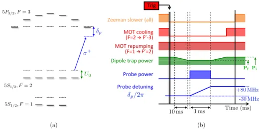
The operating parameters for the trapping laser are chosen to minimize the spontaneous emission rate while providing deep enough trapping potentials with reasonable laser power. Let us consider a 87Rb atom with transition frequencies !
1/2 (D1 line !!5S1/2 ↵
! !!5P1/2 ↵ at 795 nm) and !3/2 (D2 line 5S1/2 ! 5P3/2 at 780 nm). It is illuminated by a far-detuned
trapping laser of intensity I(~r) and frequency !L. We define the detunings δ1/2= !L− !1/2
and δ3/2= !L− !3/2. With the rotating wave approximation (RWA), the dipolar trapping
potential reads (Cohen-Tannoudji, Grynberg, and Dupont-Roc,1998;Grimm, Weidemüller, and Ovchinnikov,2000;Schlosser,2001):
1.1 Experimental requirements 11 800 820 840 860 880 900 920 940 0 20 40 60 80 100
Trapping laser wavelength l HnmL
Induced scattering rate Gsc max H s -1L 820 840 860 880 900 920 940 0 2 4 6 8 10
Trapping laser wavelength Λ HnmL
Laser power P HmW L Udip./kB' 1 mK ⇢ Udip./kB ' 1 mK NA = 0.5 (a) (b)
Figure 1.3: Choosing the wavelength of the trapping laser. (a) and (b) show respectively relevant orders of magnitude of the variation of the spontaneous emission rate induced by the dipole trap and the laser power needed for one dipole trap, as a function of the dipole trap wavelength (calculated using the rotating wave approximation).
Udip(~r) ' ~Γ2 8Isat I(~r) ∆eff , (1.3)
where Isat is the saturation intensity of the D1 and D2 transitions, and ∆eff is an effective
trapping laser detuning from the atomic resonances D1 and D2, defined by: 1 ∆eff = 1 3 δ1/2 + 2 3 δ3/2 . (1.4)
For red-detuned trapping laser (∆eff< 0), the potential is attractive towards the laser
in-tensity maxima. Efficient trapping is achieved when the potential depth is large com-pared to the kinetic energies of the atoms inside the MOT cloud characterized by a typical temperature TMOT' 100 µK. For a typical operating value of efficient trapping energy
|Udipmax|/kB' 1 mK, the ratio Imax/|∆eff| is thus fixed and can be estimated using Eq. 1.3
with the parameters of the D1 and D2 lines of87Rb (see Appendix A):
Imax
|∆eff|' 10
−5 W/(m2.rad.s−1). (1.5)
Finally, the trapping laser wavelength λ is chosen to minimize the scattering rate Γsc
re-sponsible for undesired decoherence in the two-level atomic system. In the limit of a low saturation of the atomic transition, Γsc can be written:
Γsc= I(~r) 8IsatΓ 3 1 3 δ2 1/2 + 2 3 δ2 3/2 ! . (1.6) Keeping Imax/|∆
eff| constant, Γmaxsc decreases as λ increases. At the same time, the
required trapping laser power P = ⇡w2
0I/2 for a Gaussian beam of peak intensity I = Imax
and waist w0' 1.22λ/NA increases with the trapping laser wavelength λ. The evolutions
of Γsc and P as a function of λ are shown in Fig. 1.3(a) and (b). On our experiment, it
was decided to operate with λ = 850 nm for which Γsc' 26 s−1 and Ptrap' 3.8 mW using
a focusing setup with NA = 0.5.
12 Chapter 1: New apparatus for single Rydberg atoms manipulation
Figure 1.4: Reaching the single atom regime. A fraction of the fluorescence light scattered by the trapped atoms is collected into a fiberized avalanche photodiode detector (APD) connected to a photon counting module. The number of counts per 10 milliseconds time bins is plotted as a function of time. At t = 0 ms, the atomic density in the MOT cloud is adjusted such that the loading rate R of the trap is bigger than the two-body loss rate. In this so called multi-atom regime, the trap can contain several atoms which scatter many photons. On the plot, the corresponding average detection rate on the APD detector is ⇠ 580 counts/(10 ms time bins). At t = 7500 ms, the current flowing in the MOT coils is ramped down; the atomic density in the MOT cloud and so the loading rate of the trap R start to decrease. Less and less atoms get trapped inside the tweezer, so the photons scattering rate detected onto the APD also decreases. By t ' 19000 ms, the signal can only take two main discrete values. This is the typical experimental signature that the single atom regime has been reached. We checked that the low fluorescence level corresponds only to background and dark counts detection. When the fluorescence signal is high, a single atom has been trapped in the tweezer.
atom regime and what were the corresponding constraints on the trapping laser parameters to reach it. The next step is to find a way to ’see’ when such a regime has been reached experimentally.
Imaging trapped single atoms
Inside the optical tweezer, trapped atoms continuously scatter many photons from the near-resonant cooling beams used for the magneto-optical trap (MOT). Those photons are col-lected on a photon counting detector to get an estimate of the trapped atoms number as a function of time. Then, starting with a high atomic density in the MOT cloud and reduc-ing it slowly, one can monitor the fluorescence signal collected from the dipole trap in real time. As the loading term R of the tweezer decreases, the average number of trapped atoms also decreases until it reaches the single atom regime. Such a procedure is represented in Fig. 1.4. The collection efficiency of the imaging system has to be large enough such that one can detect and count enough photons scattered by a single atom on a timescale small compared to the average time 1/R during which the single atom remains in the trap. A clever solution originally implemented inSchlosser, Reymond, and Grangier(2002) is to use the same optical system operating under vacuum to focus the ODT beam and to collect the fluorescence light emitted by the trapped atoms, as shown in Fig.1.2. A dichroic mirror is
1.1 Experimental requirements 13
Figure 1.5: Sketch of a two-atom experiment. A second ODT beam is combined with the first one with a small angle ✓ before entering the large NA objective of focal length f . In the focal plane, they create two distinct traps separated by the distance R ' f✓ as small as a few microns. Using a confocal imaging setup with a magnification > 25, it is then possible to use a mirror in the intermediate plane to separate the fluorescence scattered from of each trap and couple it into two distinct APD detectors.
used to separate the two wavelengths and the fluorescence can be coupled into a fiberized avalanche photodiode detector (APD). Single atom experiments can be triggered as soon as a rising edge of the fluorescence signal is detected.
From one to two-atom experiments
This trapping and imaging scheme can easily be scaled up for two-atom experiments. Two distinct ODT beams can be combined with a small angle ✓ before being sent through the imaging system of focal length f, and focused into the MOT cloud. At the focal plane, they create two distinct traps separated by a distance R ' f✓ of a few microns. It is then possible to separate the fluorescence signals emitted by two distinct single atoms in each trap by using a confocal imaging setup, as represented on 1.5. With a magnification of a few tens between the atoms plane and the intermediate plane, the distance between the two images is about one hundred microns. A mirror can be used to separate the fluorescence light scattered from each trap which can then be coupled to two distinct APD detectors. Thus, two-atom experiments can be triggered as soon as the two fluorescence signals are simultaneously above a given threshold.
14 Chapter 1: New apparatus for single Rydberg atoms manipulation
Figure 1.6: Sketch of the new compact setup for N -atom experiment. A spatial light modulator (SLM) inprints various 2D phase patterns on the incoming ODT beam. In the focal plane of the large NA objective, the light intensity profile is approximately the modulus square of the Fourier Transform (FT) of the initial incoming field. Almost arbitrary 2D intensity profiles can be engineered by calculating the right phase pattern to apply onto the ODT beam. Then, any 2D trapping geometry can be imaged onto an Electron Multiplying Charge Coupled Device (EMCCD) camera used in a confocal imaging setup for filtering unwanted background light.
Towards 2D patterns of single atoms
Increasing the number of traps by combining more and more beams quickly becomes expen-sive and cumbersome. Many research groups have investigated other ways to generate 2D arrays of dipole traps using arrays of microlenses (Dumke et al.,2002), optical lattices ( Nel-son, Li, and Weiss,2007), or diffractive optics (Piotrowicz et al.,2013) working with various interatomic distances, depth and volume of the traps.
Promising studies based on holographic techniques were conducted in our group during B. Darquié’s thesis around 2004 (Bergamini et al.,2004; Darquié,2005). A programmable spatial light modulator (SLM) was used to create arbitrary intensity patterns in the focal plane of the large NA imaging system, in which the single atom loading regime could be achieved. This device operates outside the vacuum chamber and allows to take advantage of the full numerical aperture of the trapping setup. Thanks to their rather low optical losses, standard SLM devices should allow us to produce up to fifty traps with an initial laser power of about 1 W. This scheme is currently under investigation but has already allowed us to produce up to 3 ⇥ 8 arrays of microscopic dipole traps as shown in Fig. 1.1. Once the 2D patterns of traps are created, one still needs to find a way to image the trapped atoms. It is very inconvenient to separate spatially the fluorescence light of more than two or three traps with confocal setups and mirrors. Instead, the SLM can be used in combination with an EMCCD camera. A sketch of the setup is represented in Fig. 1.6.
A major limitation to the scalability of the system is due to the stochastic process used so far for loading the traps. Deterministic loading schemes based on inelastic blue-detuned light-assisted collisions (Grünzweig et al.,2010) or taking advantage of the Rydberg blockade mechanism (Beterov et al.,2011) will be investigated. A first step in this last direction has been demonstrated recently inEbert et al. (2013).
1.1 Experimental requirements 15
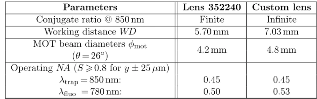
Figure 1.7: Molded aspheric lens from LightPathTechnologies! implemented by SortaisR et al. It is diffraction limited at both 850 nm and 780 nm up to NA = 0.5, and has a working distance of almost 6 mm which enables the crossing of small MOT cooling beams (see Fig.1.11for a clearer schematic).
Aspheric lenses for compact setup
The design of the large NA objective implemented on the pioneering experiment of (Schlosser, Reymond, and Grangier,2002) consisted of a vacuum compatible assembly of nine spherical lenses with stringent mechanical constraints on their alignment. Similar optical perfor-mances can now be reached with cheap off-the-shelf aspheric lenses. Previous experiments in our group (Sortais et al.,2007), and now in many other groups (Grünzweig et al.,2010) have implemented similar setups using a single aspheric lens to focus the trapping light and to image the trapped atoms. This achievement follows on recent advances in molding technology enabling the design of diffraction-limited and vacuum compatible aspheric lenses with large numerical aperture. These lenses are now available on the market for only a few hundreds of euros and can be found in a wide range of parameters such as focal, working dis-tance, or operating wavelength. Among them, some exhibit large enough working distances to allow for the crossing of small MOT cooling beams. Drawing and design specifications of the aspheric lens from LightPathTechnologies, implemented by Sortais et al. is shownR
in Fig.1.7. Conclusion
In order to create the 2D arrays of single atoms, the experimental requirements concerning the optical system are mainly twofold:
• First, a large numerical aperture (typically NA > 0.4) is needed to produce small traps with high two-body collision rates;
• Second, a large detection efficiency is required to detect the presence of the trapped atoms as quickly as possible.
A convenient compact solution is to use the same large NA molded aspheric lens to focus the ODT beams and to collect the fluorescence light emitted by the trapped single atoms. This provides large optical access for internal states manipulation of the trapped atoms. We will see below that the simplicity and the compactness of the setup is also crucial to implement the tools needed to control the electrostatic environment seen by the trapped atoms excited towards Rydberg states.
16 Chapter 1: New apparatus for single Rydberg atoms manipulation
1.1.2 Rydberg states manipulation
The second main challenge is to achieve the control of the dipole-dipole interactions between atoms excited to Rydberg states. These states exhibit large dipole moments which make them very sensitive to external electric fields.
Indeed, they are so sensitive that they can even be ionized in rather weak external electric fields. Taking advantage of this property, high-lying Rydberg states have been used as probes for compensating residual electric fields down to tens of microvolts per centimeter (Neukammer et al.,1987). They have also been used in spectroscopy setups as local sensitive electric field sensors to probe patch charges effect on conducting surfaces (Tauschinsky et al., 2010).
However, in our experiment, the atom-atom interactions strength depends strongly on the purity of the Rydberg states which could be contaminated by other unwanted states via Stark mixing. We will see how to avoid uncontrolled states mixing by implementing both a passive stable electrostatic environment and an accurate active experimental control of the static electric fields surrounding the atoms.
Avoiding patch charges effect from the lenses
On typical single atom trapping setups described in the previous section, the atoms electro-static environment can be affected by the proximity of dielectric surfaces exhibiting patch charges. Indeed, for a given large aperture angle needed for small trapping volume, the working distance between the trapped atoms and the closest dielectric surface of the imag-ing system depends only on the ’clear aperture’ diameter φcaof the last optical element (see
Fig. 1.11). Custom large diameter optics with large NA are hard to make so their price is prohibitively high; this was the main reason to use cheaper diffraction limited aspheric lenses with typical working distances on the order of 5 mm. Unfortunately, at such short distances, previous studies led by Alpha Gaetan and Charles Evellin (Gaetan,2009;Evellin, 2011) on the former Rydberg apparatus clearly showed the parasitic effect of patch charges accumulating on the last dielectric surface of a lens, only few millimeters away from the trapped atoms.
Indeed, patch charges are responsible for stray electric fields which induce energy shifts of the atomic Rydberg states via DC Stark effect. Those shifts can fluctuate over time while the charges rearrange slowly onto the dielectric surface. To be able to perform and read out a coherent optical transition between an initial ground state and a targeted Rydberg state, the induced Stark shift fluctuations have to remain much smaller than the laser excitation width during all the acquisition time of the coherent Rabi oscillations. On the former apparatus, the first experimental realizations of coherent transition between the ground state 5S1/2and the targeted Rydberg state 58D3/2exhibited a maximal Rabi frequency Ω = 2⇡⇥3 MHz. The
polarizability of the ground state can be neglected. The excited Rydberg state polarizability ↵ is on the order of 300 MHz/(V/cm)2 (see details in AppendixB). So we can estimate the static electric field F leading to a Stark effect ∆UStark shifting the atomic transition out of
resonance with respect to the excitation lasers:
Ω'∆U~Stark=1 2↵F 2 =) F 'r 2Ω↵ ' r 6 300' 150 mV/cm. (1.7)
The distance between the atom and the closest dielectric surface was 4 mm. By applying Coulomb’s law, an elementary charge q creates a field with amplitude Fq at distance r =
1.1 Experimental requirements 17
Figure 1.8: Influence of uncompensated residual DC fields on the Stark effect of the state 58D3/2. For a given fluctuation amplitude of stray fields δFfluct. along a chosen axis, the
stark shift fluctuation ∆E1(green) related to the zero-DC field case is much smaller than ∆E2(red)
where a permanent field Fperm.= 100 mV/cm is present.
4 mm:
Fq=
q
4⇡"0r2 ⇠ 10
−8V/cm. (1.8)
The number of elementary charges responsible for decreasing the contrast of coherent Rabi oscillations would then be about ∆Ncharges= F/Fq' 107. We will see in chapter 3
that we could observe the effect of such charges on the new apparatus, before correcting for it. The charges were most likely at the origin of drifting electric fields with amplitudes as high as 150 mV/cm. For Rydberg states with n > 50, such high stray fields can lead to neighboring states mixing which would completely prevent us from well controlling the atom-atom interactions.
One way to shield the atoms from these slowly drifting electric fields is to use a grid connected to the ground placed in front of the fields sources on the dielectric surface. Behind the grounded grid, the parasite field amplitude decreases exponentially with the distance towards the trapped atoms, with a decay length on the order of the grid spacing. However, it may affect the optical properties of the lens.
Another way is to use a conductive coating also connected to the ground on the lens itself. In our case, we used a transparent and colorless thin layer of indium tin oxide (ITO) coating1. The film is 200 nm thin and it has a transmission T
ITO>90 % for the operating
wavelengths 780 nm and 850 nm.
Active control of the electrostatic environment
Though stray fields fluctuations should be passively minimized as well as possible, it is also crucial to implement an active and accurate control of the electric environment surrounding the excited Rydberg atoms.
1
ITO is often used to make transparent conductive coatings for devices such as liquid crystal displays, flat panel displays, plasma displays, or touch panels.
18 Chapter 1: New apparatus for single Rydberg atoms manipulation
First, the Stark effect is quadratic for low angular moment states of Alkali atoms. So, the effect of residual charge fluctuations gets even worse if the 87Rb atoms are trapped in
a region where a permanent DC field Fperm. created by another steady source is already
present and cannot be compensated for, as shown in Fig. 1.8. By grounding most of the material surrounding the atoms, the amplitudes of these permanent fields are expected to be small but not negligible. Canceling them is a preliminary and necessary step towards the control of atomic interactions.
Second, the strength of the dipole-dipole interactions can be tuned up or down by using so called Förster resonances (see Sec.B.2). Those resonances occur in systems of two atoms A and B when two-Rydberg-atom states |Ψ1i = |r, ri and |Ψ2i = |r0r00i of energies E1 and
E2 are coupled by the dipole-dipole interaction. By applying an external electric field, these
states can get Stark shifted differently such that for a certain amplitude Fres. a perfect
degeneracy can be reached: E1= E2. This leads to an avoided level crossing for which the
strength of the dipole-dipole interaction is enhanced. For the resonances we can investigate in our experiment, the field amplitudes required to reach such a resonance are small, in the 10-100 mV/cm range. A well chosen set of at least four electrodes close to the atoms can be used to impose finely controlled electric fields in any given direction matching the resonance condition. These electrodes can be used to apply both compensation electric fields in the permanent regime, and add weak controlled pulsed fields to tune the system to a Förster resonance in a given time window.
Selective ionization and positive detection of Rydberg states
Finally, Rydberg states have low binding energies (⇠ 1 THz) so they can be ionized by rather weak static electric fields. A sensitive charge detector based on avalanche processes can then be used to detect the single ion or the single electron with detection efficiency up to 50 %. An estimate of the electric field Fioniz. required to ionize a given Rydberg state with an
effective principal quantum number n⇤
n,l,j can be obtained with a classical calculation (see
Sec. B.1.3), and reads:
Fioniz.= F0 16 n⇤ 4n,l,j, (1.9) with F0'16⇡✏0Ry 2 q3 ' 5 ⇥ 10 9V/cm, (1.10)
where Ry is the Rydberg unit of energy. For n > 40, the amplitudes of the fields required to ionize the Rydberg states do not exceed 150 V/cm. Furthermore, the precision required to discriminate between two nearby Rydberg states is reasonable. It is related to the typical spread in n⇤
n,l,j. Around n = 40−80 and for low orbital moment l = 0, 1, 2, the typical spread
∆n⇤n,l,j is 0.5 so the precision for the field amplitude can be estimated using Eq. 1.9:
∆Fioniz. Fioniz. = 4∆n ⇤ n,l,j n⇤ n,l,j ⇠ 4%. (1.11)
The voltage controlled power supply used to apply Fioniz. thus has to be accurate to
1.2 UHV compatible experimental apparatus design 19
Conclusion
To achieve a fine control over the dipole-dipole interactions between single Rydberg atoms, we have identified the following experimental requirements:
• First, the electrostatic environment of the trapped atoms has to be passively stable to avoid Rydberg states mixing. In our specific setup, patch charges at the surface of the lenses are the main source of fluctuating uncontrolled fields. These fields can be shielded by using a conductive ITO coating connected to ground;
• Second, an active control of static electric fields pointing in any chosen direction has to be implemented to compensate for stray DC stray fields, to manipulate Förster resonances and to apply pulses of ionizing fields. It is achievable by using controlled electrodes close to the atoms. Their design has to be vacuum compatible and take into account optical access needed for all the laser beams. A large dynamical range for the fields amplitude of about 10 mV/cm to 200 V/cm is required with a relative accuracy and repeatability 6 1 % both for fine tuning of Förster resonances (low fields), and for selective Rydberg states detection (high fields);
• Last, a sensitive charge detector combined with the pulses of ionizing fields can be used to implement a positive detection scheme of Rydberg states. This latter should not block the path of the laser beams and F -field lines must be carefully engineered so that single charged particles can be guided towards its detection area.
1.2
UHV compatible experimental apparatus design
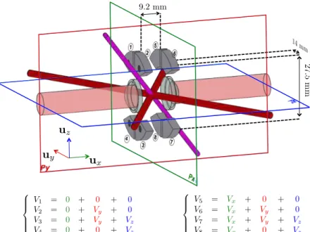
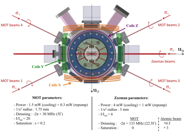
The crucial requirements needed for designing the new apparatus have been discussed in the previous section. We will now describe how the parts inside the science chamber were designed to reach the specifications. As we saw previously, the first step towards the study of interactions between single atoms is to create a cloud of cold rubidium 87 atoms. We have chosen to implement a standard MOT setup with three pairs of counterpropagating beams in a σ+−σ− configuration and a pair of anti-Helmholtz coils. Then the tools required for
Rydberg states manipulation of single atoms had to be incorporated. A sketch of a compact solution comprising the aspheric lenses, the electrodes, the MCP detector and the MOT coils is shown in Fig.1.9. To begin with, we designed the optical system consisting of the pair of identical aspheric lenses which sets the mechanical constraints for the other parts. 1.2.1 Custom aspheric lens
The specifications of the optical system are directly related to the atomic physics require-ments discussed in the previous section:
Optical specifications
High two-body losses rates, necessary to achieve the single atom regime, require the trapping volume to be as small as possible (see Eq1.1). Thus, the optical system has to be diffraction limited up to NA = 0.5 at the trapping wavelength λ = 850 nm. This can be quantitatively characterized by the Strehl ratio S = Ireal/Istig., where Ireal is the peak intensity of the
20 Chapter 1: New apparatus for single Rydberg atoms manipulation
Figure 1.9: Sketch of the setup inside the science chamber. An incoming atomic beam (green) is propagating in the y direction while it is being slowed down by a Zeeman slower laser beam to be loaded in a MOT. Two horizontal pairs (in the xy plane) and one vertical pair (along the z axis) of MOT beams (red) cross each other at the center of the reference frame. Two MOT coils (brown) used in anti-Helmholtz configuration are coaxial with the vertical axis z. A pair of two aspheric lenses (transparent blue) centered on the x axis are symmetrically positioned with respect to the MOT cloud. A collimated ODT beam (pink) propagating backward along the x axis is focused by the first aspheric lens on the right and gets collimated back after going through the second aspheric lens on the left. A set of four cloverleaf shaped electrodes (grey) encircles each aspheric lens. As we will see in more details in Sec. 1.2.3, it is a simple geometry to apply static electric fields in arbitrary directions. A micro-channel plate (MCP) detector (purple) stands below the incoming atomic beam. Its detection surface points towards the focal point of the ODT beam at the center of the diagram.
intensity of the same system without aberration (Born and Wolf, 2003). The Strehl ratio S is a quantity which lies between 0 and 1. It can be related to the quality of the real wavefront with respect to the stigmatic case. Let us define ∆ the wavefront deviation from the stigmatic reference over the aperture of the optical system, and σ2
∆= h(∆ − ∆)2i the
root mean square of the wavefront deviation. In the limit σ∆⌧ λ, one shows that: S ' exp✓ −4⇡ 2σ2 ∆ λ2 ◆ ' 1 −4⇡ 2σ2 ∆ λ2 . (1.12)
An arbitrary criterion commonly used in optics is to verify that S > 0.8 at the operating numerical aperture, which corresponds to σ∆= λ/14. A practical consequence is that the larger S, the deeper the optical trapping potential seen by the atoms will be for a given trapping laser power.
The same system is then used to collect fluorescence light emitted by the trapped atoms at λim.= 780 nm. For this wavelength, the collection efficiency has to be as large as possible.
In this configuration, the position of the object (the single atom) with respect to the optical system is determined by the focal point at 850 nm. The system can be affected by axial
1.2 UHV compatible experimental apparatus design 21
Emitting zone Collimated laser beam
100µm
Figure 1.10: Typical aspheric lens used for laser diode collimation. The radial profiles of aspheric lenses used for laser diode collimation are calculated to compensate for the residual spherical aberration due to 100 µm-slab of glass covering the emitting zone in standard diode packages.
chromatism such that the collected beam at 780 nm does not exit the vacuum chamber with the same divergence as the incoming trapping beam at 850 nm. This is not an issue as long as the angle is small enough such that a common imaging setup can be implemented. Finally, the long-term goal is to study N-single atom interactions trapped in 2D arrays of ODTs such as the patterns shown in Fig. 1.1up to about 9 by 9 traps with a typical separation of 5-6 µm. Thus, the system has to exhibit good optical performances off-axis up to fields of about ±(9-1)/2⇥6 µm = ±24 µm. Quantitatively, the Strehl ratio S has to remain bigger than 0.8 within a field of about ±24 µm for both the trapping and the imaging wavelength. Previous studies conducted in the group by Sortais et al. (2007) demonstrated that a single aspheric lens could achieve these specifications. However, at the time they built the first experiment, they directly bought the lens from LightPathTechnologies, catalogue.R
So the lens was not originally intended to be used for an atomic physics experiment and it had to be adapted to work as initially specified. When this project started in October 2010, LightPathTechnologies, assisted us for custom aspheric lens design. We took thisR
opportunity to try a new design, specifically adapted to our needs, and which could improve slightly the optical performances of the former lens.
Looking for improvements
We identified three points that could be improved by designing the lens profile ourselves: • First of all, a large proportion of large NA aspheric lenses produced in the industry
is used to collimate light emitted by laser diodes. These diodes are generally sold in standard packages where an active zone emits the laser light through a thin glass window as shown in Fig. 1.10. This slab of glass introduces spherical aberration as soon as the diode is working beyond the paraxial regime. The profile of the aspheric lens operating the collimation is then calculated to correct for this spherical aberration. In our case, when such a lens is used to focus a trapping laser beam under vacuum, there is no thin glass window anymore and a ’negative’ spherical aberration due to the lens shape itself appears. The way around used in Sortais et al. (2007) was to use the lens with finite conjugate ratio. It is possible to find an incident convergence angle for which the lens becomes aberration free. But then, one needs to control both the incoming beam diameter and the incident convergence angle on the lens, which further constrains the optical layout. By designing the aspheric profile ourselves, we could preserve the flexibility to work with a collimated incoming trapping beam. • The working distance WD between the last surface of the aspheric lens and the focal
interest-22 Chapter 1: New apparatus for single Rydberg atoms manipulation L φhold. θ x y α l1 l2 WD φca φmot
Figure 1.11: Geometry constraints on the MOT beam diameter. This sketch shows the two aspheric lenses facing each other in our experiment. The dashed parts correspond to the mechanical pieces needed to hold the lenses. Their thickness were reduced as much as possible with standard machining specifications down to 500 µm.
ing for two reasons. First, it also allows to increase the MOT beams diameter, which makes the alignment of the MOT setup a lot easier2. Second, once the MOT diameter
is fixed, increasing WD allows to avoid scattering light on the lens holders.
• Finally, the numerical aperture NA = sin ↵ of the imaging system at 780 nm (see Fig.1.11) could be larger, which increases the collection efficiency of the fluorescence emitted by the trapped atoms.
The two last points rely on the ability to mold diffraction limited aspheric lenses with large ’clear aperture’ diameter while keeping very good optical performances.
Design procedure with OSLO!R
Our contribution to the design of the custom aspheric lens was conducted with the soft-ware Optics Softsoft-ware for Layout and Optimization (OSLO,). This software implementsR
a method of sequential ray tracing between an object and an image plane through several interfaces based on Snell’s law of refraction. Each medium i is defined with an effective index ni, a thickness ti and the interfaces are cylindrically symmetric surfaces around the
propagation axis x described by a set of equations xi= fi(r), where xi is the surface
coordi-nate along the rotation axis, and r the distance to the x axis. Fig. 1.12(a) shows OSLO,R
environment for such interface specification. The goal was to define the equations of the two aspheric surfaces of the custom lens to minimize optical aberrations.
The general shape of the lens was the first parameter to decide on. In ray optics, for any conjugate ratio between an object and its image, there exists a certain lens shape that minimizes the 3rd order spherical aberration, which is the main aberration in our system
working almost only on-axis. In the case of infinite conjugate ratio and with a typical glass spherical singlet, the plano-convex shape with convex side towards the collimated incoming
2
The MOT beam diameter is constrained by the opto-mechanical geometry involving the diameter of the
mechanical lens holders φhold(almost equal to the clear aperture diameter φCA), the distance between the
holder and the focal point L, and the angle θ between an horizontal MOT beam and the atomic beam axis
y, as represented in Fig.1.11. They are related as follows:
2L = l1+ l2= φholdtan θ +
φmot
1.2 UHV compatible experimental apparatus design 23
(a) (b)
Figure 1.12: OSLO! environment. (a) shows the design environment interface. (b) representsR
a set of 40 incoming rays parallel to the optical axis passing through the optical system in 2D. The system is not yet optimized, and the operating numerical aperture is large, on the order of 0.5, so the spherical aberration is colossal. The caustic curve of the spherical aberration can even be observed at this scale. In the paraxial focal plane, the resulting geometrical spot diameter is about 2 mm.
trapping beam performs nearly as well as the best-form spherical lens. It is a quite popular shape, because a plano-convex lens costs much less to manufacture than an asymmetric biconvex singlet.
Once the general shape was chosen, we chose the clear aperture diameter φca to be as
large as possible. With tooling diameter limited to 20 mm used for the molding process, lenses with maximum outer diameter up to 15 mm could be achieved. Then, a 1 mm thick flat bored flange required to tighten the molds together during the process limits the maximum effective outer diameter down from 15 mm to 13 mm. Last, a blending radius due to releasing of molds during fabrication eventually fixes the upper bound for the clear aperture diameter φca= 12.5 mm up to which theoretical aspheric profiles with diffraction limited performances
could be guaranteed.
Then, for an infinite conjugate ratio configuration with a numerical aperture NA > 0.5 at 850 nm, the effective focal length is upper bounded as: fefl6 φca/(2↵) ' 10.8 mm. We fixed
this value to 10 mm to keep a large enough working distance WD. Assuming the central thickness CT of the lens to be small enough such that thin lens approximation is valid, the curvature radii of the lens could be estimated using the lens-maker’s formula:
1 f = (n850− 1) ✓ 1 R1 − 1 R2 ◆ , (1.14)
where f is the focal length, n850 is the refractive index of the lens material at 850 nm,
and R1,2 are the algebric radii of curvature of the two lens surfaces measured from the front
surfaces towards their centers of curvature. The chosen plano-convex shape implies R2= 1.
The glass used for molding is D-ZLAF52LA with a refraction index n850= 1.7902 so we
could estimate R1= 7.9 mm. With a reasonable value of the central thickness CT ' 5.4 mm,
OSLO, could be used to check the expected behaviour of the initial system. At this point,R
the spherical aberration of the system was colossal, and led to a geometrical spot with a radius on the order of 900 µm as shown in Fig.1.12(b).
The following step was to make the surface aspheric. Rotationally symmetric aspheric surfaces passing through the origin are commonly described by the equation:
x = r 2 R (1 + q 1 − (1 + )Rr22) + A4r4+ A6r6+ A8r8+ A10r10+ A12r12+ ... , (1.15)