FPGA based hardware acceleration of a BRIEF correlator
module for a monocular SLAM application
François BRENOT, Jonathan PIAT
LAAS-CNRS, University of Toulouse, CNRS 7 Avenue du Colonel Roche
Toulouse, France
fbrenot@laas.fr
jpiat@laas.fr
Philippe FILLATREAU
Laboratoire Genie de Production, INP-ENIT, University of Toulouse
47 Avenue d’Azereix Tarbes, France
philippe.fillatreau@enit.fr
ABSTRACT
Robot localization is a mandatory ability for the robot to navigate the world. Solving the SLAM (Simultaneous Lo-calization and Mapping) allows the robot to both localize itself in the environment while building a map of its sur-rounding. Vision-based SLAM uses one or more camera as the main source of information. The SLAM involves a large computation load on its own and using vision involves even more complexity that does not scale well. This increasing complexity makes it hard to solve in real-time for applica-tions where the SLAM high rate and low latency are inherent constraints (Advanced Drivers Assistance Systems). To help robots solve the SLAM in real-time we propose to build a vision-core that aims at processing the pixel stream com-ing from the camera in a vision front-end that let a SLAM method work only with high-level features extracted from the image. This paper describes the implementation on FPGA of a core that computes the BRIEF descriptor from a camera output. We also present the implementation of the correlation method for this descriptor for the tracking in an image sequence. This core is then tested in an embedded SLAM application with good speed-up.
Keywords
FPGA, SLAM, Features, Embedded system, Robotics
1.
INTRODUCTION
One of the important aspects of robot navigation is the ability to locate the robot and build a map of its surround-ings. SLAM (Simultaneous Localization And Mapping) al-gorithms target such a goal by fusioning multiple sensor inputs (depth scanner, inertial measurement unit, gps, vi-sion. . . ) to estimate the state of the robot in its environment and to incrementally build a map of its surrounding.
Vision based SLAM uses one or more camera to extract and track information from the scene (features) which al-lows to estimate the robot position and incrementally build
the environment map. The SLAM problem can be solved using a number of different methods, including Kalman Fil-ter (KF) and Bundle Adjustement (BA). Most methods rely on the same vision processing tasks : feature detection and tracking. These two tasks represent an important part of the processing time of the SLAM and leveraging the power of hardware accelerators to solve them can yield great process-ing time and power consumption improvements. Moreover computer-vision performed in software does not scale-well in term of resolution and number of sensors where hardware accelerator can help linearize computing cost.
The BRIEF (Binary Robust Independent Element Fea-ture) feature descriptor is a simple yet efficient method to extract an image feature signature. This signature can then be correlated with an image region to track it in an image sequence. This descriptor simplicity makes it a good candi-date for hardware implementation. Combined with a FAST feature detector it allows a compact hardware implementa-tion able to detect and track multiple features from a pixel stream. Stream processing of pixel coming out of a camera permits to eliminate image buffering and provides detection and tracking results with almost zero latency (a few image lines of latency). The implementation of the BRIEF de-scriptor and correlator in hardware permits to target a fully functional embedded SLAM system with all vision operators migrated to hardware.
This paper focuses on the design of a hardware accelera-tor for BRIEF feature tracking. This core is integrated in a Extended Kalman Filter SLAM framework to reach real-time performances (image acquired at 30Hz) on an embed-ded platform (ZedBoard, ZynQ 7020). In a first part we introduce the SLAM context and the associated computer vision operators. In a second part we introduce the design of the correlation core, then its integration in the architecture. We finally conclude with results and perspectives.
2.
VISION-BASED SLAM
2.1
The generic SLAM problem
The problem known in the literature as SLAM (Simul-taneous Localization And Mapping) consists in estimating jointly the robot pose and the positions of a set of static landmarks in the environment.
Figure 1, shows the different steps in the SLAM process: (A) The robot observes by first time the three landmarks (the corners of the squares); (B) the robot moves, it knows its position with uncertainty; (C) the robot re-observes the
an author's http://oatao.univ-toulouse.fr/20222
https://dl.acm.org/citation.cfm?doid=2967413.2967426
BBrenot, François and Piat, Jonathan and Fillatreau, Philippe FPGA based hardware acceleration of a BRIEF correlator module for a monocular SLAM application. (2016) In: 10th International Conference on Distributed Smart Camera (ICDSC 2016), 12 September 2016 - 15 September 2016 (Paris, France).
landmarks; (D) merging this observation(s) with the map constructed previously reduces both robot and landmarks position uncertainty.
Figure 1: Steps in the SLAM algorithm
Figure 2 shows a general view of a generic SLAM archi-tecture.
Figure 2: Generic architecture to solve the SLAM problem
2.2
Vision operators for the SLAM
In a vision-based SLAM implementation the robot uses exteroceptive informations extracted from a scene perceived through one [4] [9] or more cameras [12]. Most SLAM im-plementations use sparse informations extracted from the image refered to as features. Constraints for a feature to be used for localization are its ability to be tracked over time in the image sequence, and to be static in the reference frame used for localization (world frame). One widely use image feature is texture corner since it is easy to detect and is stable over time.
2.2.1
Feature detection
There exist a wide variety of coner detectors for images. The Harris detector is based on the gray level partial spatial derivatives [6] around the pixel of interest.
The FAST [10] corner detector simplifies the process by analyzing the local gradient only between a central pixel and the pixels on Bresenham circle pattern. FAST detector complexity is very low and only requires integers operations when Harris (and others) require more complex arithmetic. This simplicity and good stability makes it a good candi-date for hardware implementation. Other corner detection methods are proposed for corners such as SIFT [7] (Scale Invariant Feature Transform) or SURF (Speed-Up Robust Feature) [1]. These methods relies on DoG (Difference of Gaussian) for corner detection and shows very good perfor-mance and invariance to change of scale and rotation. How-ever those methods prove to be computationally complex and resource consuming (for an hardware implementation).
2.2.2
Feature correlation
Once detected the feature is initialized in the SLAM as a landmark. Tracking the feature over time can be performed in two different ways. Tracking by detection uses the de-tected corners to be associated with the features stored in the map .This tracking technique requires a stable corner de-tector (same corner will be detected in an image sequence). Features can also be tracked using active search. In this technique the SLAM algorithm computes a search window for the features of the map where the correlation is per-formed. This method is more reliable to succesfully track the features but can be computationnaly complex depend-ing on the search window size.
Correlation methods for a feature can be divided in two classes : template-based and descriptor-based. Template-based directly correlates two image regions : it correlates the neighborhood of the feature in the search window. Different method exists to compute the correlation score that each tries to improve stability (SAD, SSD, CC, ZCC, ZNCC) with increasing arithmetic complexity.
Descriptor-based correlator, computes a signature (tor) for the feature, based on its neigborhood. This descrip-tor is then compared with the descripdescrip-tor extracted for a posi-tion in the image. Methods such as SIFT [7] computes a 128 element descriptor which is based on gradient orientation in the neighborhood of the point of interest. SURF [1]features uses a 64 to 128 element vector extracted by computing the HAAR wavelet response in a 20 × 20 neighborhood centered on the pixel of interest.
BRIEF (Binary Robuste Independent Element Feature) [3] is a binary feature descriptor that describes the distri-bution of gradients in the neighborhood of the pixel of in-terest. First a N × N patch center on the pixel of interest is extracted. M pairs of pixels in the patch are randomly selected and for each pair p0, p1 a bit is generated with the
following rule :
bm=
(
1 if p0< p1
0
Figure 3: Image feature and corresponding 8-bit BRIEF descriptor. Vectors picture the pixel pairs elected for comparison.
This results in a M -bits long binary descriptor. Com-paring two descriptor is simply done using the Hamming distance. This descriptor can be computed very fast, is very compact and exhibit good stability for the matching. The descriptor is robust to illumination changes and small rota-tions (less than 15◦) [3] which makes it a good candidates
for hardware implementation.
In the following work we will use texture corners detected in the image as features. We chose to use the FAST al-gorithm to detect the features that are then described and tracked using a active-search of the BRIEF descriptor.
2.2.3
Hardware architectures for vision-based SLAM
There exist several contributions for a embedded SLAM architecture. In [8] the authors only implements the cor-ner detection and sensors synchronisation (for an IMU) in hardware while other image processing tasks and SLAM are computed in software. The SLAM is performed using an optimisation method and runs on a separate computer.In [2] the authors implements the SIFT feature descriptor in hardware to be used for a EKF-SLAM application using 4 QVGA cameras on a FPGA platform. This implementation runs the correlation part in sowftare on an embedded soft-core to produce a 2D map of the environment.
3.
BRIEF CORRELATION CORE
The BRIEF descriptor exhibits nice properties for its im-plementation in hardware. The computation of the descrip-tor requires only differences between 8-bit pixel values and the Hamming distance can be computed easily with an adder tree.
For our system we target a core that can directly process the pixel stream from a camera while storing the minimum amount of data (no full-frame buffering, pixel stream pro-cessing). This core will be clocked directly by the pixel clock of the camera that is independent of the system clock (but lower). In the following we will describe the implementation details that allows to meet those requirements.
3.1
BRIEF descriptor extraction
Experimentation in software showed that a 9×9 patch size and a 128-bit length of the BRIEF descriptor are enough to ensure stability of the tracking while minimizing the resource usage. Since our processing system is based on a streaming architecture, the computation of the descriptor requires to buffer a 9×9 sliding window from the incoming pixel stream. This memory cache uses enough BRAM memory to store 8 lines of the image and registers to store 8 pixels of the last line of the patch (Figure 4).
Figure 4: Behavior of the 9x9 sliding window. Pink indicate content retrieved from BRAM, Blue indi-cate content of registers and Green indiindi-cate incom-ing pixel from the camera
This 9×9 window is used for the BRIEF computation with a statically generated pattern of 128 pixel pairs comparison (Figure 5). This comparison pattern being generated stat-ically the synthesizer can perform a deeper optimization of
the comparison logic. The descriptor is computed at the pixel rate and can be latched whenever a corner is detected. Its worth noting that the same 9 × 9 pixel window can be used for the corner detection (FAST uses a 7 × 7 window to detect a corner).
Figure 5: Architecture for the extraction of a 128bit BRIEF descritpor from a pixel stream
3.2
Hamming distance computation
Hamming distance is defined as the number of bits that differs in a pair of N -bit words. The computation requires to first perform a bit-wise XOR of the two words and then count the ones in the resulting word (population count). The XOR operation is combinational but the computation of the Hamming distance requires more work to be performed in a frequency and resource efficient manner.
Counting the ones in a word can be performed in different ways:
1. Sequential count of the ones : scanning the word and incrementing a counter every time a one is detected. 2. Parallel count of the ones : Computing partial
Ham-ming distance in parallel and iteratively add them. A sequential count of the ones is done using an adder cas-cade. In this technique counting a N -bit word requires N/2 chained counter. This counting technique gives very poor frequency performance since the max combinational path goes through N adders (Figure 6). Frequency performance can be improved by pipelining every stage of cascade.
Figure 6: Adder cascade for polulation count on a 4-bit word
The computation of the Hamming distance for a word of length 128 bits, using a sequential count will require 64 stages.
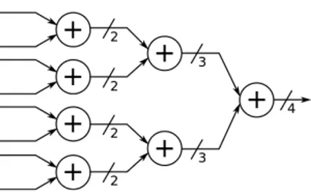
Parallel count of the ones can be performed using an adder-tree. The adder tree will have ceil(log2(N )) stages
each composed of N/(stageindex+1) adders of 2(stageindex+1)
width (Figure 7). The adder tree can be fully combinational with a large impact on the maximum system frequency or pipelined at the cost of resources but better frequency per-formance.
For the computation of the Hamming distance for a word of length 128 bits, the resulting adder tree will thus be 7
Figure 7: Adder tree for population count on a 8-bit word
stages deep. While the number of adder in each stage mainly has an impact on resource count, the depth of the adder tree will impact the maximum frequency of the core (hence reducing maximum pixel clock our system can handle) since it directly conditions the maximum combinational path.
To target a system driven by the pixel clock (distance must be computed at each clock cycle) with maximum fre-quency performance and minimal resource count, we will only investigate the parallel approach. In this work we ex-plore different solutions to the parallel bit-counting prob-lem. To find a better trade-off between system frequency and resource usage than the aforementioned methods.We will specifically explore solutions taking advantage of FPGA specific resources : LUT and Block RAMs.
3.2.1
LUT-based Hamming distance computation
Naive implementation of the adder-tree uses 1-bit adders at the first stage of the tree. This means that this first stage needs N/2 1-bit adders. In [11] the authors propose to implement the Hamming distance using LUT. Adding 2-bits can be seen as a combinational function with the following thruth table : b1 b0 r1 r0 0 0 0 0 0 1 0 1 1 0 0 1 1 1 1 0A truth table can be mapped to MUX and LUTs in the FPGA fabric. FPGA generic slices contains one or more LUT with varying input size depending on the vendor and model of the FPGA. In Xilinx portfolio, modern FPGAs (from Spartan-6 on) use 6 inputs LUT with one output. This means that instead of using 1-bit adders in the first stage of the adder tree we can map the add function to the inputs of three 6-input LUTs effectively computing the Hamming distance for a 6-bits word. For a word of size N -bits, we thus consume (N/6) ∗ 3 LUT in the first stage of the tree and then ceil(log2(N/6)) stage of adders to compute the
Hamming distance (Figure 8). The resulting reduction in the adder tree depth has a direct impact on the maximum frequency of the haming distance core, and efficiently maps to FPGA resources.
For the computation of the Hamming distance on our 128-bit word we thus need a adder-tree of depth 5 with a first stage composed of (3*22) 6-inputs LUT.
3.2.2
BRAM-based Hamming distance computation
Figure 8: Adder tree for the population count on a 8-bit word using LUT. LUT are limited to 4-inputs in this figure
Aforementioned method mapped the first stage of the adder tree to 6-inputs LUTS to limit adder tree depth and increase maximum system frequency. Dual-port BRAM is another resource usually available in modern FPGAs. These BRAMs allows for dual simultaneous read access using two independent ports. A BRAMs being a memory, it can also be seen as a large LUT with inputs being the address and content being the LUT output. A BRAM with a Addresswidth
and Datawidthcan be used as an Addresswidthinputs LUT
with Datawidthoutput. Using a BRAM to hold a Addresswidth
bit-counting LUT will require Datawidth= ceil(Addresswidth/2).
For example a BRAM with a address bus size of 8 will need to hold 4-bit data. This means that we can replace the first stage of our adder-tree with BRAMs (one BRAM can be used for two addition thanks to the dual port) and consume (N/8)/2 BRAM for the first stage and then ceil(log2((N/8)/2))
adder stage to compute the Hamming distance (Figure 9).
Figure 9: Adder tree for population count on a 16-bit word using Dual Port Block Ram. Each port of the RAM is used as an independent counter
For the computation of the Hamming distance on our 128-bit word we would need a adder tree or depth 3 with a first stage composed of 8 dual port BRAMs with 8-bit address bus and 4-bit data bus.
All these methods are good solutions to the population count problem. The LUT implementation gives the best performance/resource ratio but depending on the resources available for a given architecture the designer could choose to use the BRAM-based method.
3.3
Correlation Core architecture
In our SLAM implementation the observation of land-marks is performed by the active-search of feature
descrip-tors in the image sequence. This SLAM implementation uses a short-term map containing a maximum of 20 landmarks, with only up to 6 landmarks observation being used for cor-rection at each iteration. Our accelerator allows to track 20 features in the image sequence, thus allowing to observe every landmark of the map. The core is loaded with BRIEF descriptors and corresponding search window position and area. It is then driven by the pixel clock and update the current position in the image. This position and current pixel BRIEF descriptor are passed to 20 Hamming distance computation cores that are only active when current posi-tion is within their correlaposi-tion window (Figure 10). Each of the Hamming distance is used to drive memory signals with minimum Hamming distance found and its position in the search window.
Figure 10: Correlation-core for one correlator
4.
RESULTS
4.1
Synthesis of the correlation core
The correlation core was synthesized for a ZynQ 7020 to evaluate resource usage and maximum frequency. For a sin-gle correlator, the adder-tree methods gives a fair resource usage and shows a max frequency of 150.921MHz. The LUT-based bit-counter shows the best frequency for the mini-mum resource usage with a max frequency of 160.436MHz while showing a 20% reduction in resources usage (only on LUTs). The BRAM approach has good frequency perfor-mance (140MHz) and use 50% less LUT but would uses too many of the available BRAMs of the target platform. More-over Xiling 7 series logic uses 18kbit to 36kbit block ram with data witdh of 1, 2, 4, 9, 18. When using these block RAM with 8-bit address width and 4-bit data width we largely sub-utilize each block RAM.
When increasing the number of correlators to 20, the fre-quency is not impacted by the place and route thanks to the low resource usage. The LUT based method can still go higher in pixel clock frequency and still consumes 20% less resources than the adder-tree. To minimize the resource us-age of the overal application we chose to use the LUT-based method in our architecture. The synthesis report for the 20 LUT-based correlators is shown in 1.
4.2
Integration in the embedded SLAM
archi-tecture
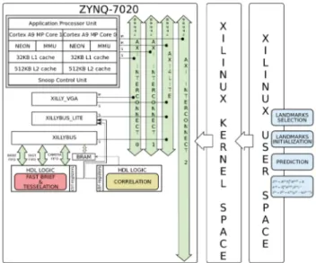
Our accelerator was integrated on the ZedBoard platform using the Xillybus framework. This framework consists in a Linux distribution for the dual-core ARM with simple to use drivers for memory mapped accelerators and FIFO commu-nication with hardware cores (Figure 11). This distribution
Type Available Used Ratio
Slice Registers 106400 6850 6%
Slice LUTs 53200 9864 18%
LUT Flip Flop pairs : 12511 -With an unused Flip Flop 5661 45%
-With an unused LUT 2647 21%
-Fully used LUT-FF pairs 4203 33% Table 1: Synthesis report for the LUT-based corre-lator for 20 features
was chosen to ease the debugging but will later be replaced with custom drivers for the core. The architecture also inte-grates a FAST corner detector and interfaces the correlation core using memory mapped BRAMs. To mimic a camera connected to the logic, we use a hardware block that sim-ulates camera signals from pixels received through Xillybus FIFOs. The Xillybus architecture limits the system clock to 80Mhz for the logic side which limits the performance of the correlator module.
Figure 11: Correlation core integrated in our vision-based SLAM system
The correlation core was first tested using artifical images to assess and debug the core behavior. The core was then integrated in the software architecture for our vision-based EKF-SLAM implementation in place of the existing software code. Functions calls for the correlation of a given feature were replaced with calls to the hardware accelerators using Xillybus peripheral drivers.
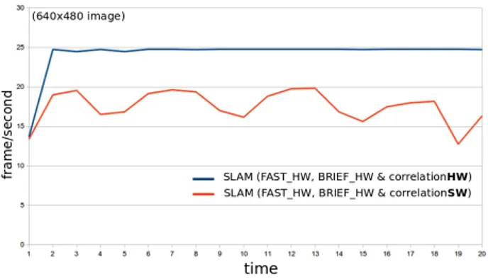
On this architecture the performance of the EK-SLAM with FAST corners extracted in hardware was limited to an average of 18Hz but adding the BRIEF correlation core allowed to increase this frequency to 24Hz. Moerover the BRIEF correlator allowed to stabilize the frame-rate, when correlation performed in software would make the frame-rate varry a lot depending on the search window area (Figure 12). This 24Hz figure is still far from our 30Hz goal but its worth noting that profiling showed that reading image from disk represents 24% of the computation time and Xilly-bus communications would create a significant slow-down.
Figure 12: EKF-SLAM rate plotting with and with-out correlation-core
Moreover since, the camera is simulated, images needs to be transferred from system memory to logic with a great impact on maximum rate of our SLAM implementation.
In [2] and [13] the authors implements the SIFT feature descriptor in hardware. The SIFT feature descriptor is bet-ter than BRIEF in bet-terms of stability, but the resource count is much higher with the use of DSP blocks (respectively 64 and 97), more LUT (respectively 35k and 43k), more regis-ters ( 19k for both) and run at much lower frame-rate (30 FPS for QVGA images in [2] and 30 FPS for VGA images in [13]). Moreover these two design only compute the descrip-tor, while the correlation is performed in software. In [5] the authors use a FPGA to compute a 256-bit BRIEF de-scriptor. The implementation only consider the descriptor computation and was designed using HLS tools. This imple-mentation is shown to work well for QVGA images stored in memory and processed using a 125MHz system clock but no implementation of the correlator is proposed.
5.
CONCLUSION AND FUTURE WORK
In this paper we presented a novel architecture for BRIEF descriptor computation and correlation tested in a 3D EKF-SLAM application. This hardware accelerator proves to be valuable to reach higher frame-rate in an embedded SLAM. The correlation core can process up to 160MHz pixel stream which correspond to VGA resolution at 390 frames per sec-ond (or higher resolution at lower frame-rate).
While the core was tested in a EKF-SLAM software im-plementation, there is no reason why it would be limited to EKF-SLAM. OTher applicaiton using feature detection and tracking could also benefit from the same level of speed-up. The core could be further enhanced with a correlation scheduler that would allow to match more than 20 features. The current design works for a worst case where the search window for each feature is as large as the image itself. In a real world scenario, this case should never occur and most of the correlation cores will be inactive most of the time. By using a correlator scheduler, one could use the core to track more than 20 features, one correlator being used to track multiple features with non-overlapping search windows.
The next step for our embedded EKF-SLAM implemen-tation is to integrate a custom designed camera module (60FPS global shutter) to perform real-time image stream-processing and low-latency SLAM.
6.
REFERENCES
[1] Herbert Bay, Andreas Ess, Tinne Tuytelaars, and Luc Van Gool. Speeded-up robust features (surf). Comput. Vis. Image Underst., 110(3):346–359, June 2008. [2] V. Bonato, E. Marques, and G. A. Constantinides. A
parallel hardware architecture for scale and rotation invariant feature detection. IEEE Transactions on Circuits and Systems for Video Technology, 18(12):1703–1712, Dec 2008.
[3] M. Calonder, V. Lepetit, M. Ozuysal, T. Trzcinski, C. Strecha, and P. Fua. BRIEF: Computing a Local Binary Descriptor Very Fast. IEEE Transactions on Pattern Analysis and Machine Intelligence,
34(7):1281–1298, 2012.
[4] A.J. Davison, I.D. Reid, N.D. Molton, and O. Stasse. Monoslam: Real-time single camera slam. IEEE Trans. Pattern Anal. Mach. Intell., 29:1052–1067, June 2007.
[5] R. de Lima, J. Martinez-Carranza, A. Morales-Reyes, and R. Cumplido. Accelerating the construction of brief descriptors using an fpga-based architecture. In 2015 International Conference on ReConFigurable Computing and FPGAs (ReConFig), pages 1–6, Dec 2015.
[6] C. Harris and M. Stephens. A combined corner and edge detector. In Proceedings of the 4th Alvey Vision Conference, pages 147–151, 1988.
[7] D. G. Lowe. Object recognition from local
scale-invariant features. In Computer Vision, 1999. The Proceedings of the Seventh IEEE International Conference on, volume 2, pages 1150–1157 vol.2, 1999. [8] J. Nikolic, J. Rehder, M. Burri, P. Gohl,
S. Leutenegger, P. T. Furgale, and R. Siegwart. A synchronized visual-inertial sensor system with fpga pre-processing for accurate real-time slam. In 2014 IEEE International Conference on Robotics and Automation (ICRA), pages 431–437, May 2014. [9] J. Piat, D. A. M ˜Aarquez-G ˜֒ Aamez, and M. Devy.֒
Embedded vision-based slam: A model-driven approach. In Design and Architectures for Signal and Image Processing (DASIP), 2013 Conference on, pages 284–289, Oct 2013.
[10] Edward Rosten and Tom Drummond. Fusing points and lines for high performance tracking. In IEEE International Conference on Computer Vision, volume 2, pages 1508–1511, October 2005.
[11] V. Sklyarov, I. Skliarova, A. Sudnitson, and M. Kruus. FPGA-based time and cost effective Hamming weight comparators for binary vectors. In IEEE EUROCON 2015 - International Conference on Computer as a Tool (EUROCON), pages 1–6, September 2015. [12] J. Sola, A. Monin, and M. Devy. Bicamslam: Two
times mono is more than stereo. In Proceedings 2007 IEEE International Conference on Robotics and Automation, pages 4795–4800, April 2007. [13] L. Yao, H. Feng, Y. Zhu, Z. Jiang, D. Zhao, and
W. Feng. An architecture of optimised sift feature detection for an fpga implementation of an image matcher. In Field-Programmable Technology, 2009. FPT 2009. International Conference on, pages 30–37, Dec 2009.