En vue de l'obtention du
DOCTORAT DE L'UNIVERSITÉ DE TOULOUSE
Délivré par :
Institut National Polytechnique de Toulouse (INP Toulouse)
Discipline ou spécialité :
Réseaux, Télécommunications, Systèmes et Architecture
Présentée et soutenue par :
M. HAMDI AYED
le jeudi 27 novembre 2014
Titre :
Unité de recherche :
Ecole doctorale :
ANALYSE ET OPTIMISATION DES RESEAUX AVIONIQUES
HETEROGENES
Mathématiques, Informatique, Télécommunications de Toulouse (MITT)
Institut de Recherche en Informatique de Toulouse (I.R.I.T.)
Directeur(s) de Thèse :
M. CHRISTIAN FRABOUL M. AHLEM MIFDAOUI
Rapporteurs :
M. LAURENT GEORGE, UNIVERSITE DE MARNE LA VALLEE M. YE-QIONG SONG, UNIVERSITE DE LORRAINE
Membre(s) du jury :
1 M. LAURENT GEORGE, UNIVERSITE DE MARNE LA VALLEE, Président
2 M. AHLEM MIFDAOUI, ISAE TOULOUSE, Membre
2 M. CHRISTIAN FRABOUL, INP TOULOUSE, Membre
2 M. JUAN LOPEZ, AIRBUS FRANCE, Membre
Acknowledgments
I would like to express my sincere gratitude to my supervisor Christian Fraboul and Co-supervisor Ahlem Mifdaoui for their constant support, guidance and patience during my research. I thank them for their precious advice, availability and kindness they have shown during my thesis. Without their help and support in the difficult moments this thesis would not have been possible.
I am thankful for Ye-Qiong Song and Laurent George for accepting to be my thesis referees. I am also very honored to count them among the members of the jury of my thesis as well as Luis Almeida and Juan Lopez.
I would like to thank Sylvie Eichen for her precious help in administrative tasks. I thank all the people that i worked or interacted with at the Department of Computer Science, Mathematics and Automatics (DMIA) of the ISAE (Jolimont site). In particular, I am grateful to Emmanuel Lochin, Fabrice Frances, Jerome Lacan, Patrick Senac, Tan-guy Perennou and Pierre de-Saqui-Sannes for the many useful discussions and precious advice. I thank Thomas, Remi, Hugo, Anh-Dung, Nicolas, Victor, L´eo, Jonathan, Tuan, Khanh, Viet, Rami, Karine, Ahmed and everyone in the DMIA department for providing me a friendly working environment.
Abstract
The complexity of avionic communication architecture is increasing due to the grow-ing number of interconnected end-systems and the expansion of exchanged data. To be effective in meeting the emerging requirements in terms of bandwidth, latency and modularity, the current avionic communication architecture consists of an Avionics Full DupleX Switched Ethernet (AFDX) network to interconnect the critical end-systems and some Input/ Output (I/O) data buses (e.g., Controller Area Network (CAN) bus) for sen-sors and actuators. Clusters are then interconnected via specific devices, called Remote Data Concentrators (RDCs), standardized as ARINC 655. RDC devices are modular gateways distributed throughout the aircraft to handle heterogeneity between the AFDX backbone and I/O data buses. Although RDC devices enhance avionics modularity and reduce maintenance efforts, they become one of the major challenges in the design pro-cess of such multi-cluster avionic architectures. The existing implementations of RDC are usually based on direct frames translation and do not consider resource savings issue. Resource utilization efficiency is important for avionic applications to guarantee easy in-cremental design, and enhance margins for future avionic functions additions. Therefore, the design of an optimized RDC device integrating resource saving mechanisms becomes a necessity to enhance the scalability and performances of avionic applications. In this context, the main objective of this thesis is to design and validate an enhanced RDC device offering an efficient bandwidth utilization, considered as a main resource to save, while meeting real-time constraints.
To achieve this aim, first, we design an enhanced CAN-AFDX RDC device compliant with the ARINC 655 specifications. The main elementary functions integrated into the proposed RDC are: (i) frame packing applied on upstream flows, i.e., flows generated by sensors and destined to the AFDX, to minimize communication overheads, and con-sequently bandwidth utilization; (ii) hierarchical traffic shaping applied on downstream flows, i.e., flows generated by AFDX sources and destined to actuators, to reduce inter-ferences on CAN, and thus to enhance communication efficiency. Moreover, our proposed RDC may connect multiple I/O CAN buses using a partitioning process to guarantee the isolation between different criticality levels.
Second, to analyze the effects of our proposed RDC on the system’s performance, we detail the modeling of the CAN-AFDX architecture, and especially the RDC device and its implemented functions. Afterwards, we conduct timing analysis to compute end-to-end delay bounds and to verify real-time constraints. Preliminary performance analysis of our proposed RDC device through simple examples shows the efficiency of frame packing and traffic shaping processes to enhance resource savings in terms of AFDX bandwidth utilization.
Many RDC configurations can meet the system requirements while enhancing resource savings. Hence, we proceed to tuning of our RDC parameters to maximize as much as possible resource savings, and consequently to minimize the AFDX bandwidth utilization while meeting the system constraints. However, this RDC tuning problem turned to be a NP-hard problem, and adequate heuristic methods are introduced to find the accurate RDC parameters. Preliminary performance evaluation of our optimized RDC device has been performed, and obtained results show significant enhancements in terms of band-width utilization reduction, with reference to the currently used RDC device.
Finally, the performances of the proposed RDC device are validated through a real-istic CAN-AFDX avionics architecture. Different I/O CAN loads have been considered to check the scalability of the integrated RDC functions, i.e., frame packing and traffic shaping. The obtained results confirm our first conclusions and highlight the ability of our proposed RDC device to maximize resource savings, while meeting the real-time con-straints. For instance, the optimized RDC device offers a bandwidth utilization reduction of more than 40% compared to current RDC device.
Keywords: Multi-cluster avionics networks, AFDX, CAN, RDC design, Timing analysis, performance optimization, Validation
List of Publications
[RTSS2011] Hamdi Ayed, Ahlem Mifdaoui and Christian Fraboul. Gateway Optimiza-tion for an Heterogeneous Avionics Network AFDX-CAN. In: WIP session of the 32nd IEEE Real-Time Systems Symposium (RTSS), 29 Nov - 02 Dec 2011, Vienna, Austria.
[ETFA2012] Hamdi Ayed, Ahlem Mifdaoui and Christian Fraboul. Frame Packing Strategy within Gateways for Multi-cluster Avionics Embedded Networks. In: 17th Emerging Technologies & Factory Automation (ETFA), Krakow, 17-21 Sept. 2012. [ECRTS2013] Hamdi Ayed, Ahlem Mifdaoui and Christian Fraboul. Interconnection Optimization for Multi-Cluster Avionics Networks. In: 5th Euromicro Conference on Real-Time Systems (ECRTS), 2013, 9-12 July 2013.
[SIES2014] Hamdi Ayed, Ahlem Mifdaoui and Christian Fraboul. Hierarchical Traffic Shaping and Frame Packing to Reduce Bandwidth Utilization in the AFDX. In: 9th IEEE International Symposium on Industrial Embedded Systems (SIES), Pisa, 18-20 June.
[ESL2014] Hamdi Ayed, Ahlem Mifdaoui and Christian Fraboul. Enhanced RDC Device to Maximize Resource Savings for Avionics Networks. In: IEEE Embedded Systems Letters (under submission).
Contents
List of Publications vii
List of Figures xiii
List of Tables xvii
Introduction
Context and Motivation . . . 1
Original Contributions . . . 3
Thesis Outline . . . 4
1 Background and Problem Statement 1.1 Progress of Avionic Communication Architecture and Main Challenges . . 7
1.1.1 History of Avionic Architecture . . . 8
1.1.2 Appearance of Multi-cluster Avionic Networks . . . 9
1.2 Description of Network Standards . . . 13
1.2.1 ARINC 664: Backbone Network . . . 13
1.2.2 Sensors/Actuators Networks . . . 17
1.3 Description of RDC Standard: ARINC 655 . . . 22
1.3.1 RDC Requirements . . . 22
1.3.2 Functional Specifications . . . 24
1.3.3 Architectural Specifications . . . 25
1.4 Design Opportunities for Multi-Cluster Avionic Networks . . . 26
1.5 Conclusion . . . 28 2 Related Work: Performance Optimization for Multi-Cluster Networks
Contents
2.1 Optimizing Traffic-Source Mapping . . . 29
2.1.1 Avionics End-Systems . . . 30
2.1.2 Automotive End-Systems . . . 32
2.2 Optimizing Communication Network Performance . . . 33
2.2.1 Work on the AFDX Network . . . 34
2.2.2 Work on Sensors/Actuators Networks . . . 38
2.3 Optimizing Interconnection Devices . . . 41
2.3.1 CAN-Ethernet Bridge . . . 41
2.3.2 CAN-FlexRay Gateway . . . 42
2.3.3 ARINC 429-AFDX Gateway . . . 45
2.4 Need for Optimized CAN-AFDX Gateway . . . 46
2.5 Conclusion . . . 48
3 Design of an Enhanced CAN-AFDX RDC 3.1 Current RDC Device . . . 51
3.2 Enhanced RDC Functional Overview . . . 54
3.3 Frame Packing Strategies . . . 57
3.3.1 Related Work . . . 57
3.3.2 Dynamic Strategy: FWT . . . 59
3.3.3 Static Strategy: MSP . . . 60
3.4 Data Mapping & Formatting . . . 60
3.4.1 Data Mapping . . . 60
3.4.2 Frame Formatting . . . 61
3.5 Traffic Shaping Mechanism . . . 64
3.5.1 Related Work . . . 64
3.5.2 HTS Algorithm . . . 66
3.6 Conclusion . . . 67
4 Modeling and Timing Analysis of the Enhanced RDC 4.1 CAN-AFDX RDC Modeling . . . 69
4.1.1 Frame Packing Strategies Modeling . . . 71
4.1.2 HTS Mechanism Modeling . . . 75
4.2 Timing Analysis . . . 76
4.2.1 Sufficient Schedulability Test . . . 76
4.2.3 Timing Analysis for Downstream Flows . . . 84
4.3 Preliminary Performance Analysis . . . 87
4.3.1 Considered Test Cases . . . 87
4.3.2 Impact of Frame Packing Strategy . . . 89
4.3.3 Impact of HTS Mechanism . . . 93
4.4 Conclusion . . . 95
5 Performance Optimization of the Enhanced RDC 5.1 Problem Formulation . . . 97
5.2 Optimization Process under FWT Strategy . . . 99
5.3 Optimization Process under MSP Strategy . . . 102
5.3.1 Bandwidth Best Fit Decreasing Heuristic . . . 104
5.3.2 Branch & Bound Algorithm . . . 106
5.4 Optimization process under HTS Mechanism . . . 110
5.4.1 Heuristic Approach . . . 110
5.4.2 Example . . . 111
5.5 Preliminary Performances Analysis . . . 112
5.5.1 Results under Optimized FWT Strategy . . . 113
5.5.2 Results under Optimized MSP Strategy . . . 114
5.5.3 Results under Optimized HTS Mechanism . . . 116
5.6 Conclusion . . . 117
6 Avionics Case Study 6.1 Description . . . 119
6.1.1 CAN-AFDX Architecture . . . 119
6.1.2 Communication Traffic . . . 120
6.1.3 Test Scenarios . . . 122
6.2 Benefits of Frame Packing Strategies . . . 122
6.2.1 Under FWT . . . 123
6.2.2 Under MSP . . . 124
6.2.3 Comparative Analysis and Conclusion . . . 124
6.3 Benefits of HTS Mechanism . . . 125
6.3.1 Impact of I/O CAN Bus Sharing on Frame Packing . . . 125
6.3.2 On the Effects of HTS Mechanism . . . 128
Contents
Conclusions and Prospectives
Conclusions . . . 131
Prospectives . . . 134
A Network Calculus Overview A.1 Network Calculus Theory . . . 137
A.1.1 Cumulative Functions . . . 137
A.1.2 Arrival Curve . . . 138
A.1.3 Service Curve . . . 140
A.1.4 Network Calculus Bounds . . . 141
A.1.5 Concatenation and Blind Multiplexing . . . 142
A.1.6 Application to AFDX . . . 142
A.2 WoPANets Performance Analysis Tool . . . 143
A.2.1 WoPANets Features and Structure . . . 144
A.2.2 Propagation Analysis Algorithm . . . 145
A.2.3 Illustrative Example . . . 147
A.2.4 Obtained Results . . . 148
B Generalization for TTCAN bus B.1 TTCAN Description . . . 151
B.2 TTCAN-AFDX RDC design . . . 154
B.2.1 FWT strategy . . . 154
B.2.2 MSP strategy . . . 156
B.3 Timing Analysis . . . 157
B.3.1 Timing Analysis for RDC . . . 158
B.3.2 Timing Analysis on TTCAN . . . 159
B.3.3 Illustrative Example . . . 159
List of Figures
1.1 Avionic network architecture: dedicated I/O networks . . . 11
1.2 Centralized avionic architecture . . . 11
1.3 Multi-cluster avionic network architecture . . . 12
1.4 Distributed avionic architecture . . . 13
1.5 Example of AFDX virtual links . . . 14
1.6 Virtual Link bandwidth control mechanism . . . 14
1.7 Three AFDX Virtual Links carried by a 100 Mbps Ethernet link . . . 15
1.8 Example of application data flow on AFDX . . . 15
1.9 AFDX frame format . . . 16
1.10 ARINC 653 partitioning for AFDX end systems . . . 17
1.11 Communication from application to application over AFDX with ARINC 653 18 1.12 ARINC 429 network architectures . . . 19
1.13 ARINC 429 frame format . . . 19
1.14 CAN protocol: CSMA/CR access mechanism . . . 20
1.15 CAN 2.0 A frame structure . . . 21
1.16 Synchronous mode for CAN-AFDX RDC . . . 25
1.17 Asynchronous mode for CAN-AFDX RDC . . . 26
2.1 Data packing and VLs allocation . . . 31
2.2 Periodic execution of Partitions . . . 31
2.3 Data packing of CAN frames . . . 32
2.4 Multi-cluster automotive network architecture . . . 33
2.5 Example of communication network . . . 36
2.6 Optimization of sensors/actuators network performance . . . 38
2.7 CAN-Ethernet communication architecture . . . 41
2.8 CAN-FlexRay communication architecture . . . 43
2.9 CAN-FlexRay Gateway functional structure . . . 43
2.10 CAN-FlexRay Gateway operation diagram . . . 44
List of Figures
2.12 CAN-AFDX avionics architecture . . . 46
3.1 Current CAN-AFDX RDC functional structure . . . 52
3.2 Mapping table for the current RDC device . . . 52
3.3 The current CAN-AFDX RDC: (1:1) strategy . . . 53
3.4 Current CAN-AFDX RDC interconnection topology . . . 53
3.5 Enhanced CAN-AFDX RDC functional structure . . . 54
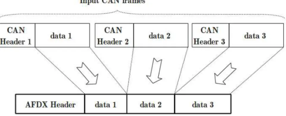
3.6 Packing CAN messages into AFDX frames . . . 55
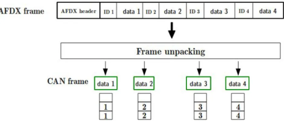
3.7 Frame unpacking process . . . 56
3.8 FWT frame packing strategy for upstream flows . . . 59
3.9 MSP frame packing strategy on upstream flows . . . 60
3.10 Mapping table for enhanced RDC device . . . 61
3.11 Structure of AFDX payload (ARINC 664) . . . 62
3.12 Chosen AFDX payload structure . . . 62
3.13 Explicit AFDX frame structure . . . 63
3.14 Implicit AFDX frame structure . . . 63
3.15 Hierarchical Traffic Shaping structure . . . 66
4.1 CAN-AFDX network architecture . . . 69
4.2 Upstream flows modeling from end-to-end . . . 70
4.3 Downstream flows modeling from end-to-end . . . 70
4.4 Example of CAN messages mapping onto AFDX VLs . . . 71
4.5 Example of AFDX VLs allocation under FWT strategy . . . 73
4.6 Example of AFDX VLs allocation under MSP strategy . . . 75
4.7 End-to-end delay metric definition . . . 76
4.8 Worst-case waiting time under FWT strategy . . . 78
4.9 Worst-case waiting time under MSP strategy . . . 79
4.10 Comparison between exact WCRT and upper bound (Example 2) . . . 84
4.11 Test case 1: one sensors CAN bus interconnected to the AFDX . . . 87
4.12 Test case 2: one sensors/actuators CAN bus interconnected to the AFDX . 88 4.13 CAN WCRT of upstream flows . . . 94
4.14 CAN WCRT of downstream flows . . . 94
5.1 Optimization for FWT strategy . . . 99
5.2 Impact of the waiting timer ∆ on the AFDX bandwidth consumption . . . . 100
5.3 Optimization for MSP strategy . . . 102
5.4 Bandwidth-Best-Fit Decreasing heuristic . . . 105
5.6 Optimization for HTS mechanism . . . 110
5.7 Example with the HTS heuristic approach (scenario 1) . . . 112
5.8 Example with the HTS heuristic approach (scenario 2) . . . 113
5.9 CAN WCRT of downstream flows . . . 116
6.1 CAN-AFDX case study . . . 120
6.2 AFDX network architecture (Courtesy of: ARTIST2 - IMA A380) . . . 121
6.3 Impact of FWT frame packing strategy on AFDX bandwidth consumption . 123 6.4 Impact of MSP frame packing strategy on AFDX bandwidth consumption . 124 6.5 Bandwidth Utilization on the AFDX with shared I/O network . . . 126
6.6 WCRT on CAN of upstream flows with shared I/O network . . . 127
6.7 Impact of HTS mechanism on AFDX bandwidth consumption . . . 128
A.1 Examples of Input and Output cumulative functions . . . 138
A.2 Arrival curve . . . 139
A.3 Example of leaky bucket arrival curve . . . 139
A.4 Example of rate latency service curve . . . 140
A.5 Backlog and delay bounds . . . 141
A.6 δT service curve . . . 143
A.7 WOPANETS Structure . . . 145
A.8 The Input Topology of the Case Study . . . 147
A.9 Maximal Delay Bounds Histogram (1Gbps) . . . 148
A.10 Tool run time as a function of the number of hops and flows . . . 149
B.1 TTCAN matrix cycle . . . 152
B.2 Example of TTCAN matrix obtained using TDMA scheduling . . . 153
B.3 Example of TTCAN matrix obtained using PSPQ scheduling . . . 154
B.4 FWT strategy for TTCAN I/O network . . . 155
B.5 MSP strategy for TTCAN bus . . . 157
B.6 Worst Case Response Time on TTCAN . . . 159
B.7 TTCAN bus interconnected to the AFDX . . . 160
List of Tables
4.1 Example 1: traffic characterization . . . 82
4.2 Example 1: exact WCRT vs upper bound . . . 83
4.3 Upstream flows description . . . 88
4.4 Downstream flows description . . . 89
4.5 Upstream flows description . . . 89
4.6 VLs characteristics under FWT . . . 90
4.7 End-to-end delay bounds under (1:1) strategy . . . 90
4.8 End-to-end delay bounds under FWT strategy with ∆1, ∆2 and ∆3 . . . . 91
4.9 MSP configurations considered for upstream flows in Table 4.3 . . . 91
4.10 Induced VLs characteristics under MSP configurations . . . 92
4.11 End-to-end delay bounds under MSP strategy . . . 92
4.12 Example 1: AFDX bandwidth consumption . . . 94
5.1 Comparative analysis of Optimization approaches . . . 104
5.2 Comparison between the optimization approaches for MSP configuration . 114 5.3 Impact of frame packing strategies . . . 115
5.4 Impact of HTS mechanism . . . 117
6.1 AFDX flows description . . . 121
A.1 Periodic Traffic Description . . . 147
A.2 Aperiodic Traffic Description . . . 148
B.1 Upstream flows description . . . 160
B.2 VLs characteristics under FWT for TTCAN . . . 161
B.3 End-to-end delay bounds under FWT strategy with ∆ = 1ms . . . 161
B.4 MSP configurations . . . 162 B.5 TTCAN-AFDX RDC: schedulability test and AFDX bandwidth consumption162
Introduction
Context and Motivation
The complexity of avionics communication architecture has increased rapidly due to the growing number of interconnected avionic systems and the expansion of exchanged data quantity. To follow this trend, the current architecture of new generation aircraft like the A350 consists of a high rate backbone network based on the AFDX (Avionics Full Duplex Switched Ethernet) [1] to interconnect the critical systems. Then, sensors and actuators are organized into one or more sensors/actuators networks based on low rate data buses like ARINC 429 [2] and CAN [3]. The obtained clusters are then intercon-nected via specific devices, called Remote Data Concentrators (RDCs) and standardized as ARINC 655 [4]. RDCs are modular gateways distributed throughout the aircraft to handle heterogeneity between AFDX-based backbone and peripheral data buses. The in-troduction of the RDC device aims mainly to reduce necessary cabling and to enhance the system modularity, with reference to prior network architectures. However, using RDC devices within the multi-cluster avionic networks raises challenging questions related to the impact of the RDC system performance in terms of network utilization.
The related work on the design and optimization of multi-cluster networks for avionics and automotive, and especially interconnection devices highlight the limitations of exist-ing solutions in terms of resource management. In particular, the current RDC device implements a simple frame conversion strategy which consists in forwarding one frame on the destination network for each incoming frame from a source network. Due to frame size and data rate dissimilarities between network clusters, this frame conversion strategy may induce high communication overheads on the interconnected networks. Furthermore, current RDC device connects exactly one sensors/actuators network to the avionic back-bone network which may imply an important number of RDC devices, and consequently inherent development and integration cost. Hence, the current RDC device offers the advantage of being simple to design and to configure; however, it is limited in terms of network resource savings, and it may induce additional system costs.
Introduction
The objective of this thesis is to design and validate an enhanced RDC device for multi-cluster avionics networks, which integrates network resource savings techniques and meets timing constraints. To achieve this goal, we consider a CAN-AFDX case study as a representative avionic multi-cluster network, and we integrate new elementary functions within the RDC device. First, our proposed RDC implements a frame packing function to minimize the consumed AFDX bandwidth by an I/O CAN network. Then, a traffic shaping function is implemented in the RDC to isolate sensors flows from actuators flows on an I/O CAN bus. Furthermore, our proposed RDC allows the interconnection of multi-ple CAN buses to the AFDX backbone, while enforcing the segregation between different criticality levels using a partitioning mechanism compliant with ARINC 653 specifications [5]. The performance of our proposed CAN-AFDX RDC is evaluated using an analytical framework to prove the offered real-time guarantees when considering the nominal case of communication.
The tuning of our proposed RDC device is addressed to achieve the best RDC config-uration, i.e., parameters of RDC minimizing the network resources utilization and guar-anteeing the schedulability of communication. The RDC tuning problem is formulated as an optimization problem where: (i) the RDC frame packing and traffic shaping pa-rameters are the variables; (ii) minimizing the AFDX bandwidth consumption due to the RDC device is the objective; (iii) the schedulability of communication flows crossing the CAN-AFDX network corresponds to the constraints. However, this optimization problem is considered as a NP-hard problem. Hence, to solve this latter in a polynomial time, we introduce heuristic approaches to find the accurate RDC configuration which maximizes resource savings.
The validation of our proposed RDC is done through a realistic case study under dif-ferent load conditions. The analysis is conducted based on our developed tool WoPANets [6] which is able to analyze AFDX and CAN networks when integrating the impact of the different additional functions, i.e., frame packing and traffic shaping, within our proposed RDC device. The end-to-end latencies and the AFDX bandwidth consumption for the considered avionics CAN-AFDX network using our proposed RDC device are computed. The obtained results showed the efficiency of the frame packing process when applied for upstream flows to minimize AFDX bandwidth consumption. Moreover, the use of the traffic shaping mechanism when applied for downstream flows, combined with the frame packing process, has shown an interesting improvement of bandwidth utilization savings (up to 40%).
Original Contributions
Original Contributions
Our main contributions are as following:
– Design of an enhanced CAN-AFDX RDC device: the proposed RDC device consists of configurable elementary functions and it is capable to connect multiple I/O CAN buses to the AFDX backbone. The frame packing function is integrated to reduce communication overheads on the AFDX, with reference to a simple (1:1) frame conversion strategy, by grouping multiple CAN frames within the same AFDX frame. Moreover, a traffic shaping mechanism, called ”Hierarchical Traffic Shap-ing” (HTS), is implemented in our proposed RDC device to isolate upstream and downstream flows on CAN bus, and consequently to favor frame packing process. Furthermore, our proposed RDC device is capable of interconnecting multiple I/O CAN buses to the AFDX backbone, while isolating data flows from different CAN buses by using partitioning technique compliant with ARINC 653 specifications [5]. This partitioning mechanism offers segregation between flows from different critical-ity levels and simplifies the data mapping process in the RDC device.
– Performance analysis of the enhanced CAN-AFDX RDC device: to prove the offered real-time guarantees and the capacity of our proposed RDC to save net-work resources, we introduce an analytical approach to evaluate the worst-case per-formance of a CAN-AFDX network interconnected using our enhanced RDC device. First, the modeling phase of the CAN-AFDX network including our proposed RDC device is described. Then, a timing analysis is introduced to evaluate the impact of the introduced functions within the RDC device on the communication performance. – Optimization of CAN-AFDX RDC parameters: heuristic methods and algo-rithms for RDC device tuning are provided to increase as much as possible network efficiency in terms of AFDX network bandwidth consumption, which is considered as a relevant metric to assess network resource savings. First, we consider the case of specific CAN buses for either sensors or actuators to evaluate the impact of frame packing strategies on AFDX bandwidth consumption. Then, we consider the gen-eral case where an RDC device can support many I/O CAN buses interconnecting both sensors and actuators. The impact of the contention between upstream and downstream flows on AFDX bandwidth consumption is integrated.
Thesis Outline
– Validation of the enhanced RDC device: The validation of RDC capacity to save network resources and to meet avionics requirements is done through a realis-tic case study under different load conditions. The considered CAN-AFDX network includes several I/O CAN buses and an AFDX backbone with hundreds of AFDX flows. The interconnection of CAN buses to the AFDX is done using our enhanced RDC device. A performance evaluation is conducted under different test cases to highlight the ability of our proposed RDC device to save resources and to guarantee real-time constraints.
Thesis Outline
This thesis consists of six chapters. Chapter 1 gives an overview of the avionic context and the main requirements. First, a brief history of avionic architectures and the appearance of multi-cluster communication networks are described. Then, the main avionic network technologies are presented, and particularly the main features of AR-INC 655 standard [4] for RDC devices. Finally, the design opportunities of multi-cluster avionic networks are discussed, and especially the impact of RDC devices on real-time performances of avionic networks.
Chapter 2 presents the most relevant work related to the design and the optimization of multi-cluster avionics network. This state of the art covers different aspects varying from optimizing the performance analysis of the AFDX backbone and sensors/actuators networks, to tuning the traffic source mapping and interconnection devices configuration. Then, the main motivations and challenges to design and optimize the RDC device for CAN-AFDX network are detailed.
In Chapter 3, we introduce an enhanced CAN-AFDX RDC device. The proposed RDC consists of a set of elementary functions which aims to improve the RDC per-formance, with reference to the currently used RDC device. First, an overview of the functional structure of the enhanced RDC device is provided. Then, the integrated ele-mentary functions within the RDC device are detailed, such as frame packing and traffic shaping functions.
In Chapter 4, to evaluate the timing performance of our proposed RDC device and to verify communication schedulability, we model the CAN-AFDX network architecture
Thesis Outline including the enhanced RDC device. Then, a timing analysis process taking into account the impact of the new functions integrated into the RDC device on the communication performance is provided. Then, preliminary performance analysis is conducted through small scale test cases to estimate the offered network resource savings and to prove the real-time guarantees of our proposed RDC device.
Since many RDC configurations may be schedulable while offering different levels of re-source savings on CAN-AFDX networks, we address in Chapter 5 the tuning of the RDC device to achieve the best configuration, i.e., the parameters of the RDC functions mini-mizing the network utilization while meeting the time constraints. The tuning process of our proposed RDC device is first formulated as an optimization problem. Then, adapted heuristic approaches to find optimal RDC configuration are detailed. Afterwards, prelim-inary results obtained using the optimized CAN-AFDX RDC device with small scale test cases are provided.
In Chapter 6, to validate our proposed CAN-AFDX RDC device, we consider a re-alistic avionics case study with various load conditions. The end-to-end latencies and the AFDX bandwidth consumption induced by our proposed RDC device are computed. Then, a comparative study between different RDC configurations and under various traf-fic load conditions is conducted to highlight the capacity of our proposed RDC device to save network resources, while meeting the hard real-time constraints of the avionics applications.
Finally, we conclude with a discussion about the performance of our enhanced RDC device. Then, we present some directions that can be explored in the future.
Chapter 1
Background and Problem Statement
In this chapter, an overview of the evolution of avionic architectures and the appear-ance of multi-cluster avionic networks are first presented. Afterward, the main network technologies used in these architectures are described. Then, the ARINC 653 standard [4] for interconnection devices is presented from functional and architectural perspectives to highlight its role in multi-cluster avionic networks. Finally, the main design opportunities for multi-cluster avionic networks are discussed.
1.1
Progress of Avionic Communication Architecture
and Main Challenges
To handle the increasing needs of avionic systems in terms of computing and In-put/Output resources, the avionic architecture has evolved from federated architecture [7], i.e., functions are hosted by dedicated hardware, to Integrated Modular Architecture (IMA) [7], i.e., functions share common hardware modules (e.g. CPU module, I/O mod-ule). As a part of the avionic architecture, the communication networks have also evolved from low rate dedicated data buses (e.g. ARINC 429 [2]) to multiplexed field-buses (e.g. MIL-STD-1553B [8], ARINC 629 [9], CAN [3]), and more recently switched networks, e.g. ARINC 664 [1]. Although this progress offers a more scalable architecture to support dis-tributed avionic functions, it has raised at the same time several challenges related mainly to the system’s performance and resources utilization. In this section, we first present an overview of avionic architecture evolution. Afterwards, we focus on multi-cluster net-works, used in modern aircraft to support communication between avionic end-systems, and we identify their main challenges.
Chapter 1. Background and Problem Statement
1.1.1
History of Avionic Architecture
At the beginning of aircraft’s industry, avionics functions were hosted by dedicated hardware with their proper processing units, which are directly attached to their In-put/Output interfaces to get required data and perform some computations. Then, pro-cessed data are exchanged with other avionic functions. This avionic architecture, called federated architecture, has been used for decades for avionics systems to support safety-critical functions and to guarantee system’s requirements. This avionic architecture offers a high isolation level due to the dedicated hardware, i.e., dedicated processing resources and I/O interfaces. However, with the increasing number of avionic functions, the feder-ated architecture reached its limits due to the important number of required hardware, and consequently inherent system weight and costs.
In the last two decades, Integrated Modular Architecture (IMA) has been introduced as an alternative to federated architecture. The IMA concept consists in using a set of common hardware modules (e.g. CPU module, I/O module) to support several appli-cations with different safety levels. Hence, the system’s resources have became shared between several avionic functions, while isolation is still guaranteed at the software level using partitioning techniques. For instance, the ARINC 653 [5] standard specifies a par-titioning mechanism, which provides isolation between avionics functions hosted within the same avionics system. This isolation is achieved by restricting the address space of each partition and limiting the amount of CPU time reserved for each partition. The objective is to ensure that an errant avionics function running in one partition will not affect functions running in other partitions
As the avionic architecture evolved, the avionic communication system has also evolved to follow the increasing demand on communication resources and the emerging require-ments of IMA architecture. Using federated avionic architecture implied a low exchanged data between subsystems, and consequently using point-to-point connections, such as AR-INC 429 [2] bus standard, was efficient. However, with the IMA approach, an increasing number of avionic functions and exchanged data quantity have to be supported. Hence, the ARINC 429 bus became no longer effective due to its low data transmission rate and high required cabling. Therefore, new communication standards have been introduced to meet these emerging requirements with IMA architectures. For instance, AFDX [1] stan-dard, based on Switched Ethernet at 100 Mbps was introduced by Airbus in the A380 as a high speed backbone network.
1.1. Progress of Avionic Communication Architecture and Main Challenges
1.1.2
Appearance of Multi-cluster Avionic Networks
In this section, we first present the main avionics requirements. Then, we review the recent progress of the avionic communication networks, used with IMA architecture.
1.1.2.1 Avionics Requirements
The avionic network as a part of the avionics system has to fulfill a set of requirements [10]. The main ones are as follows:
– Predictability: The avionic network must behave in a predictable way and ap-propriate proofs to guarantee its determinism have to be provided by the network designer. For example, the communication latencies, the backlog in a network node or the packet loss rate have to be bounded. The required proof depends on the avionics application. For instance, consider an air pressure sensor that produces a measurement each 10 ms and sends it through the avionic network to one or many calculators to perform some computations. To meet predictability requirement, a network designer can check that each pressure measurement is delivered to its des-tinations within 10 ms from its production instant to its end of reception at the calculator. Moreover, the average loss rate of pressure measurements may also be assessed to estimate the calculation quality.
– Reliability: The avionic network must be fault-tolerant and fulfill minimum safety levels. One aspect related to the avionics system reliability consists in preventing failed nodes in the network from affecting the normal operations. Several mecha-nisms can be used to improve the reliability and the robustness of the communication network in avionics context. It is common to use multiple redundant data paths to enhance the network fault tolerance, such a mechanism is supported by the AFDX protocol [1]. Moreover, retransmission mechanisms can be implemented inside net-work nodes to recover packet losses. Furthermore, redundant nodes can be used to recover and replace a faulty node during operation time.
– Modularity: This requirement is related to the flexibility and exchangeability of components between avionic systems. An important step towards enhancing the avionics system modularity has been taken by adopting IMA approach for avionic architecture design. Avionic systems consist of common elementary components, which can be configured to fit different avionic applications. The integration of such components requires well-defined hardware and software interfaces. The hardware
Chapter 1. Background and Problem Statement
configuration of avionic systems must allow easy maintenance. The modularity of avionic systems allows to exchange components and even systems with minimum configuration and readjustment effort. This fact facilitates system’s maintenance and future evolution, such as adding new avionics functions or replacing existing ones.
– Cost and life cycle: These requirements are related to the maintainability, man-ageability and direct costs associated with the avionics system development and maintenance. One important step towards reducing avionics system costs was done with the modular design introduced by the IMA approach. The flexibility and con-figurability of avionic systems reduce development cycle duration, and ease incre-mental design process and maintenance operations. Furthermore, the use of com-mercial off-the shelf (COTS) technologies and components, which are cheap and largely available, aims to reduce development and deployment costs of the avionics system. Although the use of COTS technologies in the avionics context required additional development effort due to the strict avionics requirements, this choice offers significant system’s cost reduction and it is currently an attractive alternative for aircraft manufacturers. The introduction of the AFDX [1] network protocol, based on Switched Ethernet, is a typical example on how COTS technologies may be adopted for avionics use with additional development effort to fulfill avionics re-quirements and to reduce costs.
1.1.2.2 Description and Main Challenges
The complexity of avionic communication architecture is increasing rapidly due to the growing number of interconnected subsystems and the expansion of exchanged data quantity. To follow this trend, the architecture of new generation aircraft, such as the A380, consists of a high rate backbone network based on the AFDX [1] to interconnect the critical subsystems, as shown in Figure 1.1. Then, each specific avionic subsystem is directly connected to its associated Input/Output (I/O) network based on low rate data buses, such as ARINC 429 [2] and CAN [3].
Although this architecture simplifies the design process and reduces the time to mar-ket, it leads at the same time to inherent weight and integration costs due the important number of sensors/actuators networks. In addition, this architecture makes the avionics subsystems closely dependent on their Inputs/Outputs and no longer interchangeable. However, for avionic applications, it is essential that the communication architecture
ful-1.1. Progress of Avionic Communication Architecture and Main Challenges
Figure 1.1: Avionic network architecture: dedicated I/O networks
fills the emerging requirements in terms of modularity and performance to guarantee an easy incremental design process and the possibility of adding new functions during the aircraft lifetime.
Figure 1.2: Centralized avionic architecture
On the other hand, as shown in Figure 1.2, systems connected using AFDX were centralized in the avionic bay. This fact implies high cabling quantities, since each I/O
Chapter 1. Background and Problem Statement
network requires dedicated cabling to communicate with its corresponding AFDX end-system. This cabling is done through long distances going generally from the aircraft wings and tail, where most of sensors and actuators are located, to the main avionic bay at the front of the aircraft.
Figure 1.3: Multi-cluster avionic network architecture
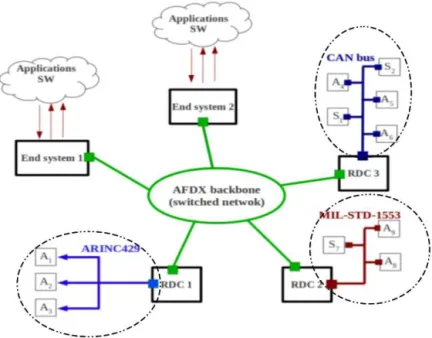
To handle these limitations, the solution, implemented in recent aircraft, such as A350 and A400M, consists in keeping the AFDX as a backbone network to interconnect the crit-ical avionic systems, and dissociating the sensors and actuators from their corresponding end-systems. As shown in Figure1.3, the obtained clusters are interconnected via specific devices, called Remote Data Concentrators(RDCs), and standardized as ARINC 653 [4]. RDCs are modular gateways distributed throughout the aircraft, as shown in Figure 1.4, to handle heterogeneity between the AFDX backbone network and peripheral data buses.
This alternative architecture enhances the avionic subsystems modularity and simpli-fies the reconfiguration process. The RDC actually becomes the main node that needs to be reconfigured in case of sensor or actuator modification. Furthermore, distributing RDC devices in the aircraft reduces considerably the required network cabling. However, at the same time it represents one of the major challenges in the design process of such multi-cluster avionic networks.
1.2. Description of Network Standards
Figure 1.4: Distributed avionic architecture
1.2
Description of Network Standards
In this section, we present the main features of the AFDX network used in current avionic architectures as a high speed backbone network. Then, we describe the main network technologies used for I/O networks: ARINC 429 and CAN.
1.2.1
ARINC 664: Backbone Network
The AFDX [1] network is based on Full Duplex Switched Ethernet at 100 Mbps, suc-cessfully integrated into new generation civil aircraft, such as the A380 and the A400M. This technology succeeds to support the important amount of exchanged data and to guar-antee timing requirements, due to its high data rate, its policing mechanism in switches and the Virtual Link (VL) concept.
1.2.1.1 Virtual Link
AFDX virtual link gives a way to reserve a guaranteed bandwidth to each traffic flow. The VL represents a multicast virtual channel which originates at a single end-system and delivers its packets to a fixed set of end-systems, as shown in Figure1.5. Each VL is characterized by: (i) BAG (Bandwidth Allocation Gap), ranging in powers of 2 from 1 to 128 milliseconds, which represents the minimal inter-arrival time between two consecutive
Chapter 1. Background and Problem Statement
Figure 1.5: Example of AFDX virtual links
frames; (ii) MFS (Maximal frame size), ranging from 64 to 1518 bytes, which represents the size of the largest frame that can be sent during each BAG. The VL control mecha-nism is illustrated in Figure1.6.
Figure 1.6: Virtual Link bandwidth control mechanism
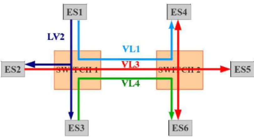
Using the VL control mechanism, a 100 Mbps Ethernet link can support multiple Virtual Links. For instance, in Figure 1.7 three Virtual Links are carried by a single Ethernet physical link. The figure also shows that the messages sent on AFDX Ports 1, 2, and 3 are carried as sub-VLs by VL 1. Similarly, messages sent on AFDX Ports 6 and 7 are carried by VL 2, and messages sent on AFDX Ports 4 and 5 are carried by VL 3.
1.2.1.2 Message flows & Frame Structure
The end-to-end communication of a message using AFDX requires the configuration of the source end-system, the AFDX network and the destination end-systems to deliver correctly the message to the corresponding receive ports. Figure 1.8 shows a message M being sent to Port 1 by the avionics subsystem. End system 1 encapsulates the message in an AFDX frame and sends it to the AFDX into the VL 100 (the destination addresses are specified by VLID 100). The forwarding tables in the network switches are configured
1.2. Description of Network Standards
Figure 1.7: Three AFDX Virtual Links carried by a 100 Mbps Ethernet link
Figure 1.8: Example of application data flow on AFDX
to deliver the frame to both end-systems 2 and 3. The end-systems are configured to be able to determine the destination ports for the message contained in the frame. In this case, the message is delivered by end-systems 2 and 3 to ports 5 and 6, respectively.
Chapter 1. Background and Problem Statement
Figure 1.9: AFDX frame format
An AFDX frame is based on the Ethernet frame, as shown in Figure1.9. The Ether-net header allows the identification of the source and destinations end-systems. The IP and UDP headers allow each destination end-system to find the corresponding destina-tion port for the received message within the Ethernet payload. The Ethernet payload consists of the IP packet (header and payload). Then, the IP packet payload contains the UDP packet (header and payload), which contains the message sent by the avionics applications. Padding is used only when UDP payload is smaller than 18 bytes, to ensure a minimum AFDX frame size of 64 bytes. The maximum frame size is 1518 bytes without counting the IFG (Inter-Frame Gap) of 12 bytes and the preamble of 8 bytes. This IFG and preamble have to be considered when performing timing analysis to take into account the overhead of data transmission over the AFDX network.
1.2.1.3 Application Layer: ARINC 653 Specifications
As shown in Figure1.10, an avionics system is connected to the AFDX network through an end-system. In general, an avionics system is capable of supporting multiple avion-ics subsystems. A partitioning mechanism, compliant with ARINC 653 [5] specifications, provides isolation between avionics subsystems within the same avionics system. This iso-lation is achieved by restricting the address space of each partition and by placing limits on the amount of CPU time reserved for each partition. The objective is to ensure that an errant avionics subsystem running in one partition will not affect subsystems running on other partitions.
Hence, avionics applications are assigned to ARINC 653 partitions and communication between them is ensured using communication ports. In the example of Figure1.11, three AFDX end-systems communicate through an AFDX network. Each end-system runs two
1.2. Description of Network Standards
Figure 1.10: ARINC 653 partitioning for AFDX end systems
partitions which host avionics applications. Partition 1 of end-system 1 communicates with partition 1 of end-system 2 using partitions ports (source port 1 of partition 1 of end-system 1 and destination port 2 of partition 1 of end-system 2). As we can see from this example, data flows originated from the same ARINC 653 partition in an AFDX end-system can share the same VL at the MAC layer. However, data flows from different partitions are not allowed to share VLs to guarantee segregation between partitions on AFDX network.
1.2.2
Sensors/Actuators Networks
1.2.2.1 ARINC 429
The ARINC 429 standard [2] is a widely used avionic data bus that has been deployed in various avionic applications for decades. This standard relies on unidirectional commu-nications with a single transmitter and up to twenty receivers. Connected devices, Line Replaceable Units (LRUs), can be organized in a star or bus topologies as shown in Figure
1.12. Each LRU may host multiple transmitters or receivers communicating on different ARINC 429 buses. This simple architecture of ARINC 429 bus offers a highly reliable
Chapter 1. Background and Problem Statement
Figure 1.11: Communication from application to application over AFDX with ARINC 653 communication with short transmission latencies.
ARINC 429 data transfer is based on 32 bit data word, as described in Figure 1.13. ARINC 429 data words are made up of five primary fields:
– Parity (1 bit): allowing error check to guarantee accurate data reception;
– Sign/Status Matrix (SSM) (2 bits): can be used to indicate the sign or direction of the words data, or to report source equipment operating status. This field is dependant on the data type;
– Data/Payload (19 bits): containing the word’s data information;
– Source/Destination Identifier (SDI) (2 bits): indicating which source is transmitting the data or for which receivers the data is destined;
1.2. Description of Network Standards
Figure 1.12: ARINC 429 network architectures
or data reporting information. Labels may be further refined using the first 3 bits of the data field as an Equipment Identifier to identify the source.
ARINC 429 specifies two speeds for data transmission: high speed operates at 100 Kbit/s and low speed operates at 12.5 Kbit/s. ARINC 429 operates in such a way that each single transmitter communicates in a point-to-point connection with its receivers. This fact requires an important amount of cables which significantly increases the overall aircraft weight. This traditional data bus is no longer effective in meeting the emerging requirements of avionic applications in terms of throughput demand and modularity.
Chapter 1. Background and Problem Statement
1.2.2.2 CAN
The Controller Area Network (CAN) data bus was designed in the 80s by Robert Bosh GmbH [3] for automotive applications. Its success due to its reliability and its versatility attracted the attention of manufacturers in other industries, including process control, medical equipment, and recently avionics.
The CAN bus operates at data rates up to 1Mbps for cable lengths less than 40m, and 125Kbps when the length is around 500m. Two versions of the CAN protocol are specified: CAN 2.0 A and CAN 2.0 B. The first uses the standard frame format, that supports a 11-bit identifier, while the second uses an extended frame format in which the identifier consists of 18 additional bits (for a total of 29 bits). Controllers connected to the CAN bus must transmit and receive data while avoiding collisions using the Carrier Sense Multiple Access with Collision Resolution (CSMA/CR) mechanism.
– Message arbitration: a bus terminal can start a new transmission only when the bus is idle. However, if two terminals try to transmit at the same time, then an arbitration protocol is implemented to allow the transmission of the message with the highest priority (Arbitration based on Message Priority or AMP).
Figure 1.14: CAN protocol: CSMA/CR access mechanism
The bus signal can have two logic values, dominant and recessive: whenever two terminals attempt a simultaneous transmission of a dominant bit and a recessive bit, a dominant logic value will result on the bus. In a typical implementation of a wired connection 0 is the dominant value, and consequently this is often called an AND implementation. As shown in Figure 1.14, the first controller that loses the contention, i.e., sending a recessive bit and reading a dominant value resulting on
1.2. Description of Network Standards the bus, must immediately stop its transmission. This fact results in an arbitration technique based on the message header, which determines the communication pri-ority. CAN is based on broadcast communications where each transmitted frame is received by all the connected terminals. Each node will determine if the received frame is relevant to that particular system or not, and drop packets that were not addressed to it.
– Frame structure as shown in Figure 1.15, CAN data frames consist of a payload up to 8 bytes and an overhead of 6 bytes due to the different headers and bit stuffing mechanism.
Figure 1.15: CAN 2.0 A frame structure Each CAN frame consists of the following bit fields:
– Start Of Frame (SOF) (1 bit): is always a dominant bit marking the beginning of a transmission;
– Arbitration (13 bits): consists of the Identifier, the Remote Transmission Request (RTR) for a standard frame (or the Substitute Remote Request (SRR) for an extended frame), and finally the Extension bit IDE to determine if the frame is standard or extended. It identifies the type of CAN message and defines its transmission priority on CAN bus;
– Control (5 bits): is composed of r0and r1, reserved bits that are always dominant;
and the Data Length Code (DLC) of 4 bits, which specifies the number of bytes present in the Data field;
– Data (1-64 bits): contains the actual information; – CRC (16 bits): is used to guarantee data integrity;
Chapter 1. Background and Problem Statement
– End Of Frame (EOF) ( 7 bits): indicates the end of the CAN frame;
– Intermission Frame Space (IFS) (3 bits): is the minimum number of bits separat-ing consecutive messages. Durseparat-ing this intermission period no other communica-tion can start on the CAN bus.
To ensure a strong synchronisation, the protocol avoids the presence of more than 5 consecutive bits of the same value in the transmitted frame by adding a stuffing bit with the opposite value. Stuff bits increase the maximum transmission time of CAN messages. Including stuff bits and the inter-frame space, the maximum transmission time Cm of a CAN message m including bm data bytes were proven in [11] and are
given by the following expressions: – for 11-bit identifiers,
Cm= (55 + 10∗ bm)∗ τbit (1.1)
– and for 29-bit identifiers,
Cm= (80 + 10∗ bm)∗ τbit (1.2)
where τbit is the transmission time for a single bit.
1.3
Description of RDC Standard: ARINC 655
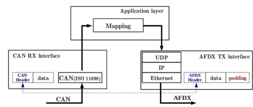
The Remote Data Concentrator (RDC) [4] is a gateway that performs protocol conver-sion to guarantee interoperability between avionic systems with different communication interfaces and specific communication protocols. Typically, it translates data from various sources, e.g. sensors and actuators, into a format usable by avionic computing resources. It also converts data from computing resources into appropriate formats usable by various sensors and actuators equipments. ARINC 655 standard [4] was introduced as a high-level design guide for RDCs. It mainly reviews the requirements to fulfill by RDC devices for avionic networks. Moreover, it provides guidelines concerning the design of RDC devices.
1.3.1
RDC Requirements
The RDC device inherits from avionics requirements described in Section1.1.2.1 and particularly:
1.3. Description of RDC Standard: ARINC 655
– Predictability: the process of reception and transmission of data by the RDC device introduces additional network latency. For critical avionics applications, the system designer must ensure that the end-to-end data latency is less than the re-quired deadline. Therefore, it is important to determine the permissible latency for each system that uses this information at the beginning of the design process. – Reliability: the designer of RDC device should consider a fault tolerant design.
The level of fault tolerance is determined by the analysis of the system integrity goals, the required availability of the function and the overall maintenance proce-dure.
– Modularity: RDC device should be modular, i.e., composed of standard modules that can be easily replaced. RDC devices should be exchangeable and reconfigurable, such that the replacement of a RDC device does not require long and complex ad-justments.
– Cost and life cycle: network designer should consider minimizing the different types and number of required RDCs for an avionic network. This fact aims at reducing manufacturing costs, by reducing the system weight and simplifying its development.
Furthermore, an RDC device has to meet some additional requirements related to its role as an interconnection device:
– Interoperability: the primary purpose of an RDC device is to ensure interoper-ability of avionic systems of different manufacturers. Appropriate network interfaces should be integrated into the RDC and data formats conversion functions should be implemented to guarantee communication transparency between avionic systems. The mapping of packets format has to be ensured between a source and a destina-tion network interconnected by the RDC device.
– Adaptability: the RDC should be able to interface with a variety of data buses and other network technologies used in aircraft. The RDC should be configurable to be customized for different interconnection applications with different performance requirements.
Chapter 1. Background and Problem Statement
– Resources utilization efficiency: the RDC should keep communication over-heads as low as possible when forwarding data flows from a source to a destination network. This fact saves network resources and keeps margins for the future evolu-tion of the avionic architecture.
To meet the main RDC requirements, the ARINC 655 specifications provide some recommendations and guidelines which can be grouped into two categories: functional and architectural. These specifications will be detailed in the next sections.
1.3.2
Functional Specifications
The RDC device should include appropriate functions to receive, process and forward data from typical avionic I/O networks to the processing computers and vice versa. The main functions that should be integrated into the RDC device are:
– Data Mapping: the RDC should perform the conversion of the received data for-mat to fit the target network forfor-mat. A configurable mapping table should be used to map data type and address to fit the requirements of the destination networks. The mapping table should be static and well configured to guarantee the required safety and timing performance levels. Furthermore, as several RDCs devices may be used within the same network, a consistent mapping process should consider all the mapping tables in RDC devices;
– Data Forwarding: the RDC should forward data received from an input network interface to one or several output interfaces. The RDC may be used to connect two or more network clusters. Therefore, a forwarding function is required to define for each received data the output interfaces. A simple solution consists in using a static forwarding table that is configured offline in the RDC device by the network designer; – Data processing: the RDC may include software functions, such as data sampling, filtering and monitoring. These software functions may also perform range checking, data validity and fault detection. These functions may increase end-to-end commu-nication latencies, and should be taken into account during the timing analysis and the validation of the RDC behavior.
1.3. Description of RDC Standard: ARINC 655
1.3.3
Architectural Specifications
Figure 1.16: Synchronous mode for CAN-AFDX RDC The main RDC’s architectural recommendations are:
– Communication scheme: two communication schemes are described in ARINC 653 specifications:
– Synchronous RDC: in this case, the processing and forwarding of a received data by the RDC is triggered by the event of data reception. An example of a syn-chronous CAN-AFDX RDC is shown in Figure 1.16.
– Asynchronous RDC: in this case, the rates and instants of data exchanges between the RDC and connected networks are determined by the RDC. The RDC imple-ments a write/read table where data from different equipimple-ments communicating with the RDC are gathered. An example of an asynchronous CAN-AFDX RDC device is shown in Figure 1.17. For each type of messages, a received message in the RDC overwrites the old one and a binary freshness indicator is used. The transmission of data flows is done periodically with transmission rates defined in the RDC. One significant advantage of this asynchronous mode consists in adapt-ing data rates between the source producadapt-ing and the destinations receivadapt-ing data. For example, consider a sensor producing the air pressure measurement each 2 ms. Consider computing systems consuming this data to perform a computation
Chapter 1. Background and Problem Statement
once each 10 ms. Since sensor data is produced at a higher rate than the required one, then the RDC may adapt production rates by reading the pressure data from its write/read memory once each 10 ms.
Figure 1.17: Asynchronous mode for CAN-AFDX RDC
– Partitioning: the RDC should interconnect multiple sub-networks which may have different levels of criticality. Therefore, a partitioning process should be used in the RDC to keep isolation between communication flows having different criticality lev-els.
1.4
Design Opportunities for Multi-Cluster Avionic
Networks
As described in Section1.1.2.2, the main benefits of multi-cluster avionic networks are the use of old equipments with new ones, and the reduction of weight and I/O resources. For instance, the use of RDC devices allows cabling reduction, and enhances the modu-larity and exchangeability of the avionic end-systems.
However, the use of multi-cluster networks in the avionics context arises mainly the following challenges:
1.4. Design Opportunities for Multi-Cluster Avionic Networks – Software/Hardware (SW/HW) Mapping: the avionics system consists of a set of applications which need to exchange data; and a set of communicating nodes via data buses or other network technologies. Each node can host one or multi-ple applications. The mapping of applications onto network nodes is an important task when designing the avionics networks. This mapping will clearly impact the resource utilization and real-time performance of the avionics system, and it has to be considered during network integration phase. Hence, the designer should select the SW/HW mapping maximizing the resource savings while meeting real-time re-quirements.
– End-to-end communication performance: avionics networks have to fulfill real-time constraints requirements. Bounding the total delay of each data from a source to one or many destination nodes is an important issue to fulfill the predictabil-ity requirement, and particularly the stabilpredictabil-ity for closed loop control in avionics. In multi-cluster networks, the latency between data input and its corresponding output are due to: (a) communication latency through network clusters (e.g. data buses and backbone networks); (b) interconnection latency due to the traversal of gate-ways. These delays depend on the scheduling policies used in the network nodes (e.g. source and destination end-systems, switches and gateways), and the observed con-tentions on shared networks. Hence, appropriate modeling and analysis techniques should be used to prove that the avionics network meets the real-time requirements. – Design of interconnection device and interoperability issues: the intercon-nection devices have a major importance in multi-cluster avionics networks, since they allow heterogeneous network technologies to exchange data and to keep end-to-end connectivity between avionics systems. The RDC [4] is an avionics interconnec-tion device used typically to connect sensors/actuators networks with the backbone network connecting computing units. Therefore, the RDC device has: (i) to ensure frame formats conversion and consistent addressing of data packets between source and destination networks; (ii) to offer bounded latency and a predictable behaviour; (iii) to ensure the isolation of data flows with different criticality levels. Further-more, the inter-cluster communication through the RDC device may induce high communication overheads due to the dissimilarities between interconnected network clusters in terms of rates and frame formats. Hence, the impact of RDC device on resource utilization has to be considered, and design choices reducing the commu-nication overheads between interconnected networks should be integrated.
Chapter 1. Background and Problem Statement
1.5
Conclusion
Current civil avionic communication architecture consists of several network clusters, interconnected using RDC devices standardized under the ARINC 655. These multi-cluster networks present the advantage of allowing the use of old data buses in conjunction with new network technologies, such as the AFDX protocol. This fact reduces develop-ment costs of new equipdevelop-ments and guarantees the incredevelop-mental design of avionics systems. However, the performance optimization of multi-cluster avionic networks arise several challenges, which are mainly due to: (i) the difficulty of performing software/hardware mapping; (ii) the complexity of performance analysis and meeting the real-time con-straints; (iii) the design of interconnection devices and interoperability issues.
In the next chapter, we present the main related work on performance optimization for multi-cluster embedded networks, and especially the main existing work dealing with the interconnection devices.
Chapter 2
Related Work: Performance
Optimization for Multi-Cluster
Networks
In the area of performance optimization for embedded networks in avionics and au-tomotive, various approaches have been integrated into different parts of the end-to-end communication path, including traffic sources, communication networks and interconnec-tion devices. We review in this chapter the most relevant work in this area for avionics and automotive applications. First, we present optimization approaches for traffic-source mapping, where the main concern is the mapping of the application data onto frames. Then, main existing approaches for performance optimization for communication net-works are detailed, including, timing analysis and data routing for both AFDX and sen-sors/actuators networks. Finally, the optimization of interconnection devices is reviewed and existing protocol conversion approaches to guarantee real-time performance and re-source utilization efficiency are detailed.
2.1
Optimizing Traffic-Source Mapping
Traffic-source mapping consists in affecting data produced by a source application to the frames supported by the communication network. A simple mapping consists in in-cluding each generated data into a dedicated frame. However, this choice may induce a high communication overhead. A more advanced mapping approach consists in grouping multiple data produced by one or many applications in the same network frame. The traffic-source mapping has a direct impact on the network utilization. The grouping
pro-Chapter 2. Related Work: Performance Optimization for Multi-Cluster Networks cess of elementary data allows reducing the protocol overheads, and consequently saving network capacity and improving communication efficiency. Different strategies have been introduced for avionics end-systems and automotive ECUs (Electronic Control Units) and have shown significant enhancements in terms of network capacity utilization.
2.1.1
Avionics End-Systems
The AFDX network is considered as a promising communication technology for mod-ern avionics architectures. The AFDX is based on routing frames through isolated data channels, called Virtual Links (VLs).
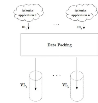
In [12], the authors introduced a method to define VLs characteristics to minimize the AFDX network utilization rate. The method presented in [12] is illustrated in Figure
2.1 and it consists in packing data from different AFDX applications hosted by the same AFDX end-system within the same AFDX frame. The transmission of each resulting AFDX frame is supported by an AFDX VL respecting the frame characteristics. The authors in [12] proposed an approach to find VLs configuration minimizing the band-width consumption on AFDX network to improve network resources utilization and to ease the addition of new VLs. First, an algorithm to find the optimal VLs allocation for periodic or sporadic data generated by the same AFDX application was proposed. This algorithm is based on data segmentation and has as objective minimizing the consumed bandwidth on the AFDX network. Afterwards, this algorithm was extended to find the optimal allocation for a set of data generated by the same end-system. The applicability of this approach was illustrated on a representative avionics benchmark, and the results showed its efficiency to save network bandwidth utilization. However, this approach did not integrate the verification of the time constraints.
Another interesting work in this area was presented in [13]. This work concerns the adequate mapping of avionics functions onto processing modules while meeting real-time and resource constraints. Avionics applications are hosted by partitions compliant with ARINC 653 [5]. Each partition has its own memory space and it is executed periodically during a reserved time slot. As illustrated in Figure 2.2, two partitions P1 and P2 are
executed on the same processing unit with respect to their associated periods. The period of the obtained schedule is called the Major Frame (MAF).
In [13], the authors formulated an optimization problem for mapping avionics par-titions onto processing resources of an IMA architecture. The formulation takes into
2.1. Optimizing Traffic-Source Mapping
Figure 2.1: Data packing and VLs allocation
Figure 2.2: Periodic execution of Partitions
account resources as well as timing constraints of mapped avionics functions. The main objective was to maximize the evolution margins and to ease future avionics functions addition to the system. A method to solve this optimization problem was provided. However, this mapping problem considered only AFDX communication network, and the impact of an interconnected communication network, as currently used in avionics, on the software/hardware mapping was not considered.