Ministry of Higher Education and Scientific Research Ferhat Abbas, Setif 1 University Institute of Optics and Precision
Mechanics
1فيطس سابع تاحرف ةعماج ةقدلا كيناكيم و تايرصبلا دهعم
Abstracts book
3rd International Conference o
n Mechanics and
Materials
ICMM’2019
11-12 November 2019. Setif, Algeria,
The Institute of Optics and Precision Mechanics of Ferhat Abbas University
Setif 1, Algeria organizes the third International Conference on Mechanics and
Materials ICMM2019. This conference brings together academics and industrials
from all over the world. The aim of the conference is to provide an international
forum for experts to promote, share, and discuss various issues and development
Honorary President:
Pr. Abdel Krim BENIAICHE
President of the University
Vice honorary President:
Pr. Noureddine BOUAOUADJA
Director of the Institute of Optics and Precision Mechanics
ORGANIZING COMMITTEE
Chairman : Mr. Semchedine FEDALA
Vice Chairman: Pr. Mohamed HAMIDOUCHE
Members:
Pr. Abdelghani HARRAG
Dr. Houssem SELMANI
Dr. Abla GUECHI
Mr. Samir TEBBANE
Dr. Hind LAOUAMRI
Mr. Abbes OURAHMOUN
Mr. Nacim BENACHOUR
SCIENTIFIC COMMITTEE
Dr. Farouk BENALI
President
Pr. Ahmed FELKAOUI Vice President
Members
1. Pr Fakher Chaari Tunisie
2. Pr Mohamed Haddar Tunisie
3. Dr Taissir Hentati Tunisie
4. Pr Didier Rémond France
5. Pr Mohamed El badaoui France
6. Dr Abdelazziz Lakehal U. Souk-Ahras
7. Pr Boualem Keskes U. Sétif
8. Pr Saci Benbahouche U. Sétif
9. Pr Saad Abedessalem U. Sétif
10. Pr Abdellatif Hamouda U. Sétif
11. Pr Rabie Khelif U. Annaba
12. Pr Fouzi Semcheddine U. Sétif
13. Pr Nafissa Khanafi U. Sétif
14. Pr Lakhadar Boualnouar U. Annaba
15. Pr Noureddine Ouelaa U. Guelma
16. Dr Lanto Rasolofondraibe France
17. Dr Xavier Chiementin France
18. Dr Hugo André France
19. Pr Jérome Antoni France
20. Pr Nacer Hamzaoui France
21. Pr Ferhat Djeddou U. Sétif
22. Dr Hafida Mahgoun U. Sétif
23. Pr Abedelghani Harrag U. Sétif
24. Pr Abderrazek Amira U. Jijel
25. Dr Assia Djerbi France
26. Pr Jérome Chevalier France
27. Pr Rubio Fausto Espagne
28. Pr Nourredine Fenineche France
29. Dr Riadh Badji CRTI Alger
30. Dr Abdelhalim Merabti CRTI Sétif
31. Pr Nabil Belkhir U. Sétif
32. Pr Lakhdar Smata U. Sétif
33. Pr Kamel Loucif U. Sétif
34. Dr Louamri Hind U. Sétif
35. Dr Menter Loubna U. Sétif
36. Dr Nedjma Bouzidi U. Béjaia
37. Pr Hocine Belhouchet U. M'Sila
38. Pr Abderazak Bezazi U. Guelma
39. Pr Abdelmalek Roula U. Jijel
40. Dr Mansour Rokbi U. M'Sila
41. Dr Ahmed Yousfi U. Laghouat
42. Pr Malika Saadaoui Maroc
43. Pr Gilbert Fantozzi France
44. Dr Laura Montanaro Italie
45. Pr Fethi Benkhanafou U. Télémcen
46. Pr Mostafa Kolli U. Sétif
47. Dr Zahra Malou U. Sétif
48. Pr Hocine Osmani U. Sétif
49. Pr Mohamed Hamidouche U. Sétif
50. Pr Omar Allaoui U. Laghouat
51. Pr A. Belkacem Bouzida U. Batna
52. Pr Hacène Chadli U. Annaba
53. Pr Abdellah Haouam U. Annaba
54. Pr Zakaria Boumerzoug U. Biskra
55. Dr Sofiane Mahtout U. Béjaia
56. Pr El Hadj Ouakdi U. Sétif
57. Pr Rachid Louahdi U. Sétif
58. Pr Azzedine Soualem U. Sétif
59. Dr Fatiha Keraguel U.Sétif
PLENARY SESSION
N° Authors Article title
1
ALLAOUI Omar
Traitements de Surface des Matériaux : Classification et Utilisation (Cas de la Boruration)2
BOUGUECHA Anas
Application of the numeical simulation based on the FEM in the field of biomechanics3
Kamel Loucif
Tribologie : Hier, Aujourdhui et DemainT.A1 Modelisation of mechanical systems
N° Authors Article title Page
1
BETTINE Farid
A new approach on the Trajectory Planning of the robot for thermal spray2
2
ELYOUSFI Bilal
Dynamic modeling of a two stage spur gear system 43
FERHAT Hamza
Optimal synthesis of a disc cam mechanism with translating flat‐face follower using various follower motion laws6 4
GHALEM Abdelkader
A study of hydrodynamic lubrication in a circular journal bearing 85
HAMLAOUI Katib
Heat transfer in the mold of continuous casting 106
LOUNICI Billel
Modélisation d’un robot manipulateur de type SCARA application au fraisage12 7
SELMANI Houssem
Modélisation numérique du transport éolien par la méthode deséléments discrets
14 8
SELMANI Houssem
A New Hybrid Swarm Intelligence Algorithm for EngineeringApplications
16 9
ZEGHBID Ilhem
Numerical study of mixed convection with entropy generation in asquare cavity filled with hybrid nanofluids
18
T.A2 Metrology in mechanics
N° Authors Article title Page
1
BELKADI Noufel
Effet des tolérances sur la performance cinématique d’un mécanisme plan21 2
BENGHANEM Nacera
Etude analytique et numérique du comportement thermoelastique defilaments doublement spiralés
23
3
BOUDOUKHA
Rayenne
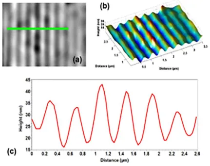
Super-resolution interference microscopy by photonic jet microlens 30
CAD/CAM
N° Authors Article title Page
1
BENALI Farouk
Influence of print parameters on circularity of bores in 3D printed parts38
2
BENCHIHEUB
Slimane
Influence des paramètres de coupe sur la rugosité Ra obtenue lors de l'usinage de l'acier 42CD4
40
3
BOUZIANE
Mohammed-Mokhtar
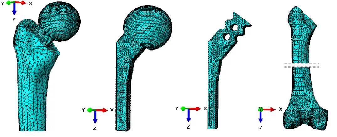
Finite element analysis of fractured hip cement spacers 42
4
HAMMOUDI
Abderazek
Recent Swarm Intelligence Approaches for Mechanical Design Systems
44
5
HARRAG Abdelghani
Multi-objective Optimization of a Cam-Roller Follower Mechanism Based on NSGA-II47 6
OUBOUZID Ahcene
Study and design of an electric wheelchair grimpe stairs 49T.A4
Reliability and condition monitoring
N° Authors Article title Page
1
BOUALI Fakhreddine
Détection des défauts d’engrenages d’une boite de vitesses d’éolienne par SER et SPBF basé sur la DSP du signal52 2
CHITER Ammar
Mise en œuvre de l’algorithme FastICA pour la séparation dessignaux réels de roulements et engrenages
55 3
DRISSI Badreddine
A nonlinear modelling of a spur gear-rolling element bearingsystem with combined faults in nonstationary conditions: simulation
57
4
FEDALA Semchedine
Transmission Error and Support Vector Machines for Gear fault diagnosis59 5
FEDALA Semchedine
Instantaneous angular speed for gearboxes monitoring 616
HABOUSSI Amar
Supervision du système de clinkérisation de la cimenterie par les systèmes Immunitaires artificiels63 7
HAMOUCHE Khalil
Méthode de réduction de dimension des indicateurs de défauts parméta-analyse
65
8
HARROUCHE Fateh
Optimisation Structurelle d’un Système à Inférence Floue FIS (Fuzzy Inference System) pour l’Identification et la Classification des Défauts de Roulements10
MAHGOUN Hafida
Detection of wind turbine faults using instantaneous frequency based on EEMD and STFT ridges73
11
MECHEHOUD
Mohamed Islam
Surveillance en ligne de l’état des outils de coupe par analyse des signaux de force
75
12
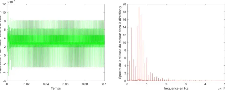
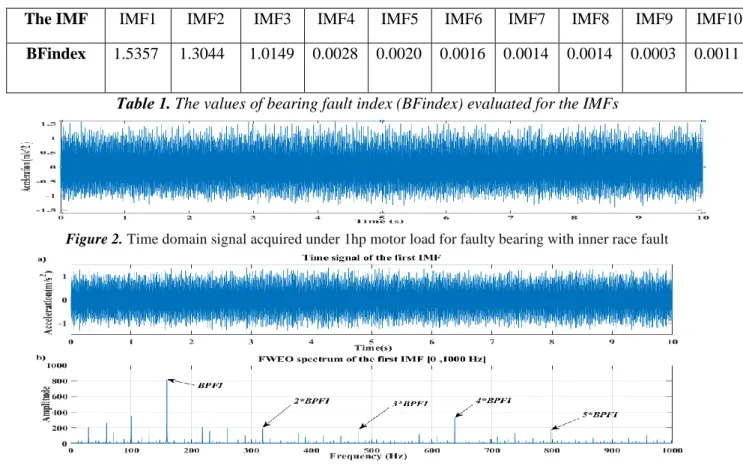
MEZAGHCHA Amine
New Bearing Fault Index (BFindex) for Diagnosis of Rolling Element Bearing77
13
TCHIER Souhir
Cyclostationary indicators analysis of gear faults 79T.B1 Metallic materials for engineering
N° Authors Article title Page
1
BARKAT Mohamed
Redouane
Caractérisation Physico-Chimique D'un Acier Au Carbone Revêtir Par Un Traitements Thermochimique
82
2
BENIDIR Sofiane
Effet de l’ajout d’étain sur les propriétés électrochimiques et spectroscopiques des alliages Zn-Sn84
3
BENSALEM Ilyas
3D Modeling and analysis of metal foams under dynamic loading 854
BOUCHELOUCHE
Fatima
Effet du soudage par friction malaxage similaire sur la microstructure et les propriétés mécaniques d’un joint soudé d’alliage A6003
87
5
DEMOUCHE Mourad
Etude expérimentale du comportement en cisaillement des soudures par friction rotative90 6
FETHI Salah
Application d’une nouvelle théorie hyperbolique de déformation decisaillement pour analyser les plaques FGM sous l’effet des charges thermomécaniques
92
7
HAKIMI Soumaya
Influence de direction de laminage sur le retour élastique lors de lamise en forme des alliages d’aluminium 94
8
MAATI Ahmed
Determination of true Stress-Strain curves From Tensile Tests via three methods97
9
MERTANI Boubekeur
Mohammed Bilel
Etude expérimentale du comportement mécanique des matériaux cellulaire en nid d'abeille soumis à une compression rapide
99
10
REZZIG Djihed
Effects of interphase on elastic properties of aluminum/carbon nanotube nanocomposites100
11
SADOUN Oualid
Prestressing Steel (PS) bars with several surface condition for bond behaviour improvrement of elements in concrete by NSM technique103 12
SAIT Naima
Effect of iodide ions on corrosion inhibition of copper in 0.5 M HCl 1041
BENGHALEM
Mohamed Mustapha
Elaboration et caractérisation des creusets résistants aux hautes températures par coulage en barbotine
106
2
BENMORKAT Nejet
Elaboration of forsterite glass ceramics from medical glass waste 1083
BENNOUIOUA Tahar
Etude du comportement au choc thermique d’un verre revêtu par une couche mince déposée par spray pyrolyse110
4
BOUCHEKRIT Chafia
Synthesis of magnesium oxide from Algerian dolomite 1125
BOUDEGHDEGH
Kamel
Influence of the glass waste on the behavior of the opaque glazes for sanitary ceramic-ware
114
6
BOUNAR
Nedjemeddine
Study of NASICON Ceramics Lithium Ion Conductor LiTi2-x Mox(PO4)3
116
7
BRAHIMI Salim
Preparation and characterization of bioceramic powder from Guelma hydrothermal limestone119
8
CHARGUI Fouzia
Elaboration d’une mullite à partir d’un kaolin d'Algérie par ajout descories d’aluminium 121
9
CHERMAT Zeyneb
Sintering of kaolin carbon mixtures with K2CO3 addition 12310
DJOUALLAH Samira
Phase transformation and sintering behaviour of fluorapatite-alumina composite materials125 11
FRIH Ahmed
The effect of transverse shear on the vibratory behavior of FGMfunctionally graduated plates
127
12
GUERAICHE Larbi
Experimental investigation on E-glass/ epoxy cubic specimens’ length for a constant strain rate in SHPB test131 13
GUERMAT Noubeil
Deposition times influence on properties of 8 wt% Fluorine – dopedTin Oxide thin films deposited by spray pyrolysis
134
14
HOGGAS Khadidja
Superficial mechanical characterization of magnesium aluminate spinel (MgAl2O4) fabricated by Spark Plasma Sintering136 15
KERDJA Leila
Caractérisation et modélisation OOF2 du comportement mécaniquedes revêtements composites
138
16
KERMA El-Yazid
Applied the polarized light backscattering measurements forcharacterizing Alpha Alumina (α-Al2O3) 141
17
KHALDI Mokhtar
À propos de l'influence de la température sur les propriétés19
KHERIFI Djelel
The reaction between alumina and Algerian natural phosphate 14720
LAMARA Smail
The kinetics parameters of cordierite materials synthesized using sol-gel process149
21
LAOUAMRI Hind
Synthesis of anti-reflective silica thin films for optic application 15022
MAROUANI Abdelhak
Effect of the Particles Size on the Optical Transmission Improvement of Eroded Glass152
23
MECHEKEF Houda
Synthèse des mousses de verre à partir de verres de récupération jetés dans la nature155 24
MOKHTARI Afaf
The effect of aluminum powder addition on the sintering ofhydroxyapatite
158
25
NACER Sara
Influence of interphase material parameters on effective material properties of multiphase composites161 26
OSMANI Ismahen
Absorption of silver nanoclusters sodium silicate glass formed byAg/Na ion exchange
163
27
OUBOUZID Ahcene
Numerical study of honeycomb sandwich structures subjected to impact165 28
REDAOUI Djaida
Phase Transformation and kinetic parameters of Mullite FormationPrepared by Sol-Gel Process Using Differential Thermal Analysis (DTA)
167
29
ROUABEH Nouhad
Study of the Structural and Optical properties of the Polyvinyl Chloride polymer (PVC) doped by Cadmium Sulfide with Chemical Method168
30
SOUALEM Azedine
Effet de la température de frittage et du temps de maintien sur ladurée de vie de meule réalisée à partir d’un verre récupéré 171
31
TEKILI Sabiha
Analyse fréquentielle des vibrations des poutres sandwichs à âme viscoélastique et peaux en composites175
32
YOUNES Leila
Effet du temps de traitement de l’échange ionique du verre sur les contraintes résiduelles177
T.B3 Tribology, fracture and fatigue
N° Authors Article title Page
1
AOUNALLAH
Soufyane
Mécanismes d’usure du couple PS Cristal/Acier 100C6 180
Taylor
5
KHENNAFI-BENGHALEM Nafissa
Comportement à l’usure des revêtements en dioxyde de titane et
d’alumine 188
6
KHENNAFI-BENGHALEM Nafissa
Comportement tribologique d’un acier Hss revêtu bipoinçonnant un acier recuit
190
7
MESSAGIER Fatima
Zohra
Frottement du polystyrène cristal glissant sur un acier dur 192
8
OUBOUZID Ahcene
Behavior study of sandwich panels in fatigue by repeated impact 194T.B4 Materials development and applications
N° Authors Article title Page
1
AGGOUN Meriem
Etude de l’effet des paramètres de mise en forme sur lespropriétés mécanique d’un géopolymère à base de Kaolin Tamazert
197
2
AGHILES Bouibed
Preparation and characterization of hybrid materials based on graphene oxide and silica nanoparticles and their effect on the mechanical and thermal properties of epoxy resin composites199
3
AZZEDDINE Hiba
Some mechanical properties of an Mg-RE alloy processed by high-pressure torsion201
4
BELDJEBLI Ouidad
Synthesis and photocatalytic properties of Sol-Gel SnO2 thin films 2035
BENCHIKH Lillia
Preparation of cellulose nanowhiskers (CNC) from "El Diss" plants 2056
BENSEHIL Ilhem
Élaboration et caractérisation de couches minces magnétiques à base du fer207 7
BERARMA Khadidja
Inhibition de la corrosion de l’alliage de l’aluminium 2017A parl’acétate de sodium 209
8
BILLAL Mahdi
Etude des propriétés structurales et physiques d’un matériau hybride(organique-inorganique) à base de poly (alcool vinylique) / gel de silice, synthétisé par la méthode sol-gel211
9
CHERIFI Achraf
Effet de la température sur les déférentes propriétés des nanoparticules de nickel déposé sur l’oxyde d’alumine213
10
DEKHIL Djohra
Elaboration and caracterization of an heterojunction CuO/ZnO prepared by Sol-Gel method12
DERROUICHE Afifa
Effet du laminage à froid sur la microstructure d’un acier inoxydable super-austénitique AISI 904 L220 13
DJOUADA Djahida
Caractérisation des matériaux diélectrique hétérogènes multicoucheen hyperfréquence
222
14
FELLAH Mamoun
Structural characterization of developed near β-Type Titanium Alloys (Ti-25Nb-xZr) for biomedical Applications224 15
FIZI Yazid
Caractérisation et simulation numérique du comportementmécanique de l’Abradable 226
16
GECHI Abla
Thermodynamic properties of the KAg2AsS4 compound, first principles study228 17
GUECHI Abla
Mechanical and anisotropies properties of semiconductorKAg2AsS4
229
18
KATEB Anwar
Study, Application and Modeling of the Acoustic Microwave Signal in Piezoelectric Materials on a Lithium Niobate LiNbO3 Substrate Cut (Y-X)230
19
KEMMACHE Abir
Structural and Optical characterizations of zinc oxide thin films produced via electrochemical method232 20
KHACHEBA Maria
Synthèse et caractérisation structurale et diélectrique de céramiquespérovskites
235
21
KHALIL Seloua
Synthèse et caractérisation structurale d’un composé nanostructuré de Ti, Mo et Zr pour applications biomédicales243
22
MOUHOUBI Sabira
Comportement à la rupture d’un composite stratifié 245 23OURAHMOUN
Abbes Analysis of viscoelastic antiplane contact problemswith long memory
247
24
OURAHMOUN
Abbes Etude variationnelle et numerique d’un probleme de contact de remodelage osseous249 25
TEBBANE Samir
Effect of different types of Kaolin grog on Anorthite phaseformation by reaction with CaCO3
253
T. A1. Modelisation of mechanical systems
T. A2. Metrology in mechanics
T. A3. Computer Aided Design/Manufacturing CAD/CAM
T. A4. Reliability and condition monitoring
Theme B
T. B1. Metallic materials for engineering
T. B2. Glass, ceramics and composites
T. B3. Tribology, fracture and fatigue
A new approach on the Trajectory Planning of the robot for
thermal spray
FARID BETTINE,HALIM MIRABTI,FAROUK LAIDOUDI,FAYÇAL MEDJILI,AMMARHABOUSSI,FATMI HAKIM
UDCMA-CRTI,Research Center in Industrial Technologies CRTI, P.O,Box 64, Cheraga,16014 Algiers, Algeria
Email: [email protected] , [email protected]
Abstract
A new industrial revolution, which its name is the thermal spray by used robot is being spoken today, because the basis of this revolution is industrial robots the most important features of which are accuracy, speed and efficiency. Today in the industrial robot plays a very important role in improving the quality of products. The aim of study was to improve robot trajectories control during the thermal spraying process on complex geometric objects.
In this study, an analysis on the robot kinematics was proposed to find the motion in the end effector. For the solution of this problem, many solutions such as geometric, iterative and algebraic if the joint structure of the manipulator is more complex.
The results show that the proposed approach has not only greatly reduced the computation time but also improved the precision and quality of products.
Key word:Kinematics, thermal spray, trajectories, robot
Results
The technique of robot applications in industry includes the trajectory planning, process simulation, kinematic analysis, robot programming, optimization, coordinates calibration [1,2]. In these steps, the trajectory planning and kinematic optimization are the key points to improve the robot performance and the productivity as well. As a result, the studies concerning the trajectory generation and the kinematic analysis of industry robot are becoming more and more important. In the meantime, due to the advantages of robots, more and more industrial robots have been introduced to the thermal spraying process [3]. Considering the increasing requirement for robot performance and coating quality, the trajectory generation, kinematic analysis and trajectory optimization are becoming hot topics in this field of industry. Therefore, in this study, the aspect of trajectory generation is presented based on the robot’s application in the thermal spraying process.
Figure 1. Operating parameters in the thermal spraying process. [3]
Figure 2. Positions chosen for kinematics analysis. [1]
Références :
[1]Deng, Sihao, et al. "Kinematic optimization of robot trajectories for thermal spray coating
application." Journal of thermal spray technology 23.8 (2014): 1382-1389.
[2] Cai, Zhenhua, et al. "Computer-aided robot trajectory auto-generation strategy in thermal spraying."
Journal of Thermal Spray Technology 24.7 (2015): 1235-1245.
Dynamic modeling of a two stage spur gear system
ELYOUSFI BILAL1,SOUALHI ABDNOUR2,MEDJAHER KAMAL3,GUILLET FRANÇOIS4,ELBADAOUI MOHAMED5
1,2,4,5Laboratoire Analyse des Signaux & des Processus Industriels, Université Jean Monnet de Saint Etienne 3 Laboratoire génie de production, Ecole Nationale d’Ingénieurs de Tarbes
Email : [email protected]
Abstract
Nowadays, geared systems are widely used in industrial applications such as automobiles, wind turbines, airplanes and other rotary machines. Gears generally undergo high service load, harsh operating conditions and inevitable fatigue [1]; this is why maintainers consider them as a critical component. Therefore, early fault detection and diagnosis of gears leads to operational and maintenance cost reductions and ensure people safety; spur gear dynamic model can help to understand faults generation mechanism and to develop an effective faults detection and diagnosis methods. Models proposed in the literature can be gathered into three categories according to the method used for time varying mesh stiffness (TVMS) evaluation: analytical methods [2], finite element methods [3] and experimental methods [4]. Another classification of these models can be done following the number of parameters considered in the study like shafts torsional deformation and bearings stiffness and damping. In this study, the potential energy method proposed by Yang and Lin [5], is used to compute the TVMS of the gear pairs considering the hertzian component, bending component, shear component, axial compressive component and torsional component of the gear body, a 10 DOF model is developed to describe the dynamic behavior of a two stage gearbox including the bearing and the shafts stiffness. MATLAB Ode solvers are used for the resolution of the differential equation system to estimate the different quantities such as vibration and velocity in both healthy and faulty conditions.
Key word: gear modeling, potential energy method, diagnostics, time varying mesh stiffness.
Results
Figure 1a, 1b, 1c, 1d represent the TVMS evolution despite the first shaft angle, 1a represents the healthy gear stiffness, 1b represents the deformation of the meshing stiffness with different crack sizes, 1c represents the deformation resulting of a spall in the tooth tip and 1d represent the case of a broken tooth. The dashed line refers to the healthy TVMS in each case.
Figure 1: Stiffness vs. angular displacement 𝜃1of perfect gears (a); cracked gears (b); spalled gears (c) and gears with broken tooth (d). 0 10 20 30 40 50 4.5 5 5.5 6 6.5 7 7.5 8 8.5x 10 8 angle (°) st iff nes s (N /m ) (a) (d) (c) (b)
Table1 specifies the different parameters used for the simulation of the dynamic model.
Table 1: simulation parameters
Figure 2a, 2b, 2c, 2d represent respectively the linear acceleration of the first pinion in healthy conditions, cracked gear, spalled gear and a gear with a broken tooth. One can detect the two meshing periods 𝑇1 = 0.0021𝑠 of the first stage and 𝑇2 = 0.0028𝑠 of the second stage; a crack or a spall cause a local amplification of the vibration at the fault position, the case of a broken tooth is drawn in two revolutions to show the high level of vibration it causes.
Figure 2: vibration 𝑦1 of perfect gears (a); crack ed gears (b); spalled gears (c) and gears with brok en tooth (d).
References:
[1] Liang, Xihui, Ming J. Zuo, and Zhipeng Feng. "Dynamic modeling of gearbox faults: A review." Mechanical Systems and Signal Processing 98 (2018): 852-876.
[2] J Chaari, Fakher, Tahar Fakhfakh, and Mohamed Haddar. "Analytical modelling of spur gear tooth crack and influence on gearmesh stiffness." European Journal of Mechanics-A/Solids 28.3 (2009): 461-468.
[3] V.K. Ambarisha, R.G. Parker, Nonlinear dynamics of planetary gears using analytical and finite element models, J. Sound Vib. 302 (3) (2007): 577–595.
[4] N.K. Raghuwanshi, A. Parey, Mesh stiffness measurement of cracked spur gear by photoelasticity technique, Measurement 73 (2015): 439–452.
[5] Yang, D. C. H., and J. Y. Lin. "Hertzian damping, tooth friction and bending elasticity in gear impact dynamics." Journal of mechanisms, transmissions, and automation in design 109.2 (1987): 189-196.
0.042 0.043 0.044 0.045 0.046 0.047 0.048 -400 -300 -200 -100 0 100 200 300 400 Time (s) A cce le ra tio n y1 ( m /s2 ) T1 = 2.1ms T2 = 2.8ms 0.042 0.043 0.044 0.045 0.046 0.047 0.048 -600 -400 -200 0 200 400 600 Time (s) A cce le ra tio n y1 ( m /s2 ) 0.042 0.043 0.044 0.045 0.046 0.047 0.048 -400 -300 -200 -100 0 100 200 300 400 Time (s) A cce le ra ti o n y1 ( m /s2 ) 0 0.01 0.02 0.03 0.04 0.05 0.06 0.07 0.08 -1 -0.5 0 0.5 1 1.5 2x 10 5 Time (s) A cce le ra tio n y1 ( m /s2 )
Material
Steel: 𝐸
= 2.068 × 10¹¹ 𝑃𝑎; 𝑣 = 0.3Modulus
𝑚1= 𝑚2= 2Teeth numbers
𝑍1= 19 𝑒𝑡 𝑍2= 25, 𝑍3= 19 𝑒𝑡 𝑍4= 25Pressure angle
𝛼 = 20𝑜Input frequency
𝐹1 = 25 𝐻𝑧 (a) (d) (c) (b) Brok en tooth crack ed tooth spalled toothOptimalsynthesis of a disc cam mechanism with translating flat‐face follower using
various follower motionlaws
FERHAT HAMZA1,DJEDDOU FERHAT1,HAMMOUDI ABDERAZEK1,REZKI INES1
1Applied Precision Mechanics Laboratory,Institute of Optics and Precision Mechanics, University of Setif 1
Email :[email protected]
Abstract
Cam-follower is one of the important and versatile mechanisms existing in mechanical machinery when the task of accurate function is required. The mechanism consists of transforming the rotary motion of the cam to a translating or oscillating motion of the follower having predetermined kinematic characteristics with a high level of precision. Applications of cam mechanism are widely found in mechanical devices and machines such as printing presses, shoe machinery, textile machinery, screw machines, etc. Once the cam curve is decided, the practical cam profile can be easily designed based on the basic size of the mechanism and the types of cam and follower. Because the property of the cam curve directly affects the performance of the cam mechanism, how to design the cam curve with more advantageous efficiency with respect to the design requirement is a challenging task for mechanical engineer [1].
The motion design, which deals with selecting the suitable law to describe the follower motion, plays a key role in the cam design process.The purpose of the present paper is to optimize the design of a cam mechanism with translating flat-face followerregarding several follower motion laws.The motion laws considered in this study are cycloidal, modified sinusoidal acceleration, polynomial 3-4-5, and polynomial 4-5-6-7 functions [2,3].The proposed optimization procedure aims to optimize the size of the system andis based on satisfying multiple constraints as cam pressure angle, curvature radius and several geometric constraints.The design parameters, aimed to be optimized, include the base circle radius of the cam Rb,length of the follower face L as shown in Fig.1.
Keywords: cam mechanism, flat faced follower, optimization, follower motion law
b C e x y b R L
Fig. 1 Cam mechanism with translating flat‐face follower
Results
The proposed methodology is applied to optimize the cam mechanism design parameters where the follower offset is set equal to zero (e=0 mm). The optimization problem is solved by employing the well-known fmincon optimization tool. The motion kinematics of the four laws are illustrated during the rise period in Figs. 2 to 5. The final optimization results aretabulated in Table 1.
Fig. 2 Follower displacement for different motion laws Fig. 3 Follower velocity for different motion laws
Fig. 4 Follower acceleration for different motion laws Fig. 5 Follower jerk for different motion laws
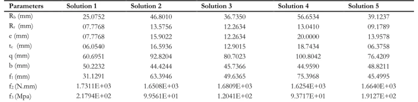
Table 1. Optimal design parameters of the cam mechanism with different motion laws of the follower
Motion law Objective function Rb (mm) L (mm)
Modified sine 62.4064 35.5340 26.8725
3-4-5 Polynomial 66.3508 37.7029 28.6479
Cycloidal 72.1398 41.5821 30.5577
4-5-6-7 Polynomial 83.2029 49.7804 33.4225
Références :
[1] Q. Hua, L. Chang-Jun, L. Zi-Ye, O. Hiroaki, W. Jian, Y. Yong, A universal optimal approach to cam
curve design and its applications. Mech Mach Theory 40: 669–692 (2005).
[2]RL. Norton, Cam Design and Manufacturing Handbook.Industrial Press, New York (2002).
[3] HA. Rothbart, Cam design handbook. McGraw-Hill, New Jersey (2004).
A study of hydrodynamic lubrication in a circular journal bearing.
ABDELKADER GHALEM1, MILOUD TAHARABASE2,ABDELKADER SAHLI3
1Labo de LME,Faculté de SEI, Université Hassiba Benbouali of Chlef, Algeria 2Labode LME, Faculté de Technologie, Université Hassiba Benbouali of Chlef, Algeria 3Labo de LME, Faculté de Technologie, Université Hassiba Benbouali of Chlef, Algeria
Email :[email protected]
Abstract
A study of hydrodynamic lubricationof a fluid film in a circular journal bearing is presented in this paper. In bearing analysis, oil film is routinely assumed to be isothermal. The modelling, based on the numerically Resolution of the Reynolds equation, makes it possible to determine the evolution of the hydrodynamic performances of the bearing.A finite difference computer program was developed to numerically solve the Reynolds to find the trend of a few variables of a sliding bearing such as the minimum thickness of the film, the eccentricity ratio, the journal speed and the maximum pressure in the contact. The pressure field in the lubricant film was calculated in both the circumferential and axial directions.This numerical study is carried out thanks to the development of a hydrodynamic calculation program using the Fortran 90 language. Such simple boundary conditions result in significant computational savings and, therefore, may be attractive to the practicing designer.In comparison with the published results, generally these results showed better agreement.The results show that the variations of the minimum thickness of the film and the eccentricity ratio have a considerable influence on the operating performance of a bearing.
Keywords:Circular journal bearing, Hydrodynamic lubrication, Finite Difference Method, Fortran 90.
Geometric model.
Figure 1. Schematic representation of a circular journal bearing.
Results
From the pressure versus circumferential co-ordinates graphs one can say that maximum pressure obtained where oil film thickness is minimum and zero pressure in cavitations zone.
Figure. 2.Rrepresented the repartition of film thickness in radial and circumferential directions. hmin = R.x e O1 O2 z L D
Fig 2. Repartition of film thicknessin radial and circumferential directions.(W=7000N, V=3000Tr/mn)
Figure. 3. Illustrates the circumferential pressure distribution against angular position.
Fig 3. Pressure distribution in radial and circumferential directions.(W=7000N, V=3000Tr/mn)
Références
:
[1] Fillon, M., and Bouyer, J. 2004. Thermohydrodynamic analysis of a worn plainjournal bearing.
Tribology International. Vol. 37(2004), pp. 129-136.
[2] J. L. LIGIER,(1997), ‘Lubrification des paliers moteurs’, Editions Technip, Paris.
[3]K D. Chaitanya and Dilip C Patel ,(2005), ‘‘ experimental analysis of pressure distribution of
hydrodynamic journal bearing: a parametric study’’ International Conference on Mechanical
Engineering 2005, Dhaka, Bangladesh.
[4]Z. Yaacob and M. Bin Hasan ,(2014), ‘‘ experimental Family of Gauss-Seidel Method for Solving 2D
Reynolds Equation in Hydrodynamic Lubrication Problem’’ Conference of (IRICT), (2014) 361-369.
Johor, Malaysia.
[5] J. Frêne, D. Nicolas, B. Degueurce, D.Berthe, M. Godet, Lubrification hydrodynamique paliers
etbutées, Eyrolle, Paris, (1990).
0 20 40 60 80 100 120 140 160 180 200 0 50 100 150 200 250 300 350 400
Disatnce from meniscus (mm)
T h ic k n e s s o f s o li d s k in (m m ) Vc1= 0.8 m/min Vc2= 1 m/min Vc3= 1.13 m/min 0 100 200 300 400 500 600 700 0 20 40 60 80 100 120 140 160 180
Disatnce from meniscus (mm)
D e n s it y o f h e a t fl u x (W / c m 2 ) Vc2 = 1 m/min Vc1 = 0.8 m/min Vc3 = 1.13 m/min
Heat transfer in the mold of continuous casting
KATIB HAMLAOUI1, 2,HOCINE BENDJAMA1, KHEIREDDINE SLIMANI1,LOUAFI SNANI2
1Research Center in Industrial Technologies CRTI, B.P.64, Cheraga 16014 Algiers, Algeria, 2Badji Mokhtar University -Annaba- B.P.12, Annaba, 23000 Algeria,
Email :[email protected]
Abstract :
Continuous casting of slabs is a widespread steelmaking process. It occupies an important place in the production chain because of the advantages over the traditional ingot casting technique, such as: energy saving, labor, better performance and product quality. The trend of research today is oriented towards a generalized modeling of the process [1]
The main function of the mold is to form a solid crust of sufficient thickness to eliminate the risk of breakout; it is also important that the crust thus formed does not give rise to surface or subcutaneous defects. The most important parameters of mold solidification are heat transfer, oscillation and lubrication [2].
This thickness increases with the value of the viscosity at 1500 ° C of the slag and with a speed of extraction. When the starting crystallization temperature is high (> 1100 ° C), thickening of the slag film can occur at the bottom of the mold.
As long as a liquid slag film is present in contact with the steel, the hydrodynamic friction forces remain quite low. Problems can arise when this liquid film is no longer present: a solid-solid friction can then occur. The lubricant used in the mold can have a significant influence on thermal extraction. [3].
Keyword:Continuous casting, mold, lubricant, heat transfer.
Results
100 200 300 400 500 600 700 800 900 1000 0 10 20 30 40 50 60 Temperature (c°) V is c o s it yCrystallization of powder from the casting:
Physical properties of continuous casting :
[4]
Characteristic Data
Density ρ in the liquid state (g/cm3) 7 Tf melting temperature (°C) 1536,6 Temperature of the casting (°C) 1520
Speed of the casting (m/min) 0.8, 1 and 1.13
Extraction speed (m/min.) 1,5
Depth of meniscus (mm) 200
Référence :
[1].LoïcBazart,"Operation Mode Change Detection: Application to the continuous flow of
steel","IAEM Lorraine doctoral school", PP 95, 2014.
[2].R. Alberny and A. Leclercq, "the mold of continuous slab casting and its thermal balance
(metallurgy magazine)” PP 547, July-August 1976.
[3]. B. Mazumder,” A Process fo Developing Continuous Casting mold-powder(Regional Research
Laboratory, Bhubaneswar, India)” PP 774,July 1999
[4]. Jeanne Choné, "Continuous Casting of Steel (Physical and Metallurgical Data)", "Engineering Techniques", No.: M 7 810. PP 5-8, 2005.
Modélisation d’un robot manipulateur de type SCARA application au fraisage
BILLEL LOUNICI1,MOHAMMED OUALI2,EL HADI OSMANI3
1 2 3Laboratoire de Structure, Faculté de Technologie, Université Saad Dahlab de Blida
Email : [email protected]
Résumé
Le fraisage est un procédé de fabrication mécanique par enlèvement de matière, assuré par deux mouvements : de coupe (rotation de la fraise) et d’avance (translation de la pièce). Ce procédé a des avantages tel que : un rendement élevé, surface bien fini, une haute précision...
On propose de modéliser un robot manipulateur de type SCARA à trois degrés de liberté à chaîne ouverte, porte les deux mouvements : de coupe et d’avance en même temps. La solution proposée, nous semble la plus appropriée et la plus judicieuse par rapport à l’utilisation des machinescartésienne, généralement, utilisées pour le fraisage. Les objectifs visés lors de cette modélisation : qualité supérieure, rapidité avec une grande flexibilité pour des formes compliquées, l’espace de travail, la mobilité et l’agilité du modèle proposé.
L’intérêt de notre travail consiste à établir une étude cinématique et dynamique du bras mécanique articulé, d’établir, en premier lieu, plusieurs modèles, à savoir les modèles géométriques (MGD/MGI), les modèles cinématiques (MCD/MCI), et le modèle dynamique (MDI) nécessaires pour l’étude, et, en deuxième lieu, d’utiliser le logiciel MATLAB pour l’établissement du modèle numérique.
Mots clés : Manipulateur de type SCARA, Fraisage, Modélisation, Matlab
Figure.1 Chaine cinématique de solution proposée Figure.2 Modèle CAO de la solution proposée
Résultats
Tableau 1. Paramètres géométriques du robot
j 𝜎𝑗 𝛼𝑗(𝑟𝑎𝑑) 𝑑𝑗(𝑚) 𝑞𝑗(𝑟𝑎𝑑) 𝑟𝑗(𝑚)
1 1 0 0 0 𝑅1
2 0 0 𝐷1=0.1875 𝑞1 0
3 0 0 𝐷2=0.25 𝑞2 0
Pour suivre la description morphologique (mouvement articulaire) du robot lors de l’exécution de la tâche de façon systématique, exige une méthode de modélisation adéquate pour assure un bon suivi. La méthode de Denavite-Hartenberg [1] est la plus répondus pour notre robot. Cette dernière permit nous de remplir le tableau 1.
La programmation, sous MATLAB, permet d’obtenir les résultats de la modélisation précédente sous forme graphique afin de faciliter la compréhension de l’évolution des variables articulaires, telle que : 𝑞𝑗, 𝑞̇𝑗, 𝑞̈𝑗, 𝑘𝑗
au cours de durée de la tâche.
Figure.3 Déplacements articulaires du robot
Figure.4 Vitesses articulaires du robot
Figure.5 Accélérations articulaires du robot Figure.6 Couples articulaires du robot
Références
:
[1] Denavite J. Hartenberg R.S, A kinematic notation for lower pair mechanism based on matrices, Trans.
Of ASME, J. of Applied Mechanics, Vol. 22, juin 1955, p. 215-221.
[2]
Khalil W. Dombre E, Modélisation identification et commande des robots. Hermes science, Paris, 1999.[3]
Paul R.C.P, Robot manipulators: mathematics, programming and control, MIT press, Cambridge, 1981.[4]
Angeles J, Fundamentals of Robotic Mechanical Systems (Theory, Methods, and Algorithms) Springer,2014.
[5]
Osmani E.H, Dynamique Des Systèmes Multicorps Appliquée aux Bras Manipulateurs, mémoire de magister, université Saad Dahlab de Blida, Faculté de technologie, Département de mécanique. Algérie, 2012.[6]
Luh J.Y.S, Walker M.W, Paul R.P.C, On line computational schema for mechanicals manipulators, Journal of dynamics systems, measurement and control, V. 102, 1980.Modélisation numérique du transport éolien par la méthode des éléments
discrets
HOUSSEMSELMANI1
1LMPA, Institut d’optique et mécanique de précision, Université de Ferhat Abbas Sétif 1
Email :[email protected]
Résumé :
La méthode des éléments discrets (DEM) introduite par [1], est parmi les outils les plus puissants pour la simulation des matériaux granulaires. La DEM est basée sur une approche Lagrangienne qui détermine la position, la vitesse et l'orientation des particules à chaque pas du temps durant la simulation. Cette méthode est capable de simuler l'écoulement des grains de propriétés physiques différentes.
De même que pour un assemblage de particules, les forces de contact sont dérivées d'une loi de contact définie (modélisée par un système de ressort / amortisseur), fonction des paramètres du matériau, des interpénétrations des particules et des vitesses relatives. En limitant l'effet des interactions aux seules particules voisines, l'équation du mouvement de Newton peut être résolue explicitement pour chaque particule à chaque pas de temps. L'interpénétration peut être considérée comme la déformation des particules locales au contact, mais est principalement un artifice destiné à expliquer et à simplifier la résolution numérique. Dans ce travail, l'approche par dynamique moléculaire est utilisée et le mot DEM qui sera utilisé pour désigner cette approche particulière couplée avec un modèle RANS pour la phase fluide. La figure (1) montre le résultat de la simulation de 1000 particules.
Key word: Modélisation numérique, éléments discrets, flux de masse saturé.
Résultats :
Le transport de sable stable et homogène est essentiellement quantifié par le flux saturé volumétrique Qsat,
c'est-à-dire le volume des particules traversant une surface verticale par unité de temps. Il a la dimension d'une longueur au carré par unité de temps. La question clé est la dépendance de Qsat avec la vitesse de
cisaillement ou, de manière équivalente, sur le nombre de Shields Sh. Afin de mettre en évidence cette dépendance, la figure (2) montre le flux saturé redimensionné en fonction du nombre de Shields. Les résultats obtenus sont en bon accord avec les observations expérimentales, nous avons aussi trouvé que le flux saturé a une dépendance linéaire avec le nombre de Shields (ou u2
*) dans le cas du transport éolien par saltation. La
plupart des modèles de transport éolien négligent l'influence de la rétroaction négative du transport sur le flux. Par conséquent, ils ne donnent pas la mise à l'échelle correcte, ce qui prédit Qsat / u3*
La figure (2) révèle l'existence d'un seuil de vitesse de cisaillement en dessous duquel le flux s'annule. Plus précisément, nous définissons un nombre de Shields dynamique Shd de l'extrapolation de la courbe de flux
saturé à 0, ce qui donne dans notre cas Shd = 0.004 pour l'air (ρp / ρf =2000) où ρp est la masse volumique du
Figure 1. Photo instantanée de la simulation avec un profil de vent initialement logarithmique. Le système contient 1040 particules, le nombre de Shields Sh = 0.02. Les couleurs représentent la vitesse des particules.
Figure 2.Flux de masse normalisé en fonction du nombre de Shields obtenu avec la simulation numérique et comparé avec les résultats numérique de [2].
Références :
[1] Cundall, P. A., and O. D. L. Strack (1979), A discrete numerical model for granular assemblies,
Géotechnique, 29, 47-65.
[2] Durán, O., B. Andreotti, and P. Claudin (2012), Numerical simulation of turbulent sediment
transport, from bed load to saltation, Physics of Fluids, 24, 103,306.
A New Hybrid Swarm Intelligence Algorithm for Engineering
Applications
SELMANIHOUSSEM1,HAMMOUDI ABDERAZEK1,*
1Applied Precision Mechanics Laboratory, Institute of Optics and Precision Mechanics, University of Setif 1 *Email: [email protected]
Abstract
The search for the best compromise between economic, mechanical and technological imperatives has always been the primary aim of the mechanical engineer. Most design optimization problems in structural engineering are highly non-linear, include several constraints on stresses, displacements, load carrying capability, and geometrical configuration. Up to now, various optimization algorithms have been developed and introduced to solve engineering optimization problems. These methods can be divided into two major categories, i.e., gradient-based methods and meta-heuristic algorithms. Usually, the gradient algorithms are sensitive to initial values and need the derivatives information of the objective and constraints functions, so it can be as an available option for solving the simple problems while they generally fail to solve real engineering design problems. By contrast, metaheuristic optimizers do not require the gradient information of the optimization problem and use random steps in order to achieve the global or near-global solution.
During the last few decades, the researchers have been developed and proposed various algorithms to solve the variety of real-life engineering optimization problems. In the same context, this paper presents an effective hybrid algorithm based on swarm intelligence approach and gradient-based algorithm for solving complex engineering optimization problems. The performance of the proposed algorithm is numerically tested using seven problems including four unconstrained benchmark functions and three real challenging mechanical problems. The optimization results obtained by the developed variant are compared with those of the literature using different algorithms. The comparisons results illustrate that the proposed method has fast convergence speed and is more successful for most test problems in terms of solution quality and computational efficiency.
Keywords: Meta-heuristics, Swarm intelligence algorithms, Engineering design optimization.
Results
In the first step, the performance of the developed algorithm is tested by optimizing four mathematical functions (F1-F4) collected from the special session CEC 2005 and three mechanical problems. For the functions, our algorithm method is compared with following four implemented optimizers: particle swarm optimization (PSO), grey wolf optimizer (GWO), ant lion optimizer (ALO), sine cosine algorithm (CSA) and whale optimization algorithm (WOA). For faire comparison between the investigated techniques, the population size and the maximum iterations are fixed as: 𝑛𝑝 = 50, 𝑡𝑚𝑎𝑥 = 300.
The performances of the meta-heuristics in solving the problem are evaluated in terms of convergence speed, solution quality and robustness. The algorithms are executed 50 times and the statistical results include the best, mean and the worst solutions as well as standard deviation.
Fig. 1 The 2-D version of the mathematical functions
Fig. 2 Convergence curves of the proposed method and other algorithms for mathematical functions
Barrier F R RB RM bM d M M C F t ri r0
Fig. 3 Schematic view of the mechanical problems Table 1 Results of the developed algorithm for the benchmark test functions.
Function 𝒇(𝒙∗) Accuracy level Stat. WOA SCA ALO PSO GWO New hybrid
algorithm
F1 0 1.00E-06 Mean 8.22E-46 1.20E+02 4.90E+00 9.06E-03 3.38E-16 2.52E-252
SD 2.67E-45 1.69E+02 1.40E+01 1.05E-02 3.15E-16 0.00E+00
SR 100 0 0 0 100 100 Rank 2 6 5 4 3 1
F2 0 1.00E-06 Mean 3.92E-31 2.55E-01 5.39E+01 2.06E-01 3.67E-10 1.48E-122
SD 1.31E-30 2.23E-01 4.59E+01 9.95E-02 2.45E-10 8.14E-122
SR 100 0 0 0 100 100 Rank 2 5 6 4 3 1
F3 0 1.00E-06 Mean 5.65E+04 1.37E+04 6.78E+03 1.84E+02 5.66E-02 2.66E-224
SD 1.61E+04 9.07E+03 3.24E+03 6.89E+01 1.78E-01 0.00E+00
SR 0 0 0 0 0 100 Rank 6 5 4 3 2 1
F4 0 1.00E-06 Mean 5.34E+01 4.14E+01 2.00E+01 1.65E+00 5.53E-04 1.047E-121
SD 2.97E+01 1.18E+01 4.43E+00 2.77E-01 4.40E-04 5.566E-121
SR 0 0 0 0 0 100 Rank 6 5 4 3 2 1
References:
[1] Abderazek, H., Ferhat, D., & Ivana, A. (2017). Adaptive mixed differential evolution algorithm for bi-objective tooth profile spur gear optimization. The International Journal of Advanced Manufacturing Technology, 90(5-8), 2063-2073. [2] Yildiz, A. R., Abderazek, H., & Mirjalili, S. A Comparative Study of Recent Non-traditional Methods for Mechanical Design Optimization. Archives of Computational Methods in Engineering, 1-18.
NUMERICAL STUDY OF MIXED CONVECTION WITH ENTROPY
GENERATION IN A SQUARE CAVITY FILLED WITH HYBRID
NANOFLUIDS.
ILHEMZEGHBID1,RACHIDBESSAIH2
1
Institute of Science and Technology, Department of Science and Techniques, University Center Abdel Hafid Boussouf, Mila, 43000, Algeria
2
LEAP Laboratory, Department of Mechanical Engineering, University of Frères Mentouri- Constantine, Ain El. Bey road, Constantine, 25000, Algeria.
Email :[email protected]
Abstract
Hybrid nanofluids are new nanotechnology fluids that are synthesized by dispersing two different nanoparticles in a conventional heat transfer fluid. The effects of hybrid nanofluids on the flow of mixed convection and entropy generation in a square cavity with a movable upper wall are discussed in this paper. The finite volume method was used in the numerical scheme with the SIMPLE algorithm. The numerical results show that increasing the Richardson number increases the rate of heat transfer, while the incorporation of hybrid nanofluids into the base fluid greatly minimizes the entropy generation within the cavity.
Key word: Hybrid Nanofluid, Entropy Generation, Mixed Convection.
Results
In order to study the mixed convection in a square cavity provided with an active upper wall filled with a Al2O3-Cu / water hybrid nanofluid with (Al2O3 = Cu = 0.02), simulations were performed for Ri = 0.1 to 20
and Re = 10 to 200, to see the effect of Richardson and Reynolds numbers on the structure of flow and heat transfer. We can see in figure1 a single cell flow of elliptic form; this is to explain by the fluid trajectory. In addition, forced convection mode (low Ri values), external forces are dominant. The increase in the number of Richardson leads to the transition from convection mode to mixed convection mode. A further increase in Ri causes the convection mode to change to natural convection mode and the main flow is concentrated in the vicinity of the active wall of the cavity. The shearing effect will lead to the formation of the cell becoming increasingly distended with increasing Richardson number.
Figure 2 illustrate the profile of Nuavg, St and Be for different values of the volume fraction of nanoparticles
for alumina (Al2O3) and copper (Cu) for different values of Ri, it is found that the increase in causes an
increase in Nuavg, while St and Be tend to decrease as increases, and this performance of Nuavg is due to the
improved thermal conductivity of the hybrid nanofluid. Also the increase in Richardson's number leads to a growth of the heat transfer rate, while the entropy generation and the Bejan number are minimized.
Figure 2 show that the increasing incorporation of the hybrid nanoparticle increases the number of Nusselt on the one hand and on the other hand reduces the irreversibility of the flow and the number of Bejan. So the simulation results revealed that the heat transfer performance increases due to the acceleration of the flow. The presence of hybrid nanoparticles in a base fluid has resulted in a considerable increase in heat transfer.
FIGURE 1. Streamlines for Al2O3-Cu / water hybrid nanofluid filled cavity with the variation of Ri and Re = 100, Al2O3=Cu=0.02.
FIGURE 2. Effect of Richardson number on Nuavg, St and Be with different nanoparticule volume fraction.
References:
[1] J. A. Ranga Babu, K. Kiran Kumar and S. Srinivasa Rao, State-of-art review on hybrid nanofluids,
Renewable and Sustainable Energy Reviews, vol. 77, pp. 551-565 (2017).
[2] M. Benkhedda, T. Boufendi and S. Touahri, Laminar mixed convection heat transfer enhancement
by using Ag-TiO2-water hybrid nanofluid in heated horizontal annulus, Heat and Mass Transfer
(2018).
[3] A. Karimi and M. Afrand, Numerical study on thermal performance of an air-cooled heat
exchanger: Effect of hybrid nanofluid, pipe arrangement and cross section, Energy Conversion and
Management, vol. 164, pp. 615-628 (2018).
[4] C. J. Ho, J. B. Huang, P. S. Tsai and Y. M. Yang, Preparation and properties of hybrid water-based
suspension of Al2O3 nanoparticles and MEPCM particles as functional forced convection fluid,
International Communications in Heat and Mass Transfer, vol. 37, pp. 490-494 (2010).
[5] Sahoo, R. Rashimi and J. Sarkar, Heat transfer performance characteristics of hybrid nanofluids as
coolant in louvered fin automotive radiator, Heat Mass Transfer, vol. 53.pp. 1923-1931 (2017).
[6] S. Suresh, K. P. Venkitaraj, P. Selvakumar and M. Chandrasekar, Effect of Al
2O
3-Cu/water hybrid
nanofluid in heat transfer, Experimental Thermal and Fluid Science, vol. 38, pp. 54-60(2012).
[7] M. A. Mansour, S. Siddiqa, R. S. R. Gorla and A. M. Rashad, Effects of heat source and sink on
entropy generation and MHD natural convection of a Al
2O
3-Cu/water hybrid nanofluid filled with
square porous cavity, Thermal Science and Engineering Progress(2017).
[8] S. V. Patankar, Numerical heat transfer and fluid Flow, Hemisphere, Washington, DC (1980).
G e o m e tr y 1 0 0.2 0.4 0.6 0.8 1 0 0.2 0.4 0.6 0.8 1 G e o m e tr y 1 0 0.2 0.4 0.6 0.8 1 0 0.2 0.4 0.6 0.8 1 G e o m e tr y 1 0 0.2 0.4 0.6 0.8 1 0 0.2 0.4 0.6 0.8 1 = N u 0.01 0.015 0.02 0.025 0.03 0.035 0.04 12 12.5 13 13.5 14 14.5 15 15.5 16 16.5 17 Ri=0.01 Ri=0.1 Ri=1 Ri=10 Ri=20 a v g Al O2 3 Cu Geometry 1 Re=100 = S t 0.01 0.015 0.02 0.025 0.03 0.035 0.04 0.028 0.03 0.032 0.034 0.036 0.038 0.04 Ri=0.01 Ri=0.1 Ri=1 Ri=10 Ri=20 Geometry 1 Re=100 Al O2 3 Cu = B e 0.01 0.015 0.02 0.025 0.03 0.035 0.04 0.88 0.89 0.9 0.91 0.92 0.93 Ri=0.01 Ri=0.1 Ri=1 Ri=10 Ri=20 Al O2 3 Cu Geometry 1 Re=100
Effet des tolérances sur la performance cinématique d’un mécanisme plan
Noufel Belkadi 1, Ferhat Djeddou1,Lakhdar Smata1
1Université Ferhat Abbas, Institut d’optique et de Mécanique de Précision, Sétif, Algerie
Email : [email protected]
Résumé
L’objectif de ce travail est de déterminer les erreurs de position, de vitesse et d’accélération dues aux tolérances de fabrication, par l’utilisation de la méthode de linéarisation directe. L’étude se compose de deux parties. La première partie, analyse des tolérances, consiste à la détermination de l’erreur des paramètres cinématiques d’un mécanisme bielle-manivelle dues aux tolérances de fabrication de chaque élément. La deuxième partie, optimisation des tolérances du mécanisme, concentre sur la minimisation des tolérances en utilisant le cout de fabrication comme fonction objectif pour réduire les erreurs cinématique du coulisseau. L’analyse de tolérance permet de réaliser un produit fonctionnel avec un coût optimal. Mots clés: Analyse de tolérance, Optimisation, Mécanisme bielle-manivelle.
1. Introduction
Le système bielle-manivelle est un système mécanique qui tire son nom des deux pièces mécaniques qui le caractérisent : la bielle et la manivelle. Ce dispositif réalise la transformation du mouvement linéaire alternatif de l'extrémité de la bielle en un mouvement de rotation continu disponible sur la manivelle
(vilebrequin), et vice-versa. Sa cinématique, apparemment simple, cache une fonctionnalité technologique de première importance utilisée très couramment dans de nombreux mécanismes : moteur, pompe, scie,
barrière automatique, etc.
Dans ce travail une analyse de tolérance d’un mécanisme bielle-manivelle à coulisseau excentrique est effectuée. La première partie de cette étude est consacré à déterminer l’effet des tolérances de fabrication sur la performance cinématique de ce mécanisme, en utilisant la méthode de linéarisation directe comme approche générale et systématique pour quantifier les erreurs cinématiques.
La deuxième partie, optimisation des tolérances du mécanisme, consacrée à la minimisation des tolérances pour réduire les erreurs cinématiques de mouvement de sortie du coulisseau. Pour cela, en utilisant une fonction objectif qui exprime le cout de fabrication en fonction des tolérances des éléments du mécanisme.
Figure 1. Schéma d’un mécanisme bielle-manivelle à coulisseau excentrique [2].
2. Résultats de l’analyse de tolérance
Un mécanisme de manivelle-coulisseau élémentaire est utilisé ici pour montrer l'influence des tolérances de fabrication sur la performance cinématique d’un mécanisme plan.
2.1. Détermination de l’erreur de position, de vitesse et d’accélération
3. Modèle d'optimisation:
L’optimisation de la synthèse de la tolérance de la bielle-manivelle à coulisseau est utilisée pour assurer la précision de sortie requise au coût de fabrication le plus bas.
( )
( )
( )
1 1 2 2 3 3
Min C=min G l +G l +G b
Soumis à: 1 g = 1.96
3.1. Présentation des résultats d’optimisation
Références
:
[1] P. Flores, “A Methodology for Quantifying the Kinematic Position Errors due to Manufacturing
and Assembly Tolerances, ” Journal of Mechanical Engineering, vol.576, pp. 457–467, 2011.
[2] A. Fogarasy, “ The influence of manufacturing tolerances on the kinematic performance of
mechanisms,” Proc Instn Mech Engrs, vol. 212, pp. 35–47, 1997.
[3] Z. Dong, “New Production Cost-Tolerance Models for Tolerance Synthesis,” Journal of
Engineering for Industry, vol. 116, pp. 199–206, 1994.
Solution initiale Solution optimale
δl1 0.05 0.0364590
δl2 0.07 0.0380532
δb3 0.04 0.0278652
Facteur de confiance γ 0.5936 1.9612
Etudeanalytique et numérique du comportement
thermoelastique de filaments doublement spiralés
Nacera BENGHANEM(*);.Abdelhamid BECHEUR(**)
(*) Laboratoire de Physique ThéoriqueLPT, Faculté des Sciences Exactes,Université de Bejaia, 06000 Bejaia, Algérie Auteur correspondant : email : [email protected]
(**)Laboratoire de Recherche en Hydraulique Appliquée et Environnement LRHAEDépartement de Génie mécanique Faculté de Technologie Université de Bejaia.;Email : [email protected]
Résume—Les filaments de lampes à incandescence sont des éléments indispensables dans l’industrie de l’éclairage.
Ils sont constitués d’un fil en tungstène enroulé selon une structure configurée soit en simple, soit en double ou en triple spiralage. En fonctionnement, ces filaments s’affaissent sous l’effet de leurs propres poids et de la température.Ce qui est l’origine d’une mortalité précoce d’un nombreconsidérable de lampes. A priori, lescalculs de conception et de dimensionnement de telles structures complexes (doubleset triples) ont d’abord été effectués analytiquement. Cependant, en raison des limites decesméthodes analytiques, l'analyse de telles structures,a pu être traitée numériquement par la méthode des éléments finis. En effet, ceci a permis non seulement de surmonter la principale difficulté liée à la modélisation géométrique mais également d'offrir diverses possibilités de couplages dans les lois de comportementtelles que: la thermo élasticité, la thermo plasticité, la thermo élasto-viscoplasticité, etc.Pour le présentpapier, nous nous limiterons uniquement à la simulationnumérique de filaments doublement spiralés en comportement thermoélastique. En effet, les résultats obtenus ont montré une influence négligeable des sollicitations dues à la variation de la température devant celles dues au poids propre, d’une part. Et d’autre part, une forte sensibilité vis-à-vis de l’angle d’inclinaison du filament par rapport à la verticale, a été mise en évidence. Par ailleurs, l’approche analytique s'est avérée qualitativement utile dans l'analyse des résultats numériques.
Mots clés
—
poids propre; filaments DS; inclinaison; température; thérmoélastiicité; approche analytique, élémentsfinis.
I. INTRODUCTION
Le principe de fonctionnement d’une lampe halogène à incandescence est basé sur le fort échauffement du filament lorsqu’il est parcouru par un courant électrique. Sous l’effet conjugué de la haute température et des sollicitations induites par son propre poids, le filament s’affaisse en se déformant jusqu’à la rupture.
Par ailleurs, le filament est obtenu après une série d’enroulements successifs du fil en tungstène. Ce qui donne lieu à des configurations géométriques dites à simple, double, ou triple spiralage [1] [2]. Pour la présente étude, nous nous limiterons au cas defilament à configuration doublement spiralée (DS) (figure 01). L’objectif de cet article étant d’étudierson comportement mécanique,le filament DS, monté horizontalement dans une ampoule électrique présentera initialement de la flexion. Ce qui rend l’étude analytique d’avantage complexe et difficile. Pour simplifier, nous avons entrepris cette étude sur un filament dont la position est verticale. Son extrémité inferieure est soumise à un effort de traction uni-axial verticalT représentant son propre poids tandis que la section transversale de l’extrémité supérieure du filament est bloquée aussi bien en translation qu’en rotation.
T