O
pen
A
rchive
T
OULOUSE
A
rchive
O
uverte (
OATAO
)
OATAO is an open access repository that collects the work of Toulouse researchers and
makes it freely available over the web where possible.
This is an author-deposited version published in :
http://oatao.univ-toulouse.fr/
Eprints ID : 14465
To link to this article : DOI:10.1109/TIA.2015.2453259
URL :
http://dx.doi.org/10.1109/TIA.2015.2453259
To cite this version : Nguyen, Bao Anh and PHAN, Quoc Dung and
Nguyen, Duy Minh and Nguyen, Kien Long and Durrieu, Olivier and
Maussion, Pascal
Parameter Identification Method for a 3-phase
Induction Heating System
. (2015) IEEE Transactions on Industry
Applications, vol. 51 (n° 6). pp. 4853-4860. ISSN 0093-9994
Any correspondance concerning this service should be sent to the repository
administrator:
[email protected]
Parameter Identification Method for a 3-phase Induction Heating System
Bao Anh Nguyen, Quoc Dung Phan
Ho Chi Minh City University of Technology, Faculty of Electrical-Electronics Engineering, Power Delivery
Department, Vietnam, [email protected]
Duy Minh Nguyen, Kien Long Nguyen
,OlivierDurrieu
,
Pascal MaussionUniversité de Toulouse; INPT, UPS; LAPLACE (LAboratoire PLAsma et Conversion d’Energie);
ENSEEIHT, Toulouse, France;
CNRS; LAPLACE ; F-31071 Toulouse, France, [email protected]
Abstract – This paper describes a new method for the on-line
parameter estimation of an induction heating system. Simulations and experiments are presented in order to measure its impedance matrix for more exact control in closed loop. In previous papers, various parameter identification methods including off-line methods were introduced and compared for current inverters. It has been demonstrated that parameter identification is necessary to achieve good control of the inductor currents. A “pseudo-energy” method for a simple and fast implementation is compared to a classical “V/I with phase shift” method. They are experienced on a reduced power 3-phase coupled resonant system supplied with voltage inverters with satisfying results.
Index terms – induction heating, multiphase, modeling,
identification, parameter tuning
I. INTRODUCTION
Nowadays, induction heating systems are widely used in industry because they provide safety, cleanness, better performance and higher efficiency when compared to the classical heating systems, convection heating systems and radiation heating system because the heat could be generated deep inside the material. They are usually used in metal industry for many applications such as heating, welding, melting, drying and merging [1][2].
With the development of power electronics and micro-processors, higher temperature, more precise temperature profile and power could be achieved. The structure of a classical induction heating system consists of power converters, micro-controller and resonant circuit. The power converter configurations can be half-bridge, full-bridge, the single switch or multi-level converter [3]. Numerous applications can be found for domestic appliances in [1][3][4] for many years. The resonant circuit consists of resistor, inductor and capacitor. It is well known in induction heating, that the inductor is one of the most important parts of a resonant converter because it has to face high power, high frequency and high temperature. The inductance of inductor sets the inverter operating point and safe operating area and it is affected by the operating frequency and temperature. So, monitoring this parameter is very important to get the best performance and remains an issue.
Previous papers [5] put in evidence that a precise control of the inductor currents in multi-phase systems was necessary to reach the reference temperature or power density profile in work piece. Multi-phase systems are good candidates to increase the heating power in industry applications. As a consequence, as the equivalent inductor depends on the load, system parameters are required for optimal controller tuning. As the load properties can vary (type of metal, thickness, form, temperature, width etc.) inverter loads will change a lot and on-line parameter identification becomes an issue.
Some algorithms have been developed to monitor the impedance, they depend on the settings of estimation methods and may not always converge [6]. A “pseudo-energy” method has been proposed [7], but harmonics cause some errors in the calculation. All these algorithms can be qualified as “off-line”, i.e. the parameters are calculated when the system does not operate. Another algorithm is “3D Numerical Modeling” which uses numerical method to identify the permeability, but it not used to calculate the impedance matrix [8]. The performance will be increased if the impedance is monitored on-line while the system is still working. Different on-line methods have already been developed but they are limited to one-phase systems and the impedance matrix is rather complex [9] [10]. Particle swarm optimization is used in [11] to achieve parameter identification of a system load in domestic induction heating, which equivalent single series resistance-inductance highly depends on temperature, pot material, etc. But PSO are known to be time consuming. Parameter identification could be based on an analytical state-space model of an electrical equivalent circuit and multi-model reset observers for domestic induction cookers in [12]. A large amount of unknown pots (150 indeed) has been tested. This observer needs parameter settings, the hybrid observer behaves as a proportional–integral observer but the integral term is reset according to a specific reset map. Parameters extraction of the electrical equivalent model of a coupled double concentric coil for induction heating purposes is provided with Fourier transform in [13] but with high sampling rate. Integration requires several periods to improve evaluation accuracy of the parameters of the 2x2 matrix.
Fig. 1. System PSIM model with voltage inverters, serial capacitors, coupled-inductors and sensors
Besides, as the ”pseudo-energy” method [7] and another one based on the calculation of some [Iinv,V]/I terms have
also already been proposed for multiphase current inverters [14], in an off-line implementation. This paper deals with their on-line adaptation in classical single board computer dedicated to control, with low sampling rate, without specific measurement equipments and at a reduced computational cost. The final objective is to apply the pseudo-energy method to a multiphase induction heating system, with voltage inverters in order to identify its impedance matrix and to properly set the current controllers. The whole system and concept is firstly checked with simulation results and verified with experimental results on a reduced power system. The test bench is limited to the electrical part (no thermal part in here), composed of a reduced power 3-phase coupled resonant system supplied with voltage inverters.
II. THREE PHASE INDUCTION HEATING SYSTEM A previous paper [5] focused on a 3-phase induction heating system composed by three concentric inductor coils which are arranged face to face in a transverse flux and a disk plate i.e. the load to be heated. It has been shown on this device that parameter estimation was necessary and possible. In the present work, a reduced element system is proposed to emulate the electrical part of a three phase induction system with voltage control and with a resonant circuit in a serial association. The test bench is composed of six voltage inverters with a common dc source but only the first three inverters are used here for simplicity reasons and validation of the concept.
Fig. 2. Three coupled coils
The three inverters supply a three phase coupled load as showed in Fig. 1. Each phase includes a full-bridge converter, a resistor, a capacitor and a serial inductor situated on a common core, as it can be seen in Fig. 2. A mathematic model of this structure of coils is built in Matlab in order to study its theoretic impedance matrix, which is an also basement to compare with other methods. This model also allows to calculate the impedance matrix with different numbers of turns of each inductor or air gaps between the coils. The process includes two stages: calculating reluctances by equivalent magnetic circuit presented in Fig. 3. and calculating impedance matrix by the V/I method with phase shift.
Fig. 3. Three coupled coils and their equivalent magnetic circuits According to (1) to (6), when phase 1 is supplied by a sinusoidal voltage VS, inductor current I1 is calculated from
VS and Z11. Equivalent magnetic circuit will help to
calculate fluxes 1, 21 and 31 which flow through inductor
coil 1, coil 2 and coil 3 respectively. This leads to the induced voltages V21 and V31 across inductor 2 and inductor
3, which allow calculating Z21, Z31 (R21, L21, R31, L31). The
other terms, Z22, Z12, Z32 and Z33, Z13, Z23 are identified by
the same process on phase 2 and phase 3. 2 e
R
i ii iN
L !
(1) ii ii iiZ
!
R
#
j L
"
(2) S i iiV
I
Z
!
(3) eR
i i i iI N
$
!
(4) ij i ijV
!
N
"$
i
(5) ij ij jV
Z
I
!
(6) % Lii: self inductance of inductor i,% Ni: number of turns of inductor i,
% Rei: equivalent reluctance of case i,
% i: flux through coil I,
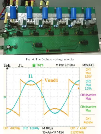
As showed in Fig. 4, the power electronic part is composed of six independent voltage invertors with 6 separate control signals. This inverter consists of six independent full-bridge converters (special integrated circuit) with dead-time and thermal shutdown implemented inside. The outputs of the inverter legs can be connected in parallel or series. Six protection systems are used against overcurrent or short-circuit protection. Technical parameters of this reduced power test bench are expressed
as max DC voltage: 48 V, wide range of switching frequency: up to 100 kHz, and max current: 5A
TABLE I
PARAMETERS OF THE IMPEDANCE MATRIX
i j 1 2 3 1 R (!) 2.27 0 0 L (mH) 2.93 0.086 0.027 2 R (!) 0 2.44 0 L(mH) 0.086 3.15 0.171 3 R (!) 0 0 2.74 L (mH) 0.027 0.171 2.86
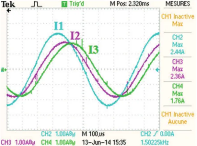
Capacitor bank has been calculated in order to compensate the reactive power on the three phases. This leads to C = [3.74 µF, 3.37µF, 3.75µF]. The switch control signals can be generated either from a pulse generator or from Matlab/Simulink with a digital control board. Moreover, these control signals are isolated from the power stage for safety reasons. For example, inverter voltage n°1 and current are presented in Fig.5, for example while the other currents can be seen in Fig.6.
Fig. 4. The 6-phase voltage inverter
Fig. 6. Inductor currents in phases 1, 2 and 3
In Fig. 3, the load consists of three inductors organized in series configuration and a ferrite core as work piece coupled. A matrix model of the system is given in (7) where sinusoidal currents I1, I2 and I3 feed the three coils
through the three inverters. The so-called “impedance matrix” Z in (8)(9) and (10) carries all the information on the state of the load via its parameters.
!#" !$# !%#& = ' ("+ )*", )-"$, )-$", ($+ )*$,)-"%, )-$%, )-%", )-%$, (%+ )*%, / 0$0##" 0%#& (7) (1, *1: self-resistance and inductance for inductor I, -12: mutual inductance between phase i and j.
34 = 3""5555 3"$5555 3"% 5555 3$"5555 3$$5555 3$%5555 3%"5555 3%$5555 3%%5555& (8) 36,6 5555 = (1+ ),*1 (9) 36,8 55555 = ),-1,2 (10)
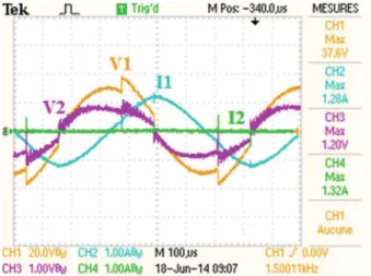
III. IDENTIFICATION BY V/I METHOD WITH PHASE SHIFT In this method, all the three capacitors have been removed for the load to be supplied directly by a sine wave from a frequency generator. Consequently, only resistors, self-inductors and coupling terms are identified. In the first experiment, phase 1 is supplied with a sinusoidal voltage while phase 2 and phase 3 are opened. The necessary values to be measured are V1rms, V2rms, V3rms, I1rms and phase shifts
between V1/I1, V2/I1, V3/I1 in Fig. 7. Then, the impedance
parameters Z11, Z21, Z31 are calculated by (11).
ij i ij ij ij ij j
V
Z
R
jX
R
j L
I
"
!
!
#
!
#
(11)Similarly, measurements on phase 2 and phase 3 will give Z12, Z22, Z32 and Z13, Z23, Z33. It is easy to understand
that this method does not lead to accurate. Indeed, I measurements that could be noisy, will lead to division by a false term and false impedance values, while phase measurements via zero crossing are often difficult to achieve, particularly in an on line automatic mode.
Fig. 7. Voltage V1 (CH1), induced voltages V2 (CH2), V3 (CH3) and current I1 (CH4)
IV. OFF-LINE IDENTIFICATION BY PSEUDO ENERGY METHOD
In the pseudo-energy method, the capacitors are not removed in order to stay in the resonant mode. The identification process is composed of three successive steps during which the 3 phases are supplied independently and successively. This method was first described in [7] in an off-line mode thanks to a specific and complex apparatus (Rogowski coils and Le Croy oscilloscope). It will be first implemented in the off-line mode in real time single board controller, with a reduced sample frequency and 12 bits AD converters. Then, the on-line mode will be presented in section V.
In the first step, phase 1 is supplied by the square voltage generated by the corresponding inverter while phase 2 and phase 3 are opened (their inverters control signals are not activated). Identification of the terms of the first column of matrix Z is achieved. Then, the second step consists in supplying phase j while I2 and I3 are null, in
order to measure the parameters of column 2 in the Z matrix. Finally, step 3 is the same for phase 3. At resonant frequency, a sinusoidal current appears in phase i. The measured values to calculate Rii, Rij, Rik, Xii, Xij and Xik ,
i.e. terms in the first column of (8), are the voltages across the RL parts of phase i, j and k which are Vi, Vj, Vk,
respectively, and current in phase i, named Ii. Current in
phase j and k must be equal to zero in order to cancel the coupling terms in phase i and in (7). Assuming that the voltages and currents are sinusoidal, the following equations can be written. Starting from the same principle as in the classical method, the RMS values of the currents (12) and the voltages are first determined and cos(") is calculated by (13) with n the number of integration periods.
dt i T . n 1 I nT 0 2 rms !
&
(12) j i j i I . V i . v ) cos() !( ' (13) ij nT 0 j i j i v .i dt P T . n 1 i v ' ! ! (&
(14)2 j ij ij
I
P
R !
(15) 2 j 2 ij 2 ij j i I P S X ! % (16) j i ijV
.
I
S !
(17) 2 2 i i i S P Q ! % (18)Of course, accuracy of cos(") and the other terms will be increased with the number of integration periods. The pseudo-power average is given by (14). The coupling terms involving i and j quantities with i#j are called “pseudo-power” because they are the product of currents and voltages that do not necessarily coexist in the same circuit. They represent power in terms of unity but may have no physical meaning. The mutual resistance is obtained by dividing the “pseudo active power” by the square of the corresponding RMS inductor current as described in (15). The calculation of the capacitance or reactance (16) requires the calculation of “pseudo apparent power” (17) which is calculated as the product of the supplied RMS current and the voltage induced. In fact, as it can be easily seen in Fig 8, voltages are not sinusoidal. Consequently, all the measured values have to be low-pass filtered through first order digital filters at the fundamental frequency (1500Hz).
Fig. 8. Phase 1 and 2 voltages and currents during the identification step on phase 1 with modulated angle on inverter 1 and phases 2 and 3 open
circuited. CH1:V1; CH2:I1; CH3:V2 and CH4:I2
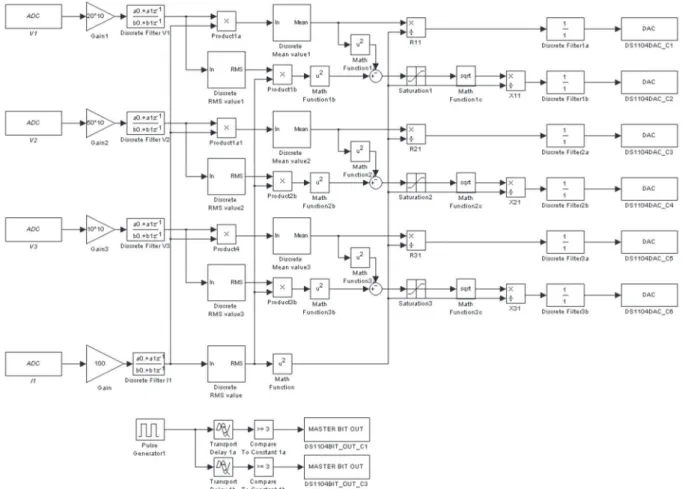
As depicted in Fig. 8 where phase 2 and 3 are open circuited, current in phase 1 is perfectly sinusoidal while the other currents in phase 2 and 3 are equal to zero. The parameter identification runs properly. Fig. 10 gives the bloc diagram which is implemented on the DSP board to measure R11, R21, R31, X11, X21 and X31 parameters during
the first identification step, when phase 1 is supplied and currents should be null in the other phases. The importance of this last point will be discussed later. It will be shown that the system must operate at reduced power just to ensure the currents in phase 2 or 3 will not exist due to the back emf which is generated by the coupling effects
between phase 1 and 2 or phase 1 and 3. In that case, currents will circulate through the reverse diodes of the bridges.
Fig. 9. Phase 1 and 2 voltages and currents during the identification step on phase 1 with reduced current in inverter 1. CH1: V1; CH2: I1; CH3 :V2 and CH4 :I2
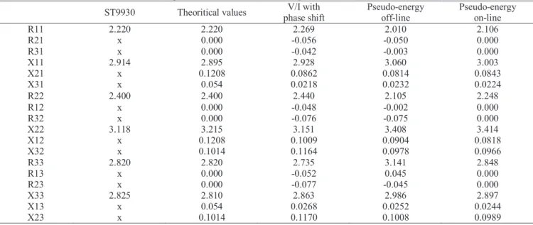
When the control signals of the inverter 2 is OFF, even if the phase 1 voltage is maximum as in Fig. 9, the induced voltage on phase 2 is not higher than the supply voltage. Thus there is no current flowing through the inverter 2 diodes and this leads to good identification results, such as listed in Table IV. Finally, it is worth noticing that these rather good identification results are obtained with a reduced sample period, i.e. only 12 times the fundamental frequency. This consideration will help to reduce the computational burden and is positive for real time implementation of this identification method.
Moreover, capacitors may vary with temperature or may differ from the supplier values given in the data sheet. This method will also provide estimation of C, the capacitor bank as listed in Table II. Voltages across them could be obtained through (19) assuming as previously stated, that voltages across the RL parts are measured with dedicated sensors and filters. Once each inverter voltage can be deduced from the dc bus voltage and the duty cycles, and not directly measured, capacitors derive from (20). Of course, these voltages across Ci are far from sinus and also
need low-pass filtering.
RLi invi Ci
V
V
V
!
%
(19)* +
* +
ci i iV
I
C
"
!
(20) TABLE IIMEASUREMENTS OF CAPACITORS BY THE PSEUDO ENERGY METHOD
Phase $C (,) C (µF) Difference 1 0.032 3.44 -6.9% 2 0.03 3.16 -2.1% 3 0.034 3.65 2.5%
Fig. 10. Bloc-diagram for the identification process on phase 1
V.ON LINE IDENTIFICATION BY PSEUDO ENERGY METHOD Fast identification of the system parameters becomes an objective of dramatic importance in the very particular case of rolling plates. Their characteristics such as type, dimensions, temperature, etc. when placed under the induction generator, can suddenly change. It is particularly true when the industrial process needs to heat two different types of work pieces one after another. Assuming that a warning signal is sent during (or before) the change, the three identification steps can be launched successively, just during the duration of the change, i.e. time for the inductor crossing. Under the assumption of a 1m/s speed of the rolling piece and because each identification step is only few periods long, 100 periods i.e. 66ms for example, the work piece displacement would be no more than 6.6cm, just the dimension of the width of the soldering strip between the two work pieces! As a consequence, the resulting temperature disturbance will certainly be negligible. As seen in Fig.11, when the gate signal at the beginning of the identification step, switches phase 2 and phase 3 from ON to OFF, the corresponding currents decrease down to zero. In order to reduce the estimation error, the number of identification periods Toff must be high compared to the
transients. Moreover, identification must start after the transients. A survey on this value is given in Table III. A convenient value is 100 times the system fundamental period which will lead to 7.2% error.
Because the system is supposed to work at different operating points and with some resonant frequency variations, additional experimental results are provided in Table V with satisfying results. It has been shown in [15] that resonant controllers which have been successfully used in this type of application are robust enough to cope with misalignment and parameter estimation error. Then, control control of the inductor currents will be performed correctly.
Fig. 11. Command signal of identification process (CH1), phase 2 voltage V2 (CH4) and phase 2 current I2 (CH2)
TABLE III
INFLUENCE OF TOFF OF THE IDENTIFICATION RESULTS
toff Time (ms) diference 100.T0 66.7 -7.2%
20.T0 13.3 -25.2%
5.T0 3.3 -31.8%
VI. CONCLUSION
This paper describes a new method for parameter estimation of a multiphase induction heating system. Simulations and experiments were presented in order to measure its impedance matrix for more exact control in closed loop. The “pseudo-energy” method is applied in comparison with the classical V/I method. It achieves good results on a reduced power 3-phase resonant system with voltage inverters, even with a limited sample frequency.
Future work will deal with the on-line application of this method on a 6 phase system and on a real full power induction heating system with transverse flux and concentric coils. Moreover, heating magnetic steel with a non-linear behavior and the corresponding parameter identification will also be an important issue in the future.
REFERENCES
[1] Lucia O., Maussion P., Dede E.J.Burdio, "Induction Heating Technology and Its Applications: Past Developments, Current Technology, and Future Challenges", Industrial Electronics, IEEE Transactions on, Vol. 61, No. 5, May 2014.
[2] Yilmaz, I.; Ermis, M.; Cadirci, I., “Medium-Frequency Induction Melting Furnace as a Load on the Power System”, Industry Applications, IEEE Transactions on, Vol. 48, No. 4, 2012, pp 1203-1214 [3] Millán I., Burdío J.M., Acero J., Lucía O, Palacios D.,
“Resonant inverter topologies for three concentric planar windings applied to domestic induction heating”, Electronics Letters, 46, (17), 2010, pp. 1225-1226
[4] Lucía, O. ; Carretero, C. ; Burdío, J.M. ; Acero, J. ; Almazan, F., “Multiple-Output Resonant Matrix Converter for Multiple Induction Heaters”, Industry Applications, IEEE Trans. on, Vol.48, No. 4, 2012, pp. 1387-1396
[5] Souley M., Caux M., Pateau O., Maussion P., Lefèvre Y., “Optimization of the Settings of Multiphase Induction Heating System”, IEEE Trans. on Industrial Applications, 2013, Vol. 49, N° 6, pp. 1-7
[6] Xu Zhe ; Che Xulong; He Bishi; Kong Yaguang; Xue Anke, “Model Identification of the Continuous Casting Billet Induction Heating Process for Hot Rolling”, Intelligent System Design and Engineering Applications (ISDEA), 2013, Third International Conference on, pp. 942-945
[7] Souley M., Spagnolo A., Pateau O., Paya B., Hapiot J.C., Ladoux P., Maussion P., “Methodology to characterize the impedance matrix of multi-coil induction heating device”, Proc. of the
Electromagnetic Properties of Materials Conference, Germany, 2009
[8] Canova, A.; Dughiero, F.; Fasolo, F.; Forzan, M.; Freschi, F.; Giaccone, L.; Repetto, M., "Identification of Equivalent Material Properties for 3-D Numerical Modeling of Induction Heating of Ferromagnetic Workpieces”, Magnetics, IEEE Transactions on, Vol. 45, No. 3, 2009, pp. 185 –1854
[9] Jimenez, O.; Lucia, O.; Urriza, I. ; Barragan, L.; Navarro, D., “Analysis and Implementation of FPGA-Based On-line Parametric Identification Algorithms for Resonant Power Converters”, Industrial Informatics, IEEE Transactions on, Vol.10, No. 2, 2014 , pp. 1144 - 1153
[10] Lucia, O.; Jimenez, O. ; Urriza, Isidro ; Barragan, L. A.; Mattavelli, P.; Boroyevich, D., “FPGA Implementation of a Gain-Scheduled Controller for Transient Optimization of Resonant Converters Applied to Induction Heating”, IEEE Applied Power Electronics Conference and Exposition (APEC), 2013, pp. 252 –2525
[11] Dominguez, A.; Otin, A.; Urriza, I.; Barragan, L.A.; Navarro, D.; Artigas, J.I., “Load identification of domestic induction heating based on Particle Swarm Optimization” , Control and Modeling for Power Electronics (COMPEL), 2014 IEEE 15th Workshop on, 2014 , pp. 1 - 6
[12] Paesa, D. ; Franco, C. ; Llorente, S. ; Lopez-Nicolas, G. ; Sagues, C., “Adaptive Simmering Control for Domestic Induction Cookers”, Industry Applications, IEEE Transactions on, Volume: 47, Issue: 5, 2011 , pp. 2257 – 2267
[13] Carretero, C.; Lucia, O.; Acero, J.; Burdio, J.M., “First harmonic equivalent impedance of coupled inductive loads for induction heating applications”, IECON 2012 - 38th Annual Conference on IEEE Industrial Electronics Society, 2012 , pp. 427 - 432
[14] Nguyen K.L., Caux S., Teixeira P., Pateau O. Maussion P., “Modeling and parameter identification of a multi-phase induction heating systems”, Conf. on Modeling and Simulation of Electrical Machines, Converters and Systems, Electrimacs 2014, Spain [15] Nguyen, K.L. ; Pateau, O. ; Caux, S. ; Maussion, P. ;
Egalon, J., “Robustness of a Resonant Controller for a Multiphase Induction Heating System”, Industry Applications, IEEE Transactions on Vol.51 , No. 1, 2015, pp. 73 – 81
Table IV: impedance measurements according to different methods (in ,- ST9930 Theoritical values V/I with
phase shift Pseudo-energy off-line Pseudo-energy on-line R11 2.220 2.220 2.269 2.010 2.106 R21 x 0.000 -0.056 -0.050 0.000 R31 x 0.000 -0.042 -0.003 0.000 X11 2.914 2.895 2.928 3.060 3.003 X21 x 0.1208 0.0862 0.0814 0.0843 X31 x 0.054 0.0218 0.0232 0.0224 R22 2.400 2.400 2.440 2.105 2.248 R12 x 0.000 -0.048 -0.002 0.000 R32 x 0.000 -0.076 -0.075 0.000 X22 3.118 3.215 3.151 3.408 3.414 X12 x 0.1208 0.1009 0.0904 0.0818 X32 x 0.1014 0.1164 0.0978 0.0966 R33 2.820 2.820 2.735 3.141 2.848 R13 x 0.000 -0.052 0.045 0.000 R23 x 0.000 -0.077 -0.045 0.000 X33 2.825 2.810 2.863 2.986 2.897 X13 x 0.054 0.0268 0.0252 0.0244 X23 x 0.1014 0.1170 0.1008 0.0989
Table V: impedance measurements at different operating points (in ,-.with the.on-line pseudo-energy method F=1480Hz
I1=1.5A, I2=1.7A, I3=2.2A
F=1500Hz I1=1.4A, I2=1.5A, I3=2.1A
F=1520Hz I1=1.3A, I2=1.4A, I3=2.2A
R11 2.25 2.34 2.59 R21 0.041 0.075 0.045 R31 -0.056 -0.019 -0.1 X11 2.956 2.99 3.3 X21 0.066 0.07 0.078 X31 0.02 0.027 0.033