HAL Id: tel-01525861
https://tel.archives-ouvertes.fr/tel-01525861
Submitted on 22 May 2017
HAL is a multi-disciplinary open access
archive for the deposit and dissemination of sci-entific research documents, whether they are pub-lished or not. The documents may come from teaching and research institutions in France or
L’archive ouverte pluridisciplinaire HAL, est destinée au dépôt et à la diffusion de documents scientifiques de niveau recherche, publiés ou non, émanant des établissements d’enseignement et de recherche français ou étrangers, des laboratoires
based on metamaterials
Yao Gao
To cite this version:
Yao Gao. Experimental study and application of homogenization based on metamaterials. Physics [physics]. Université Pierre et Marie Curie - Paris VI, 2016. English. �NNT : 2016PA066510�. �tel-01525861�
THÈSE DE DOCTORAT DE
l’UNIVERSITÉ PIERRE ET MARIE CURIE
Spécialité
Physique
Présentée par
Yao GAO
Pour obtenir le grade de
DOCTEUR de l’UNIVERSITÉ PIERRE ET MARIE CURIE
________________________________________________________________________
Étude expérimentale de structures basées sur les metamatériaux;
application de l’homogénéisation à ces structures
_________________________________________________________________________
Soutenue le 28 novembre 2016 Devant le jury composé de :
M. Didier Felbacq Rapporteur M. Bruno Lombard Rapporteur M. Marigo Jean-Jacques
M. Bruno Gallas
Examinateur Examinateur M. Pham Kim Examinateur Mme. Maurel Agnès Directeur de thèse M. Ourir Abdelwaheb Co-Directeur de thèse Mme. Habiba Ouslimani Co-Directeur de thèse
1 Introduction 5
1.1 Background . . . 5
1.2 Aim of this thesis . . . 6
1.3 Outline of thesis . . . 7 2 State of art 9 2.1 Metamaterials . . . 10 2.1.1 Introduction . . . 10 2.1.2 Application of Metamaterials . . . 14 2.2 Homogenization . . . 18
2.2.1 Field averaging method . . . 19
2.2.2 Retrieval method . . . 21
2.2.3 Near Resonance method . . . 23
3 Classical homogenization for metamaterials structures at the subwavelength scale 24 3.1 Homogenization for Layered Medium . . . 25
3.1.1 Multilayer Slab . . . 29
3.1.2 Corrugated Surface . . . 31
3.2 Spoof plasmons . . . 35
3.2.1 Corrugated Metallic Surface . . . 36
3.2.2 Experimental Validation of Metallic Thin structure . . . 39
3.3 Application to patch antennas . . . 46
3.3.1 Background . . . 47
3.3.2 Dispersion Relation . . . 48
3.3.3 Reshaping the radiation pattern of antenna . . . 52
3.3.4 Electromagnetic radiation from the finite size metamaterial . . . . 57
4 Classical homogenization of Second Order 61 4.1 Theory . . . 64
4.2 Experimental Validation for Structured Metallic Layers . . . 67
4.2.1 Experiment Set up . . . 69
4.2.2 Results . . . 69
4.3 Application to the tuning of the reflection phase of AMC . . . 80
4.3.1 Theory . . . 82
4.3.2 Validation . . . 83
In order to retrieve effective parameter of the periodic structure, people have made effort to develop the theory of homogenization, which regards the periodic structure as a homo-geneous medium. This thesis mainly focuses on the proposition and validation of classical and second order homogenization. A kind of method for homogenization is applied to ob-tain effective parameters of multilayer structures. Moreover, classical homogenization is adopted to calculate transmission properties of dielectric multilayer structures and the dis-persion relation of metallic cylinder array mounted on a smooth metallic ground plane. From the dispersion relation, its band gap property at a certain frequency band is revealed and is applied to reshape the radiation pattern of traditional patch antenna by suppressing the surface wave propagating on the ground plane. We have published his part of the work in [22].
We experimentally demonstrate one important limitation of classical homogenization when calculating the transmission property of an ultra-thin metallic grating. The mea-sured transmission coefficient is much smaller than that calculated by classical homoge-nization, although the interferences may be caused by the imperfect experiment facility are eliminated. Thus we propose a new second order homogenization, which is able to get the transmission coefficient correspondent to numerical results. Furthermore, second order homogenization has been experimentally validated by several metallic grating with the same dimension except for the thickness. This part of work will be included in a chapter of a book will be published by Intech Publisher.
Introduction
This thesis focuses on homogenization of metamaterials, which are periodic structures ex-hibiting extraordinary properties that do not exist in nature. The structuration of metama-terial being at the subwavelength scale, they can be replaced by equivalent, homogenized material.
1.1
Background
Since 1960s Veselago proposed the conception of negative reflective index metamaterials that exhibit negative permittivity ε and permeability µ, lots of scientists have made effort in this domain. After approximate 30 years, thin wires and split-ring array structures, which have negative ε and µ respectively, are invented. In order to determine the effective constitute parameters, several methods have been proposed.
The first one is to adopt the numerical tools to simulate the effective parameters of metamaterials, since the properties of effective metamaterials can be achieved from sim-ulation by inferring refraction n and relative impedance Z, which can be derived from transmission and reflection coefficients [54]. Finite Element Method (FTDT), Method of Moments (MOM) and Finite Integration Technology (FIT) are applied in the
numer-ical tools such as High-Frequency Electromagnetic Field Simulation (HFSS) and CST Microwave Studio (CST). The second method uses the scattering parameters to retrieve the constitute parameters, which is proposed by Smith et all in 2002 [62]. Actually, re-trieve method is mainly used to dealing with isotropic medium [35, 63]. The third one is so-called homogenization, which allows us to replace the subwavelength periodic struc-tures that have complicated boundary condition with an equivalent and effective medium. [8, 2, 57, 26, 45, 27, 47]
1.2
Aim of this thesis
In this thesis, in order to deal with the metamaterials with one or two-dimensional peri-odic structures, an approximate analytical model is adopted to homogenize the structure to obtain its transmission properties and dispersion relation in a simple and fast way. The metallic material is taken into consideration in the far infrared, thus in a frequency range where metal behaves as an opaque medium. Such metallic arrays are used in the desig-nation of metallo-dielectric structures, as the Artificial Magnetic Conductors used in the design of the antenna, and there is currently renewed interest in such array since they are the key piece of so-called metasurfaces (with a typical resonant behavior as in the mushroom structure of Sievenpiper [60]).
In addition to being able to produce unexpected scattering of electromagnetic waves, these structures can support guided waves, and it is for this property that they have been proposed by Pendry and coworkers [53]; in this context, these guided waves have been called ‘spoof plasmons’ since they mimic, in the far infrared regime, the behavior of plasmons observed in the visible range (plasmons are the wave guided at the flat inter-face between air and metal, and this requires a negative permittivity). In this thesis, this kind of metasurface is used to reshape the radiation pattern of traditional patch antenna by suppressing the guided waves on the metal ground in a certain range of frequency.
Furthermore, the drawbacks of classical homogenization for the ultra-thin structures are reviewed. A new method named the second order of homogenization is investigated.
1.3
Outline of thesis
The overview of this thesis is as follows:
In chapter 2, starting from the basic phenomenon in daily life, the conceptions of wave propagation and metamaterials are introduced. Moreover, a brief history of the develop-ment of metamaterials is reviewed. Several landmark discoveries after the publication of Maxwell Equations are presented, such as the proposition of the idea of metamaterials and the experimental validation of cloaking. In addition, several important applications of metamaterials are demonstrated, such as Electric Band Gap (EBG), High Impedance Surface (HIS) and Left Hand Material (LHM) that is able to realize negative-index. Fi-nally, a short introduction and history of homogenization are shown to provide a general view of the background.
In Chapter 3, classical homogenization is investigated and validated to predict the transmission properties of a multilayer structure. Start from the simplest multilayer struc-ture that consists of two kinds of dielectric layered medium, numerical results is provided to validate the analytical result of multilayer slab and corrugated surface. In order to solve the same problem for a metallic corrugated surface, continuous field condition is taken into consideration to calculate its transmission property. And also, a thin structure can support surface plasmons is experimental validated.
Furthermore, a meta-surface made of a finite array of grounded metallic cylinders is proposed to realize a transmission bandgap is demonstrated. Such a property has been shown to reshape the radiation field of a printed patch antenna. Also, the resonances among the metallic cylinders are analyzed, and the field distributions are shown at differ-ent frequencies.
Chapter 4 starts from a phenomenon of disagreement caused by the method of clas-sical homogenization in calculating the transmission property of an ultra-thin periodic structure. The classical homogenization of second order is thus introduced. Six different prototypes are manufactured to validate the second order homogenization, which proves that classical homogenization can be used only when the thickness of periodic structures is larger than 0.01λ , otherwise, classical homogenization of second order should be em-ployed.
Moreover, investigations of Artificial Magnetic Conductor (AMC) that consists of ultra-thin structures by using interface homogenization are shown. The ”jump” boundary condition was employed instead of bulk region boundary condition to determine the phase shift property of AMC. Experimental validations are given to show that exactly phase shift due to the different thickness of metal layer.
State of art
The periodic phenomenon is the most important basic elements to constitute complicated movements of the world, even the Galaxy. In our daily life, the water wave that we see in the lake or the sea results from oscillation of the surface of water; the sound we hear re-sults from the vibration of the sound source induce the oscillation of the air molecule from distance to excite our eardrum; the wireless video we can see on the screen is because the video information is modulated on the carrier wave that results from the oscillation of the electrons in the crystal oscillator. And, this kind of oscillation of lots of elements causes ”wave”. For example, more than century ago a Germany scientist Hertz experimentally proved the existence of electromagnetic wave. Until now people have found lots of prop-erties and applications such as telecommunication, power transmission, detecting and so on.
Trying to control and tail transmission of the electromagnetic wave in the different medium is always an important and meaningful subject. In the near past several decades, scientists found that not only the properties of the material that we used in the experi-ment is able to affect the wave property. Moreover, the arrangeexperi-ment of the material has advanced impact when tailing the wave propagation, entitling traditional material with extraordinary properties that do not exist in nature.
Normally such arrangement refers to periodic, for which the structure is so-called ’metamaterial’. Moreover, in order to study inner physical mechanism, lots of methods are proposed such as Numerical calculation, Retrieval method, Field averaging method. These methods are briefly introduced in this chapter.
2.1
Metamaterials
2.1.1
Introduction
‘Metamaterial’ is a material composed of a periodic arrangement of metallo-dielectric unit cells at a scale smaller the wavelength of the propagating wave. The ‘meta’ comes from Greek prefix ‘µετα-’, which means beyond. In another word, metamaterials de-scribe those materials can provide original properties that could not be found in nature. For the nature materials, their resonance frequencies mainly rely on the polarization of their molecule, whose dimension is extremely smaller than the wavelength of the incident wave. Although they can resonant in the same mechanism as normal materials, the di-mension of the array and the unit cells is also much smaller than the wavelength of the incident wave. Consequently, designation of the array can affect the resonance property of this structure, which gives us a new method to manipulate the incident wave.
Actually, people’s understanding of the electromagnetism can be dated back to the 19th century when James Clerk Maxwell developed the formulation of Maxwell Equa-tion. After that, scientists have made enormous progress in the telecommunication sys-tem. More importantly, people have an advanced view towards the interaction of the electromagnetic wave and different materials, including metamaterials.
Those extraordinary characteristics of metamaterials do not only rely on the proper-ties of the traditional materials, but also their peculiar designation including geometry, size, and shape, which give them special capable for blocking, absorbing or selecting
waves. Well-designed metamaterials can affect the radiation or propagation of electro-magnetic, acoustic and water waves. As early in the 1960s, a Russia physicist Veselago first proposed the existence of metamaterials [66] Although the mechanism between the electromagnetic wave and metamaterial is not very clear, he predicted that such kind of medium has new capability such as negative refractive index.
In 1990s, engineers experimentally demonstrated thin metal wires array and split ring array, shown in Fig.2.1 (a), which has negative permittivity and permeability respectively. Electromagnetic wave can excite special resonances in these kinds of artificial structure, which is different from those properties in conventional materials.
(a) (b)
Figure 2.1: (a) Split-ring and wires array. (b) Cloaking
In the past decades, one of the most famous conceptions related to metamaterial is cloaking. Lots of scientists and engineers have made effort in such filed. In 2006, Prof. Pendry and his team realized a cloaking can work in microwave frequency [58]. This cloak is made of metamaterials that consist of periodically arranged elements, shown in Fig.2.1 (b), which is able to change the transmission properties of the electromagnetic wave that propagate through the cloak. And consequently, make the stuff placed in the cloaking invisible in microwave frequency band.
Generally speaking, well-designed electromagnetic metamaterials have several ex-traordinary properties that could not be found in nature, shown as following.
1) Single Negative Metamaterials: Single negative metamaterials (SNG) have nega-tive permittivity or neganega-tive permeability. In [73], the authors realize DNG metamaterials by combining two SNG structures. To conduct wave reflection experiments, the slab of negative mu materials and negative epsilon materials have been joined. Like DNG meta-materials, SNGs change their parameters such as refraction index n.
2) Double Negative Metamaterials: Double negative metamaterials (DNG) are the metamaterials that have both negative permittivity and permeability. These are also known as negative index metamaterials (NIM) [15]. Another name for DNGs is left-handed media, because in this kind of medium the electric vector, magnetic vector, and wave propagating vector satisfy the left-hand rule [78].
3) Electromagnetic Band Gap (EBG) Metamaterials: Electromagnetic band gap metamaterials can control wave propagation by tuning the parameter to form a bandgap at certain frequency band. It is achieved either by photonic crystals (PC), or left-handed materials (LHM).
After decades of investigation, there are tremendous kinds of metamaterials are pro-posed, such as:
1, Textured Surface
Textured surface has extraordinary properties in comparison with smooth metallic or dielectric surfaces, such as high impedance, electric bandgap or frequency selective. For example, High Impedance Surface (HIS) is one of the important applications of meta-materials. By coupling a textured surface on the normal smooth metal surface, we can manipulate its radio-frequency electromagnetic property [60]. The typical smooth con-ducting sheet has small surface impedance, however, such kind of textured surface has relatively high impedance. A well-known HIS is a mushroom-like structure, shown in Fig.2.2, designed by Sievenpiper [60]. The structure consists of an array of square metal patches, connected to a metal ground by vertical conducting vias. When the unit cells are much smaller than the operating wavelength, its behavior is similar to resonant LC
Figure 2.2: HIS (a) Side view (b) Top view
circuits, which perform as an electric filter to suppress the current flow along the sheet. Consequently, the surface impedance is very high, and the tangential magnetic field is very small. Such structure can be described as artificial magnetic conductor (AMC).
Figure 2.3: EBG Structure
2, Photonic Metamaterials
Photonic metamaterials are the type of electromagnetic metamaterials that designed to work in optical frequencies. Photonic metamaterials radiate the electronic waves at optical wavelengths. Furthermore, the sub-wavelength period differentiates the photonic metamaterials from photonic band gap structure. This is because the optical properties do
not come from the photonic band gaps, but from a sub-wavelength interaction with the light spectrum. The metamaterials with the capability of zero index of refraction (ZIMs) and negative index of refraction (NIMs) is the active area of research in optical materials.
3, Chiral Metamaterials
A chiral medium is composed of particles that cannot be superimposed on their mirror images [39]. A chiral medium has different responses for a left circularly polarized (LCP) wave and a right circularly polarized (RCP) wave due to the intrinsic chiral asymmetry of the medium [67]. Besides, cross-coupling between the electric field and magnetic field going through a chiral medium is also existent.
Figure 2.4: Different kinds of Chiral metamaterials
2.1.2
Application of Metamaterials
Lots of sophisticated applications of metamaterials including optical fiber, aerospace de-vice, detect sensor and super lens have been proposed and realized in the past decades. Metamaterials are cross subjects involving electrical engineering, electromagnetic, optical antenna engineering, and material science. In the following, several important properties and applications of metamaterials in electromagnetic domain are shown.
1, Left Hand Materials
One of the most typical applications of metamaterials realized by scientists is left-hand materials (LHM). Russia physicist Mandelshtan first theoretically predicted this kind of material in 1940. Almost 30 years later, from Maxwell equation, another physicist Vesolago found that in this special materials, electric vector, magnetic vector, and pointing vector do not satisfy the Right-Hand Rules, but Left Hand Rules. However, no more big progress is made in the following another 30 years. Until 1996, an English physicist Pendry realized a metal wires array, which has negative permittivity. In 1999, he achieved negative permeability by arranging the metal split-ring (SRRs). In 2000, an American physicist D. R. Smith and his team combined those two structures in a proper array and firstly achieved double negative materials (DNM), whose permittivity and permeability are negative.
Actually, all the materials can be separated into four categories by using the positive or negative value of permittivity ε and permeability µ, shown in Fig.2.5. In the first
Figure 2.5: Categories of materials based on the value of ε and µ
quadrant, where ε > 0 and µ > 0, it represents the normal right-hand material, whose electric vector E, magnetic vector H and the wave propagate vector k satisfy the
right-hand material. In the second and fourth quadrant, only one of ε and µ is positive, while the other is negative. Those kinds of material only can support evanescent decaying wave, in another word, waves could not propagate in such medium.
The most important and interesting materials locate at the third quadrant, whose ε and µ are all negative, thus so-called double negative material. It follows the left-hand rules because its wave propagation vector reverses in comparison with normal materials.
This double negative material has many special properties, such as negative refraction index, reversal Doppler Effect. From Snell’s law, when the lights, or electromagnetic waves, propagate against the interface between air and DNM, the reflect energy do not flow on the original direction, however, reverse to the opposite one, shown in Fig.2.6 (a).
(a)Negative fraction index (b)Perfect lens
Figure 2.6: Application of left hand materials
Due to its negative refraction index, when the wave propagation traveling through an LHM slab, the wave would focus on it and then create an image when leaving the slab, which has been realized in the experiment, shown in Fig.2.6 (b).
2, Filter
Because of the bandgap and high impedance property of metamaterials, they can be applied to design microwave devices, such as filter. In 2003, Mart´ın proposed a left hand medium consists of an array of split-ring resonator (SRR) over a coplanar waveguide (CPW) to control the wave propagation along the CPW [41], see Fig.2.7 (a). The SRR
provide a bandgap for the transmission and can be tuned by varying their dimension.
(a)
(b)
Figure 2.7: (a) Split-ring resonator perform as filter to provide band gap for a coplanar waveguide [41];(b) Square C slot act as low pass filter on a traditional transmission line [1].
In 2007, Ali et al presented a low pass filter which provides flat pass band response but slow attenuation transmission [1], by etching a double square C slots on the metallic ground of a transmission line, see Fig.2.7 (b). This kind of structure improves the filter selective, besides it is easy to be manufactured.
3, Antenna
The antenna is one of the most important elements in the telecommunication system, such as radio, broadcast television, radar or wireless computer network. Since the very beginning at the 1880s when Hertz invented dipole antenna, tremendous kinds of antennas are designed for different applications. Due to various requirements, lots of parameters, such as radiation pattern, bandwidth, gain, return loss or even size, are taken into first consideration by engineers and scientists.
However, some defect of antenna comes from the intrinsic properties. For example, the radiation of traditional printed antenna is due to resonance of electromagnetic wave in
the dielectric between radiating patch and the ground plane. Consequently, the size of the patch antenna is hard to minimize. Meanwhile, although horn antenna is able to radiate high power electromagnetic wave, its radiation pattern is not easy to control. Thanks to the realization of metamaterial, engineers have found that by employing metamaterial, many kinds of properties of the different antenna can be enhanced.
1, Radiated Power Enhancement
DNG metamaterials can be used to increase the radiated power of small antenna [77]. A small dipole antenna with radome made of DNG metamaterials has the larger radiated power than the conventional antenna.
2, Directivity Enhancement
Metamaterials have extraordinary property to controls the electromagnetic radiation, thus to confine the originating energy in a small angular [76]. A DNG material can be used to enhance the directivity of the antenna. For instance, the metamaterials antennas decrease the beam width and side lobe ratio [16] and thus enhance the directivity and reduce the return loss of the antenna.
3, Bandwidth Enhancement
Antenna compensated with Metamaterials is able to achieve wider bandwidth as com-pared to the conventional patch antenna [40]. This is achieved by use of superstrate of metamaterials over a conventional antenna or by employing of LHM.
2.2
Homogenization
In the early 1960s, the Geometrical Theory of Diffraction (GTD) was proposed and ap-plied to solve the problem of rays that hit edges, corners or vertical of boundary sur-face [32]. As the development of electromagnetic theory, engineers met more and more complicated problems in reality. Lots of Numerical methods were proposed, such as Finite-difference time-domain method (FTDT), Transmission line method (TLM), Finite
element method (FEM), Method of moments (MOM) and so on. These numerical tools are good at solving the problem of big volume, high frequency, and complicated boundary conditions. However, these kinds of method require high-speed modern computers and relatively long time to solve the problem.
The transmission properties of metamaterials can be determined by another simplified way, because of its periodic arrangement structure. This method is so called ‘homog-enization’, which allows us to replace the subwavelength periodic structures who have complicated boundary condition with an equivalent and effective medium. Motivated by
Figure 2.8: Homogenizaed materials
the development of theoretical physics, the problem related to the periodic small structures was investigated in a perspective of macroscopic view of physical phenomena. Actually, any well-mixture materials, whose basic elements are smaller than a certain scale, can be regard as homogenous materials, shown in Fig.2.8.
2.2.1
Field averaging method
Another way to derive the effective parameter of periodic structures is so called ”field averaging” method, a straightforward way of homogenization presented by Pendry et al. in 2006 [64]. It aims to obtain the average value of the field in the unit cell instead of the field that varies throughout the unit cell. In this method, averaged electric and magnetic
field E and H can be described as ( Hi= d−1
´
H · dxi Ei= d−1´
E · dxi (2.1)where d is the length of the side of unit cell. In another words, E and H can be calculated from line integral of local field in the area of unit cell. Consequently, it resembles a finite differencing of Maxwell equation [64].
Figure 2.9: Unit cell for field averaging
Fig.2.9 shows the definition of averaging field in unit cell of periodic structure. The general idea is that the averaging magnetic field of top surface Hz is parallel to Z axis and
coms from curl of electric field Exand Eywhich lie on the edges of the four cubic lattices.
Besides, electric field Eycan be derived from the curl of magnetic field Hxand Hz on the
edges of the adjacent cubics. In order to develop a general method, Maxwell equation subjected to the periodic boundary condition should be solved to find each mode of local fields. The curl equation of Maxwell is
(
∇ × E = iωB ∇ × H = −iωD
Normally, the unit cell is inhomogenous, thus for a periodic medium, the solution of Eq.2.1 has the form of
g(x) = h(x)exp(iqx) (2.3)
where q(x) is any of the components in Eq.2.1 h(x + d) = h(x) is the periodic function. Thus, in the case of d λ , where λ is the operating wavelength in the effective medium, the averaging field can describe relative accurate field for us to determine its effective electromagnetic parameter.
2.2.2
Retrieval method
The general idea of retrieval method is to obtain the material parameter from its scattering properties such as transmission or reflection coefficient. Here we take 1-D problem as an example, shown in Fig.2.11 the transmission property of slab can be expressed by transmission matrix
Figure 2.10: Scattering parameter on a homogenous 1-D slab
Wt= T ·Wi (2.4)
where Wi= [E, H] is the incident wave, E and H are the complex electric and magnetic
According to [61], the transfer matrix of such a homogenous slab is T = cos(nkd) −z ksin(nkd) z ksin(nkd) cos(nkd) (2.5)
where n is refractive index and Z is wave impedance of the slab. n, Z can be expressed by its permittivity ε and permeability µ:
ε = n/Z, µ = nZ.
Thus, the scattering matrix related to the transmission coefficient can be obtain by using T matrix [61]: S21= 2 T11+ T22+ (ikT12+T21 ik ) S11= T11− T22+ (ikT12− T21 ik ) T11+ T22+ (ikT12+T21 ik ) S22= T22− T11+ (ikT12−T21 ik ) T11+ T22+ (ikT12+ T21 ik ) S12= 2 det(T ) T11+ T22+ (ikT12+ T21 ik ) (2.6)
for the homogenous material, we have T11 = T22 = Ts, det(T ) = 1 and S is symmetric,
thus S21= S12= 1 Ts+ 1 2(ikT12+ T21 ik ) S11= S22= 1 2(ikT21− T12 ik ) Ts+ 1 2(ikT12+ T21 ik ) . (2.7)
Consequently, n and z can be achieved by inverting Eq.2.7 n= 1 kdcos −1[ 1 2S21 (1 − S211+ S221)] Z= s ((1 + S11) 2− S2 21 (1 − S11)2− S2 21 ). (2.8)
This is the typical retrieval method to describe a homogenous slab. Generally speaking, retrieval methods is widely used because its easy way to retrieve the effective parameters of the medium in a macroscopical view such as permittivity, permeability and magneto-electric coupling coefficient of the bianisotropic metamaterial [37].
2.2.3
Near Resonance method
Actually, there are several kinds of methods to homogenize the periodic structures, for instance, the retrieval method, are well established. However, their solution based on a two-dimensional method that ignoring the case of a linear polarized magnetic field. Thus confine their application to infinite cylindrical obstacles. GUY and his team proposed a dielectric structure performing a full three-dimensional asymptotic analysis [8].
In their method, they focus on the problem of complex medium in 3-D geometric domain, denote by Ω. The periodicity between the unit cell that cause diffraction by fast oscillating behavior when the wave propagate in it is infinitesimal, denotes by h, shown in Fig. As demonstrated in [7], they proved that the structure behaves as local material is
Figure 2.11: Diffracting structures
Classical homogenization for
metamaterials structures at the
subwavelength scale
Metamaterials have promoted many research interests in the last decades because of their extraordinary properties that do not exist in nature to tail wave propagation in several domains such as electromagnetic, acoustic or water waves [9]. The most common meta-materials are made of periodic structures. When the spatial period of the structure is of wavelength size, the structures are referred as photonic or phononic crystals. When the scale of the periodicity is much smaller than the operating wavelength, the struc-tures are considered as metamaterials. Homogenization approaches are preferred for the modeling of these metamaterials. In this case, an equivalent homogeneous (and possibly anisotropic) medium is taken into consideration. The classical homogenization is applied in the low-frequency regime assuming that all wavelengths involved in the structure are larger than the periodicity [3, 46, 47]. Extensions of this classical homogenization have been proposed, known as high frequency homogenization [12, 27] or high contrast ho-mogenization [17]. Alternatively to these hoho-mogenization methods, retrieval methods[20]
or theories of effective medium [53, 31] are also commonly used.
The electromagnetic homogenization for natural and artificial materials has a long history, and lots of theories are proposed to design effective constitutive parameters of the periodic structure. By averaging the microscopic field at the atomic or molecular scale, we can get the definition of permittivity and permeability; with the same idea, by using a proper method to average the field in the artificial periodic structure with a relatively large scale to avoid solving the fields of each unit cells, such method is known as ‘homogenization’[47]. Here, the relatively large scale actually is a limitation for which the wavelength of the wave should be always much larger than the periodicity of the structure.
With such limitation, this method can accurately solve the field of artificial structures with less CPU time than the traditional numerical ways. One of the simple homogeniza-tion techniques is so called retrieving method, which is able to get the effective parameters from the scattering parameters of a metamaterial sample. For example, the Nicholson-Ross-Weir (NRW) retrieval method assumes the equivalence between a complex periodic structure and a simple slab of the same thickness, usually limited to permittivity and per-meability. [17, 11].
3.1
Homogenization for Layered Medium
In this section, the capability of classical homogenization to predict the transmission prop-erty of layered structure at the sub-wavelength scale is demonstrated. The periodic inter-faces in the real problem are replaced by a slab of a homogeneous medium, with an effective mass density tensor and an effective bulk modulus. Thus, explicit dispersion relation can be derived, corresponding to guided waves in the homogenized problem [47]. Homogenization approaches provide effective parameters by considering the permittivity ε , permeability µ of the materials and the geometry of the microstructure, which is
dif-ferent from the retrieval methods. As we mentioned before, a periodic structure can be regarded as effective medium, as long as the periodicity of the structure is much smaller than the wavelength of the electromagnetic wave. Classical homogenization related to periodic structures in this thesis should satisfy kh 1, where k is the wavenumber of EM wave and h is the periodicity of the structure. Next, the simplest one dimension periodic multilayer structures are first taken into consideration. Secondly, analytical expression and numerical validation are given to describe the transmission property of EM wave in such medium.
Multilayer medium
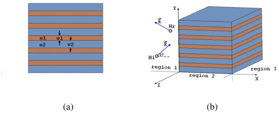
In the following, we calculate the field in a layered structure that consists of two kinds of penetrable dielectric for electromagnetic waves, shown in Figure.3.1(a). Transmission property of such structure described by an analytical expression derived from Helmholtz Equation is given. Furthermore, the result reveals that the transmission property can be strongly affected by not only the permittivity of the materials but also the filling fraction of the two dielectrics.
Consider a plane wave propagating in the free space, the magnetic field H can be obtained from the Helmholtz Equation
∇ · [a∇H(x, y)] + k2bH(x, y) = 0, (3.1)
where a = 1/ε and b = µ, ε and µ are permittivity and permeability of the medium respectively. Magnetic field can be described as:
H(~r,t) = H0· ej(~k·~r−ωt) (3.2)
where ω is the angular frequency of the plane wave, H0 is the amplitude of vector of
H(~r,t), and ~r is the position vector of H(~r,t), ~k is the wave vector of the propagating wave. From the theory of electromagnetic fields, we know that in the free space the
electronic fields E(~r,t) and magnetic fields H(~r,t) are mutually perpendicular, and also E(~r), H(~r) and~k satisfy the right handed screw rule as E(~r) × H(~r) =~k, consequently, the electric field E(~r,t) can be expressed as E(~r,t) = E0· ej(~k·~r−ωt).
Before the study of the metamaterials, it is necessary to make it clear for the different plane waves. Mechanical waves are distinguished by the different oscillation direction of the particles. For example, acoustic waves are defined as ”longitudinal” wave since those molecules in the air vibrate along the direction of sound propagation. On the contrary, water waves are defined as ”transverse” wave because the surface of water vibrate up and down, which is vertical to the wave propagation direction. From such definition, electromagnetic wave is transverse wave.
Circular and linear polarizations are two kinds of transverse plane wave. Electric or magnetic field vectors are often used to describe the variation of the fields. Once the start point of the electric vector is fixed at a specific point, the track of the end of the vector travels along a circular path when the circular polarization wave propagates; otherwise, the track of the end of the vector travels along straight line and go back and forth, the wave is linear polarized. Since the circularly polarized wave can be composed of two linear polarized waves [34], in this thesis only the linear polarized transverse waves are taken into consideration for simplicity.
For electromagnetic waves, the electric and magnetic field, which are always perpen-dicular to each other in free space, are transverse to the propagation direction. In the transverse electric (TE) mode, the electric field is transverse to the direction of propaga-tion while the magnetic field is normal to the direcpropaga-tion of propagapropaga-tion. In our calculapropaga-tion, we take transverse magnetic (TM) mode into consideration, whose magnetic field is trans-verse to the direction of propagation.
Figure 3.1 (a) shows the side view of a grating that we considered. An alternating layers, whose thickness are w1 and w2, of two non-magnetic dielectric material (with
(a) (b)
Figure 3.1: (a) Side view of multilayer medium and (b)Three dimensional slab and the wavevector
To begin with, we take TM incident wave into consideration. Thus the magnetic field can be written as H = H0ej(~k·~r)with~r = (x, y), where the time-dependence e− jωt was omitted
because we do not take the variation of the field correspondent to time, then H should satisfies Helmholtz Equation shown in Eq.3.1.
We know that for this multilayer structure, in the principal directions of anisotropy (x,y), shown in Figure.3.1, a is a diagonal tensor and denoted [18, 43] :
a= 1/ε|| 0 0 1/ε⊥ (3.3) where 1 ε|| = w1 w1+ w2 1 ε1 + w2 w1+ w2 1 ε2 and ε⊥= w1 w1+ w2 ε1+ w2 w1+ w2 ε2
b= 1 inside dielectric medium, including the air. It means that such sub-wavelength layered grating can be described as an anisotropic homogeneous medium by using the homogenization theory of multilayers structure, and the effective permittivity along the two axis can be affected by the geometry parameters.
In the following part, to begin with, several different periodic layered structures are demonstrated and analyzed. Moreover, experimental results are provided to validate these theoretical predictions as well.
3.1.1
Multilayer Slab
In order to calculate the transmission property of such multilayer structure, and make it possible to realize in the experiment, a slab of grating that consists of two kinds of medium layered along the Y axis is mounted in region 2, shown in Figure.3.1 (b). Region 1 and 3 are free space respectively, where εr= 1 and µr= 1. To determine its transmission
property such as reflection or transmission coefficient when it was exposed in TM incident wave, from Eq.3.1 and Eq.3.3, Helmholtz Equation can be written as:
∇ · 1/ε|| 0 0 1/ε⊥ ∇H + k2H= 0 (3.4)
where H = H0· exp(− jkxx− jkyy) in Cartesian coordinate system, kx and ky are the x
and y components of wavevector along X and Y axis respectively. The multilayer slab in region 2, shown in Figure.3.1(b) can be homogenized into an anisotropic medium. And the effect permittivity along X and Y axis have be given as ε|| and ε⊥ respectively[44]. We assume that in both region 1 and 2 of Figure.3.1 (b), the total magnetic field H1and
H2 consist of the incident wave and reflected wave. From the Law of Reflection, we know that wave vectors of incident and reflected wave have the same X and Y component in both region 1 and 2. In the other hand, the magnetic field in region 3 only has the transmission wave. Consequently, we can have the expression of magnetic field in each region as following: ( H1 = H0· e − jk1xx− jk1yy+ R · H 0· ejk1x− jk1y H2 = A· H0· e− jk2xx− jk2yy+ B · H0· ejk2xx− jk2yy H3 = H0· T · e− jk3x(x−l)− jk3yy (3.5)
where k1x, k2x, k3x are the X component of wave vector, k1y, k2y, k3yare the Y component
of wave vector. So, e− jk1xx and ejk1xx are the X component of those waves propagate to
two opposite directions. A and T are the transmission coefficient in region 2 and 3, R and B are the reflection coefficient in region 2 and 3 respectively.
From the continuity condition of the field, we know that the filed on the boundary of two medium should be continuous. Besides, the first-order derivative of field along the normal vector of the boundary should also be continuous. Together with Eq.3.5, we can have two set of combined equations:
( H1(0−, y) = H2(0+, y) H2(l−, y) = H3(l+, y) (3.6) and ( ∂xH1(0−, y) = 1 ε|| ∂xH2(0+, y) 1 ε||∂xH2(l −, y) = ∂ xH3(l+, y) (3.7) we can get ( k2y= k3y= k1y= k1sin θ k3x= k1sin θ k2x= t0k1, where t0= q (1 − 1/ε⊥sin2θ )ε|| (3.8)
Furthermore, transmission and reflection coefficient are achieved as :
( T = 4Zre jk1cos θ LM (1 + Zr+ M − MZr)(1 + Zr− M + MZr) R= (Z 2 r − 1)(M2− 1) (1 + Zr+ M − MZr)(1 + Zr− M + MZr) (3.9) where M = e− jk1t0l and Z
r = ε||cos θ /t0 is the relative impedance of the homogenized
grating with respect to the air.
In the case of TE waves (E = E(r)ˆz), we have
from which the homogenization gives an equivalent isotropic medium
∇ · ∇E + k2εe f fE= 0, with εe f f = ε⊥ (3.11)
So with the same method, we can get the dispersion relation as k2x=
q
1/ε||− sin2θ and Zr= cos θ /t0, and the transmission and reflection coefficient can be expressed as the same
formation with Eq.3.9.
3.1.2
Corrugated Surface
Compared to the multilayer structures that we demonstrated before, corrugated surfaces have more sophisticated configuration and provide interesting applications. In this part, we are going to show our homogenization approach can be applied to corrugated surfaces. We consider the corrugation surface shown in Figure.3.2. With the same previous method, region 2 of Figure.3.2 (a) can be treated as a multilayer slab and modeled as we did in last section.
(a) (b)
Figure 3.2: (a)Corrugated surface (b) Homogenized corrugated surface
The expressions of the fields and boundary conditions have been proposed in the last section. The corrugated surface model can be achieved by replace the medium in region 3 with layer 1 in Figure3.1 (a), whose permittivity is ε1. So it is not difficult to get the
reflection property of such structure from Eq. 3.5 and Eq.3.6. For the TM incident wave, we can get the expression of transmission and reflection coefficient
( T = 4exp j √ ε3µ3−sin2θ k1LZ 1M (Z1Z2+ 1)(1 − M2) + (Z 1+ Z2)(1 + M2) R= (Z1Z2− 1)(1 − M 2) + (Z 1− Z2)(1 + M2) (Z1Z2+ 1)(1 − M2) + (Z 1+ Z2)(1 + M2) (3.12) where ( M= e− jt0k1L Z1= ε||cos θ /t0, & Z2= ε|| q ε3µ3− sin2θ ε3t0
3.1.3
Slanted Slab
In the past two sections, we have studied the transmission properties of grating and cor-rugated surface, whose slabs or teeth are parallel to the horizontal axis. In the following, more practical structures are proposed. The orientation of the slab is not along the x axis whereas with slanted angles α, as is shown in Figure.3.3
Figure 3.3: Slanted Multilayers slab and Corrugated surface
Here, the thickness of the dielectric slab and the periodicity are exactly as the multi-layered slab that we mentioned in the past section, and when the slanted angle α = 0, this
problem is simplified as the situation that we have solve in section 3.1.1 and 3.1.2. From what have been done in last section, the field in the slab can be written as the solution of Helmholtz Equation, shown in Eq. 3.1. On the contrary, the tensor a is not diagonal ma-trix shown the Eq.3.3, but a symmetrical diagonal mama-trix. From the work in [47], under this condition the tensor can be written as
a= ax axy axy ay (3.13) where ( ax ≡ aosin 2 α + aecos2α ay ≡ aocos2α + aesin2α , axy ≡ (ae− ao) cos α sin α (3.14) and ( 1 ao = w1 w1+ w2 1 ε1 + w2 w1+ w2 1 ε2 . ae = w1 w1+ w2 ε1+ w2 w1+ w2 ε2 (3.15)
Thus the Helmholtz Equation 3.1 can be written as
∇ · ax axy axy ay ∇H + k2H= 0 (3.16)
In the last section, the multilayer slab in the region 2 is symmetric, so we assume that in this region the transmit and reflect wave share the same absolute wavenumber value along x axis, but with the different sign of them because of the reversed propagation di-rection. Besides, such assumption is proved in the result of dispersion relation. However, in slanted situation with slanted angle of α, this assumption should not be made arbitrarily like this, on the other hand we use k+2 and k−2 as the wavenumber along axis for the two
waves of different propagating direction as follows: ( H1 = H0· e − jk1xx− jk1yy+ R · H 0· ejk1x− jk1y H2 = A· H0· ejk+2xx− jk2yy+ B · H 0· ejk − 2xx− jk2yy H3 = H0· T · e− jk3x(x−l)− jk3yy (3.17)
With the same method to calculate the field in the multilayer slab in Eq.3.5, we can get the scattering properties. The continuity relation at the interfaces y = 0 and y = l are imposed by the structure of Eq. 3.1, namely the continuity of the field H and the continuity of the normal component of the vector [a · ∇H], which lead to
(
H1(0−, y) = H2(0+, y) ax∂yH1(0−, y) = ax∂xH2(0+, y) + axy∂yH2(0+, y)
H2(l−, y) = H3(l+, y) ax∂xH2(l−, y) + axy∂yH2(l−, y) = 1/ε3∂xH3(l+, y)
(3.18)
Therefore we can get the dispersion relation and the each wavenumber along different axis for this slanted multilayered slab:
( k3y= k2y= k1y= k1sin θ , k3x= t03k1 t03= q ε3µ3− sin2θ k2x+ = k1[− axy ax sin θ + 1 ax q (axysin θ )2− axaysin2θ + axµ3] k2x− = k1[− axy ax sin θ − 1 ax q (axysin θ )2− axaysin2θ + axµ3] (3.19)
where µ3,ε3are the permeability and permittivity of the medium in region 3. From Eq.3.5,
Eq.3.18 and Eq.3.19, the transmission properties of the plane wave propagating in this slanted multilayer can be found as:
( T = 2M(Y1+Y2) (1 − X1+Y2+ X1Y2) − (1 − X2−Y1+ X2Y1)M2 R=(1 − X1+Y2− X1Y2) − (1 + X2−Y1− X2Y1)M 2 (1 − X1+Y2+ X1Y2) − (1 − X2−Y1+ X2Y1)M2 (3.20)
where
( M= e
− jLt2k1
X1= (axt0+ axysin θ )/ cos θ Y1= ε3(axt0+ axysin θ )/t03
X2= (axt0− axysin θ )/ cos θ Y1= ε3(axt0− axysin θ )/t03
The calculation of different kinds dielectric layered structures is shown in the past sections. In the following part, metallic structures are investigated. Besides, spoof plas-mons phenomenon, which can be supported on the textured metallic surface is briefly introduced.
3.2
Spoof plasmons
Surface plasmons (SPs) are electromagnetic surface waves propagating along a metal-dielectric interface that can be observed in the visible wavelength regime. SPs have been proposed for tailoring the light propagation at sub-wavelength scale thanks to the strong confinement of light at the metal-dielectric interface [14]. In 2004, Spoof Surface plas-mons (SSP) were proposed to engineer SPs at THz and microwave frequencies [53]. This result has been obtained by cutting grooves on a scale much smaller than the wavelength to increase the penetration of the fields into the metal.
Corrugated surfaces are able to support the propagation of surface waves in the mi-crowave regime. The existence of spoof plasmons has been proved experimentally[28]. The periodic subwavelength structure that confined electromagnetic field is investigated in microwave and THz waveguide[68]. The properties of these surface waves mainly de-pend on the geometry of the corrugations. Such spoof plasmons solutions can be obtained by the previous homogenization approach.
3.2.1
Corrugated Metallic Surface
In the following part, the simplest 1-D textured metallic surface is studied, furthermore, transmission property of such structure will be derived from the method that we used for the dielectric configurations. Figure.3.4 shows the side view of the 1-D corrugated metallic surface whose periodicity is h = 3mm with metal fraction ϕ = 2/3. However, the method that we deal with metallic layers is different from of dielectric materials, because of its impenetrable property for eletromagnetic waves.
Figure 3.4: Metallic Corrugated Surface
From the electromagnetic theory, we know that magnetic field H satisfy ∆H + k2H= 0 in the air, and in the single substance material, no matter metal or dielectric, magnetic field H satisfy a∇H + k2bH = 0. For the dielectric medium, a = 1/ε and b = µ(µ = 1) for non-magnetic material, but for the metal, there is not a clear value for permittivity, since from the definition of the permittivity of metal it is infinite. Here, we have to find the value of a and b for metal before the next step.
Figure.3.5 is the sketch map for the interface between smooth metal (region 2) and air (region 1). The two kinds of boundary conditions on the interface can be written as
(
H|A = H|B
∂nH|A = a∂nH|B
(3.21)
Since there is no explicit way to get the a and b, if we can give a specific value for both of them which can satisfy the phenomenon that we observed, then we can safely regard
Figure 3.5: Interface of smooth metal and air
such value as a and b. Here, we assume that a = b = 0. We shall lose the information of H inside the region B. Fortunately, there is not necessary and impossible for us to determine the field inside the metallic material. However, for the Second boundary condition, we can get ∂nH|A= 0, which tell us that the partial differential of H along the normal vector
of the interface is ZERO, which can be proved in the experiment. So, it is safe for us to apply a = b = 0 for the calculation related to metal. Next, the multilayer metallic slab is studied by using the classical homogenization.
Obviously, the magnetic field is zero within the metal, and on the interface, the fields meet Boundary Condition.
Thus the main propagation equation in this anisotropic medium can be derived from
∇ · 0 0 0 φ ∇H + φ k2H= 0 (3.22)
and then, in the air the propagation equation can be written as
∆H + k2H= 0 (3.23)
equations, and find that (
H= e−α(y+L)+iβ x for y > L
H= A cos(Ky)eiβ x for 0 < y < L
(3.24)
which can satisfy the boundary condition. By applying the continuity for the perpendicu-lar component of H on the interface φ ∂1H(x, L+) = ∂1H(x, L−), the dispersion relation is
obtained :
β = k r
1 + (1 − φ )2cos2 kL
cos α , where tan(kL) < 0. (3.25) Fig.3.6 shows the dispersion relation of metal corrugated surface, where β is the x
com-Figure 3.6: Dispersion Relation of metallic corrugated surface, whose peri-odic is h= 21mm, filling fraction is phi = 1/7, and length of the cylinder is L= 27mm.
ponent of the wave vector in the corrugation, f is the frequency. The blue line describes the dispersion relation of corrugated metallic surface. Meanwhile, the dot line is the light line in free space. The curve of dispersion relation of corrugated surface is lower than the light line, which means that for the same frequency, the wavenumber in the corrugated surface is larger than that in the free space. In another word, we can tail the wavelength by using this kind of structure on the metallic surface.
3.2.2
Experimental Validation of Metallic Thin structure
Vertical thin cylinder arraySurface plasmons cannot be supported by the smooth electric conductor at frequency band lower than the optical spectrum. From the investigation in the last section, the cor-rugated metal surface is able to sustain ”spoof surface plasmons” at microwave frequency band, which has similar properties with the real surface plasmons that mainly due to its geometry, but also was restrained to be applied to some portable or miniaturized situation. Actually, there are several kinds of structures are able to support spoof plasmons.
Recently, a split-ring resonator designed to sustain spoof plasmons was proposed in [50]. A planar waveguide based on the element of the split-ring resonator is numerically analyzed to show high out- and in-plane confinement. Moreover, in [59], the concept of conformal surface plasmons (CSPs), surface plasmon waves that can propagate on ultrathin and flexible films too long distances in a wide broadband range from microwave to mid-infrared frequencies.
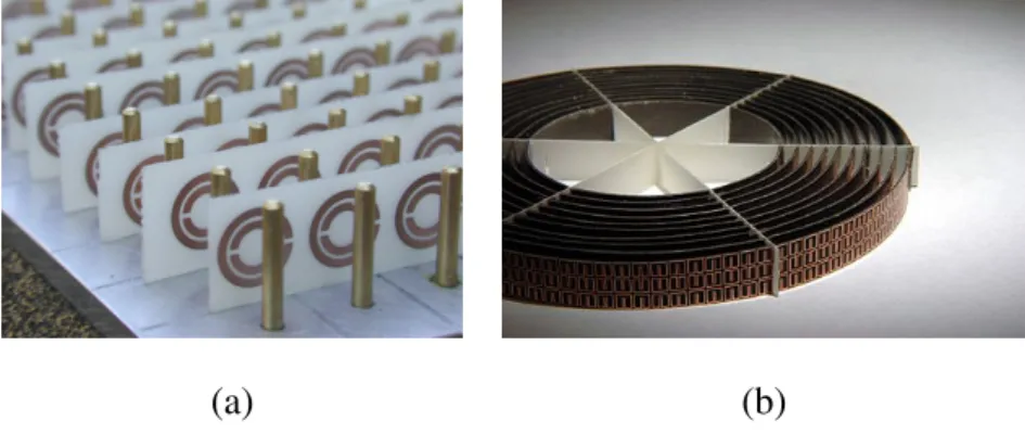
The aim of this experiment is to demonstrate the capability of the printed array to sup-port spoof plasmons on the surface of a metallic ground plane. The rods of the proposed structure are made here by bolting cylindrical screws in a metallic plane. The schematic view and a photography of the designed structure are shown in Fig.3.7. The length of the screws is L = 27 mm and their diameter is 3 mm. They are disposed of in a one-dimensional array using a lattice constant of a=21 mm.
The array is mounted on a metallic ground plane that is placed next to a waveguide which is used to produce surface wave on the metallic ground, see Fig.3.8 (a). The detec-tor is fixed on a modetec-tor that can move along the horizontal bar, which is mounted to another motor. The second motor is able to move along a fixed vertical, shown in Figure.3.8 (b). The field distribution near the array can be measured when the two motors moving corre-spondent to each other.
Figure 3.7: The schematic view of the three dimensional structure composed of an array of rods disposed on a metallic plane (L = 27 mm and h = 21 mm).
(a) (b)
Figure 3.8: (a) A photography of the realized structure and the setup used for the experimental characterization. (b)Experimental facility to measure the field distribution near the cylinder array.
The dispersion diagram of this structure is presented in Fig.3.9. Branches that sup-port very large wavenumbers (β ) compared to free air wavenumber (β0) can be obtained.
These solutions correspond to the sub-wavelength waves that can propagate on the struc-ture usually called spoof-plasmons.
Fig.3.9 shows that spoof-plasmons providing a sub-wavelength propagation can be obtained with the proposed structure. The wavelength of these guided waves is compa-rable to the one in free space at low frequencies. This wavelength becomes smaller and smaller when increasing the frequency. The smallest values that can be observed for the
Figure 3.9: The dispersion diagram of the considered structure.
first branch are near 1.9 GHz. One can also notice that an electromagnetic band gap is imposed by the structure between 2 and 5 GHz.
In order to characterize the proposed structure and provide a validation of the the-oretical prediction, the experimental setup presented in Fig.3.8 (b) is used. We use a microwave waveguide to excite the array by near-field coupling. A small loop antenna is then used to measure the magnetic near field in a plane parallel to the rods and disposed at a distance of 5 mm.
through the proposed structure using two waveguides. A transmission band can be ob-served above 2 GHz, while an electromagnetic band gap is obtained above this frequency. This result is consistent with the dispersion relation, calculated by the homogenization approach presented previously, given in Fig.3.10 (b).
(a) (b)
Figure 3.10: The dispersion diagram of the considered structure.
The measured magnetic fields at different frequencies are presented in Fig.3.11. We can see that when increasing the frequency, smaller wavelengths can be obtained. This result is consistent with the theoretical prediction for the first branch. Moreover, the elec-tromagnetic band gap can be observed above 2 GHz. This is shown in the last presented field, measured at 2.1 GHz.
Another simple validation of these experimental results compared with the theoretical calculations can be made by evaluating the wavelength of the spoof-plasmon at each fre-quency. The obtained results are summarized in the table below. These results show the good agreement between the theoretical predictions and the experiments.
Figure 3.11: The magnetic field distribution measured at different frequencies [1.5 (a), 1.7 (b), 1.9 (c) and 2 GHz (d)] using a small loop probe at a distance of 5 mm from the structure.
Table 3.1: Comparison between the calculated and the measured wave-lengths. Frequency (GHz) Calculated (Dispersion relation) wavelength (m) Measured wavelength (m) 1.5 0.18 0.19 1.7 0.11 0.125 1.9 0.05 0.07
Slanted thin cylinder array
The aim of this experiment is to demonstrate the different band gap of the cylinder array with different slanted angles, shown in Fig.3.12 (a). In order to show the different transmission property of one dimensional thin cylinder array, the prototypes are mounted on a metallic ground plane that is placed in the middle of two waveguide, shown in 3.12 (b).
(a) Vertical and Slanted Thin Cylinder Array (b) Test of Transmission
Figure 3.12: (a) Both of the two kinds of cylinder array with the same pe-riodicity of h = 6mm, diameter of l = 1mm and the same value of length L= 17.5mm, besides, the second one with slanted angle of α = 50o. (b) Ex-perimental facility to measure the transmission between the two waveguide.
results
By employing Eq.3.25, we established in section 2, dispersion relation of these two kinds of cylinder array can be derived, shown in Fig.3.13 (a). From dispersion relation curve of vertical array, it is clear that there is band gap introduced by this structure above 4GHz, represented as the gray area named ‘Band gap 1’. Beside, the slanted array with 50 degree angle has ‘Band gap 2’ that is above 2.6GHz, shown in Fig.3.13 (a).
The measurement results are depict in Figure.3.13. The black curve is the transmission of the vertical array, which goes up as the frequency increases from 2.2GHz to 2.9GHz, and remains high transmission until 3.6GHz. At around 4GHz, a band gap is appeared, whose transmission is lower than 0.4. The red curve stands for the transmission of slanted array. However, clear band gap at 2.75GHz is observed, which is at lower frequency
(a) (b)
Figure 3.13: Dispersion relation and transmission property of the two kinds of one-dimensional array
than that of vertical array. Such phenomenon is mainly because the longer length of the cylinders. Although the hight of he arrays are equal, the effective length for the slanted array is larger and induces a lower resonance frequency. This phenomenon can be used
for the miniaturization of microwave and optical devices based on spoof plasmon.
3.3
Application to patch antennas
In the former sections, analytical predictions, numerical and experimental validation for multilayer and thin structure are provided. At the end of the last section, the property of the metal cylinders to support or suppress EM wave is roughly demonstrated. Next, we are going to investigate into details of such ability, which can be applied to a radiating source to enhance the performance of antennas.
*The aim of the work in this part is to apply the metasurface that we have studied to enhance the directivity of the traditional antenna. Besides, it has been published in [22]. We insert the paper here just after page 45 for the reader who wants get more details, or the reader can skip this part and go back to the manuscript.
3.3.1
Background
Electromagnetic radiating sources involve planar structures susceptible to support surface waves. These waves are bounded to the interface, they diffract in free space when prop-agating to the edges of the ground plane. This mechanism is used as the main radiating mechanism in the traveling-wave antennas (or leaky-wave antennas) based on the design of a guiding structure enable to efficiently couple the surface waves to free space. It is in contrast to resonant antennas, which employ resonances of radiating elements (as monopoles or dipoles). However, even in this case, surface waves are involved but in an undesirable way. Indeed, such antennas are mounted over a larger plane surface (the ground plane), which is susceptible to support surface waves, as surface plasmons for a metallic ground plane in the optical frequencies. The antennas are designed by consid-ering an infinite ground plane that is ignoring surface wave radiation. Because of the finite size of the ground plate in the practice, the surface waves are scattered, and thus, interact with the field of the radiating elements. It results in the appearance of undesired ripples and high-level side lobes in the radiation pattern, responsible for a decrease in the overall performances of the antenna. To avoid such perturbations, one has to prevent the wave propagation on the ground plane. This means that the surface waves have to be associated with a dispersion relation with frequency ranges where the propagation is prevented, namely with band gaps. Lots of work have been done to show the ability of the textured surface to suppress surface wave on the interface between the electric conductor and another medium. In 1999, two designs of improved antennas were proposed [24, 60], where the planar interface of the ground plane is replaced by a periodically structured in-terface. In the former reference [24], the structure consists in piercing a square array of air columns in a dielectric substrate. The array being at wavelength scale realizes a photonic crystal type substrate, which presents a forbidden band gap at the Bragg frequency. In the latter reference [60], the forbidden frequency band is realized using a mushroom-like
array designed at a subwavelength scale.
The concept of surface impedances is used to characterize the response of the struc-ture, resulting in the so-called high impedance surfaces, associated with forbidden fre-quencies for the surface waves. The effect of the excitation of surface waves on radiating elements has been studied in many contexts [33, 72]. Recently, a microstrip patch antenna array and a beam-scanning circularly polarized antenna based on the spoof plasmonic waveguide of a blind-hole array, which can efficiently convert spoof plasmon waves into free-space emissions, have been realized [71, 4]. A review on the application of structured surfaces to control spoof plasmon waves can be found in [70].
3.3.2
Dispersion Relation
1-D structure
In this section, we follow the idea of using the dispersion relation of surface waves to enhance the directivity of printed antennas. Here, we consider the surface waves, usually called spoof plasmons that we have introduced in section 2, guided at the corrugated interface of a perfect conductor, which consists of rectangular grooves with height L and volume fraction of air ϕ, shown in Figure.3.14. In this case, the dispersion relation of the spoof plasmons, derived in [31] for acoustic waves and in [53, 23] for electromagnetic waves with transverse magnetic polarization (the unit vector of H(x, z) along y axis, shown in 3.14) gives
kSP= k
q
1 + ϕ2tan2kL, for tan kL > 0, (3.26) where kSPis the wavevector of the spoof plasmon along x and k the wavenumber in air (or
say, the frequency). Note that the restriction to tan kL > 0 is not mentioned in [31, 53, 23] although it is essential to define the band gaps, and it can be obtained by using classical homogenization technique [44, 47]. The wavefield in air is H(x, z) = H0eikSPx−αz, with
leading to the usual first total band gap is for π/2L ≤ k ≤ π/L [47]. In the following, we refer to the forbidden frequency range, the corresponding range of frequency f such that c/4L ≤ f ≤ c/2L, with c = 3.108 m.s−1. In the context of improved antenna, the
exis-Figure 3.14: Schematic view and dispersion diagram of a corrugated surface (factor ϕ = 0.46 and a = 13 mm) for two different groove lengths.
tence of stop bands is interpreted in terms of high impedance surface (HIS) [60], with the surface impedance being Zs= Ex/H with our notations. Being the ratio of two conserved
quantities, Zsis notably continuous at the interface z = 0 between the corrugated layer and
air. Thus, if Zs(0−) is known, one can solve the problem only in the air (z ≥ 0) using the
boundary condition at the equivalent surface z = 0 (obviously, the difficulty is precisely to find Zs, which requires to solve the problem for z < 0). In our two dimensional
config-urations, Zsimposes a boundary condition of Robin type ∂zH(x = 0, z) = iωZsH(x = 0, z)
(since ∂zH = iωEx when considering a time dependence e−iωt). When looking for a
surface waves, H(x, z > 0) = H0eikSPx−αz, we simply get α = −iωZs. This means that
surface waves (with α real positive) will be supported for Zs having a positive imaginary
part (inductive impedance). Next, if Zs tends to infinity, α and kSP= k
2+ α2also tends to
tan kL → ±∞.
In the following, we use the concept of plasmon band gap (given by the condition tan kL < 0 in Eq. 3.26) to design our metamaterial substrate and we demonstrate experi-mentally and numerically its capability to improve the performances of the patch antenna.
2-D structure
Start by considering the simplest structure (one dimensional case) with rectangular grooves and parameters ϕa = 6 mm and a = 13 mm. Two different groove lengths, L = 6 and L= 15, mm are considered. The corresponding dispersion relations given by Eq.3.26 is shown in Fig.3.14. The light line that corresponds the dispersion relation in the vacuum is also given for comparison. It is clear that the maximum value of the black continuous line, which stands for depth of the grooves L = 6mm, is 8.4 GHz, in another word, such dimension of grooves is able to provide a band gap above 8.4 GHz. Meanwhile, the lower red dash lines are the first mode of L = 15mm, and the other one is the first mode. So, the bandgap that L = 15mm can provide is from 3.8 to 9.5 GHz. Spoof plasmon modes are clearly observed over a wide band at low frequencies for both structures, and also, the band gap is obtained in each geometry and can be easily tuned by the length of the groove.
Brillouin Zone
It has been shown recently that the dispersion relation of surface waves in ultrathin and flexible films is practically identical to the relation provided by corrugated surfaces [59, 42]. Here, we propose to take advantage of this phenomenon to go toward a two-dimensional structure. For practical consideration, we use the two-two-dimensional configu-ration illustrated in Fig. 3.16(a). Instead of massive rectangular grooves invariant along y, an array of cylindrical rods periodically located along x and y with the same parameters,
(a) (b)
Figure 3.15: (a) Square array (b) Unit cell of square array
lattice a = 13mm and 2R = ϕa.
In the last section, dispersion relation of the corrugated surface was given by analytical approach, and then to predict the property of 2-D cylinder array. Here, the commercial electromagnetic simulation software CST MWS that we introduced in the last section was adopted to determine the dispersion relation for the 2-D structure. Periodic structure can be calculated in many ways, one of the most efficient and widely used is to reconstruct the whole field by the solution of single unit cell.
Brillouin Zone of the considered structure is illustrated in Fig 3.16(a). Two different cylinder lengths, L = 6 and L = 15, mm are considered. The obtained results are shown in Fig. 3.16(b).
As expected, along Γ − X , the obtained dispersion relation resembles the dispersion relation given by Eq. 3.26 presented in Fig.3.14. A full transmission band gap for surface waves is clearly observed for frequency in the range 3.8 - 9.5 GHz for L = 15 mm. The band gap for L = 6 mm starts at f=8.5 GHz. The proposed two dimensional metamaterial supports the propagation of spoof plasmon modes ruled by a dispersion relation that can be tuned by the length of the rods as predicted by Eq. 3.26.
(a) (b)
Figure 3.16: (a) Schematic view of the metamaterial made of an array of grounded rods. (b) Dispersion diagram of the proposed metamaterial calcu-lated for two different cylinder lengths. The light line is plotted as well (dotted line).
3.3.3
Reshaping the radiation pattern of antenna
Antenna with metasurface
We now inspect the ability of our metamaterial substrate to avoid such unpleasant effects by preventing surface wave, or spoof plasmon, to propagate. We realize a patch antenna resonating around 10 GHz. The radiating patch fed by a coax cable via a hole near the center of the ground plane is 6 × 5.8mm2, shown in Figure.3.17 (a). The antenna element is then placed in the center of a 6 by 6 cylinder array with L = 6 mm, as shown in the Fig. 3.17(a), and from Fig. 3.16(b), we know that this structure provides a band gap that surrounds the resonant frequency of the antenna even after adding the thin layer of the epoxy substrate.
The reflection coefficient of the patch antenna alone and antenna that is surrounded by the cylinder array, shown in Fig.3.17(b), is given by the Network Analyser comes from


![Figure 3.11: The magnetic field distribution measured at different frequencies [1.5 (a), 1.7 (b), 1.9 (c) and 2 GHz (d)] using a small loop probe at a distance of 5 mm from the structure.](https://thumb-eu.123doks.com/thumbv2/123doknet/2285475.22742/44.892.171.708.182.942/figure-magnetic-distribution-measured-different-frequencies-distance-structure.webp)


