TECHNICAL UNIVERSITY OF CLUJ-NAPOCA
DYNAMIC INVESTIGATIONS OF PADDLE MEMS CANTILEVERS USED
IN MASS SENSING APPLICATIONS
Marius PUSTAN, Ovidiu BELCIN, Jean-Claude GOLINVAL
Abstract: The dynamic behaviour of paddle MEMS cantilever oscillators under electrostatic actuation is
investigated and presented in this paper. The scope is to estimate the influence of the geometrical dimensions and operating conditions on the frequency response of mechanical paddle cantilevers fabricated from polysilicon. Theoretical approach and finite element analysis are developed considering the multiphysics coupling between the electrical field and the mechanical structure of oscillators. The experimental tests are performed under ambient condition and in vacuum in order to characterize the effect of operating condition on the frequency response of paddle cantilevers. Key words: Mechanical oscillators, frequency response, electrostatic actuation, multiphysics coupling.
1. INTRODUCTION
Silicone-based mass sensitive resonant sensor can be considered as silicone versions of the well-known quartz crystal microbalance (QCM). Similarly to the applications of QCMs, silicon-based mass sensitive resonators have been investigated not only as pure mass detectors but also for thin – film deposition and etching monitoring, and for humidity, chemical, and biological sensing applications. The elegance of this sensing method is that the various application fields differ only in the functional layers on the cantilever interface and the detection scheme remains common for all the different applications. The building of a mass-sensing sensor is based on oscillating cantilevers, where additional mass loading onto the cantilever interface results in a change of its resonance frequency. Compared with the other oscillating structures as microbridges or micromembranes, the microcantilevers are more sensitive to an added mass and less sensitive to temperature changes.
A mass added to a cantilever beam changes its resonance frequency. Since the mass of micromachined silicone resonator typically is of the order of 10-9 - 10-6 g, minimal detectable
mass changes of the order of 10-12g and even
below are feasible.
The combination of the silicone-based cantilever beams with chemically sensitive layers allows the fabrication of resonant chemical sensor.
Polymer films absorb moisture and can be used for humidity sensing. Humidity sensors are mainly used for climate control in building and process systems. A 10µm thick polyimide film used as sensing layer was exposed at 100% relative humidity (RH). The mass change due to the water absorption decreases the fundamental resonant frequency of cantilever. The sensor exhibits a sensibility of 2.7Hz/%RH if operate at the fundamental resonance frequency of about 16.5kHz [1].
Silicone dioxide cantilever with thickness of 1µm and two 8µm by 150µm cantilever beams supporting a 50µm by 50µm platform was used as the mass sensor. A mass sensitivity of 1.9 kHz/ng was measured for the device operating at the fundamental resonance frequency of 15.5kHz [2].
Different types of cantilevers such as rectangle, paddle and triangular can be used as the sensing beam. The interest of this paper is to investigate the dynamical behavior of paddle cantilevers used in mass sensing applications.
2. THEORETICAL APPROACH
The oscillators considered here are paddle microcantilevers under electrostatic actuation as sketched in figure 1.
Fig. 1. Schematic of a paddle cantilever
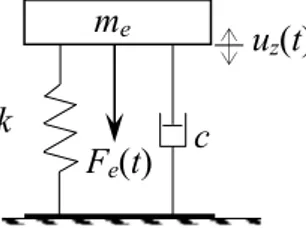
Fig. 2. A single degree of freedom model used to model
the investigated electrostatic resonators
To drive the oscillator at resonance, such as in mass sensing applications, a harmonic load vibrates the cantilever. To use a paddle cantilever in mass sensing application, the eigenfrequency of beam need to be accurately determined. The eigenfrequency is equal to fundamental resonance frequency of an oscillating cantilever if the elastic properties of the cantilever remain unchanged during the mass absorption process and the beam oscillates around its initial position.
A single degree of freedom model is used to simulate the dynamic response of the oscillator as presented in figure 2. In this model the proof mass of the cantilever is modeled as a lumped mass me, and its stiffness is considered as a spring constant k. If a voltage V(t) is applied between oscillator electrodes, the electrostatic force applied on the structure has a harmonic component with a frequency ω such as
2 0 2 )] ( [ 2 ) ( ) ( t u g t AV t F z e − = ε (1)
where ε is the permittivity of the free space, A=(w1×l1)+( w2×l2) is the effective area of the
capacitor, g0 is the initial gap between flexible plate and substrate, and uz(t) is the displacement of the mobile plate.
The fundamental resonant frequency of an electrostatically actuated cantilever can be computed as: e m k π ω 2 1 0= (2)
where me, the equivalent mass of system and k is the beam stiffness.
The stiffness of a paddle cantilever can be computed using the Castigliano’s second theorem as [3]: )] 3 3 ( [ 4 213 12 12 12 22 2 1 3 l l l l l w l w w w Et k + + + = (3)
where w1, w2, l1, l2, t are geometrical
dimensions of sample conforming to figure 1 and E is modulus of elasticity.
The equivalent mass can be calculated as [3]:
6 2 1 ) ( 140 ] [ l l t me + + + + = ρ β α γ θ (4)
where ρ is the density of material, and
7 2 2 6 2 1 2 1 5 2 2 1 2 1 4 2 3 2 1 2 2 2 1 2 3 1 4 1 3 1 1 33 ) 13 20 ( 7 ) 10 ( 63 ) 1155 1155 693 231 33 ( l w l l w w l l w w l l l l l l l l l w = + = + = + + + + = θ γ α β
The forced response of a mechanical oscillator determines the resonant frequency in either the presence or the absence of damping under the action of a harmonic excitation. In mechanical oscillators, the phenomenon of resonance is important, and in such situation the excitation frequency matches the resonant frequency of the system. The dynamic response of paddle cantilever oscillators subjected to a harmonic electrostatic force Fe(t) with the
c k me u z(t) Fe(t) z g0 t Lower electrode Cantilever x l1 y w2 w1 l2 Sensing plate Flexible plate Anchor
driving frequency ω given by an AC voltage is described by the equation of motion:
) ( ) ( ) ( ) ( . .. t F t u k t u c t u m⋅ z + ⋅ z + ⋅ z = e (5)
where c is the damping factor and m is the effective mass of beam.
The amplitude of oscillations under AC actuation can be written as:
2 0 2 2 0 2 1 ) ( ⎟⎟ ⎠ ⎞ ⎜⎜ ⎝ ⎛ + ⎟ ⎟ ⎠ ⎞ ⎜ ⎜ ⎝ ⎛ ⎟⎟ ⎠ ⎞ ⎜⎜ ⎝ ⎛ − = ω ω ξ ω ω z z t u u (6)
where ξ=c/(2mω0)is the damping ratio and uz
is the static deflection of cantilever.
The damping ratio ξ is any positive real number. For value of the damping ratio 0 ≤ ξ <1, the system has an oscillatory response. The system damping controls the amplitude of the response when excited at resonance. When the driving frequency equals the resonant frequency ω = ω0, the amplitude ratio reaches a maximum value. At resonance, the amplitude ratio becomes: ξ 2 1 ) ( = z z u t u (7)
An important qualifier of mechanical micro-oscillators is the quality factor Q. The Q- factor is a figure of merit that takes into consideration the various energies loses in a vibrating system, which, for a harmonic oscillator, is defined as:
d s U U
Q=2π (8)
where Us is the energy stored and Ud is the energy dissipated during one cycle of oscillation. At resonance, the quality factor is expressed as [4]: ξ 2 1 = r Q (9)
and the normalized response given by equation (7) is exactly the equal to Qr.
3. EXPERIMENTAL INVESTIGATIONS
The aims of experimental investigations are to determine the influence of the geometrical dimensions and the effect of operating conditions on the frequency response of electrostatically actuated paddle cantilevers. For experimental investigations a vibrometer analyzer is used and a white noises as an exciting signal.
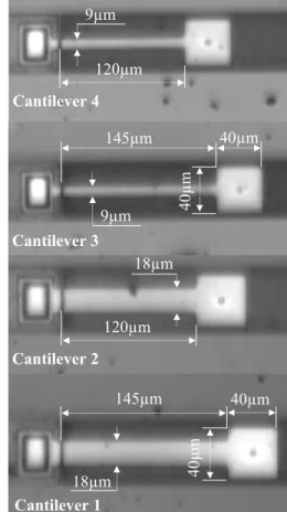
Fig. 3. Paddle cantilevers for experimental tests.
Figure 3 shows the samples for experimental investigations. These are microcantilevers fabricated from polysilicon with different positions of the sensing plate. The dimensions of sensing plate are 40µm by 40µm. The thickness of beams is 1.9µm and the gap between flexible part and substrate is 2µm.
During experimental tests peak amplitude of the driving signal of 3V are applied to oscillate the samples and their frequency responses are monitored. The changes in the frequency responses of cantilevers if the position of the sensing plate is moved toward to the beam anchor are experimentally determined under ambient conditions and in vacuum.
120µm 9µm 145µm 40µm 40µ m 40µm 40µ m 145µm 18µm Cantilever 1 Cantilever 2 Cantilever 3 120µm Cantilever 4 9µm 18µm
(a)
(b)
(c)
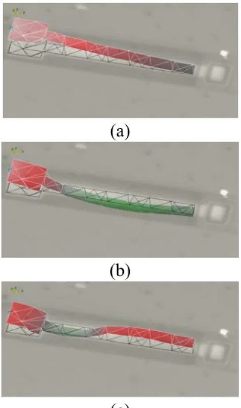
Fig. 4. Electrostatically actuated cantilever 1 under: (a)
the first bending mode, (b) the second bending mode and (c) the third bending mode of oscillations
Different vibration modes of cantilevers can be visualized and analyzed. Figure 4 shows the bending modes of the cantilever 1 from figure 3 under 3V the peak amplitude of AC signal. For this cantilever, the first bending mode of oscillation corresponding to a resonant frequency of 56.3kHz is presented in figure 4a. The second mode of vibration is shown in figure 4b and it corresponds to 292.19kHz. The third bending mode is presented in figure 4c for a resonant frequency of 946.56kHz.
In order, to estimate the effect of sensing plate positions on the dynamical response of investigated beams, only the changes in the first bending mode of vibrations were monitored and analyzed. The input signal is the same for all samples: 3V peak to peak amplitude of AC current. The experiments were repeated 5 times for each sample and the average results are presented and discussed. Figures 5 and 6 present the frequency responses of the investigated cantilevers tested under ambient conditions and in vacuum. As figures show, if the length of flexible part of beam decreases from 145µm to 120µm the resonant frequencies increase about 24%. Velocities of oscillations are influenced by the operating conditions based on the damping effect.
0 5 10 15 20 10 20 30 40 50 60 70 80 90 100 110 120 130 140 150 Resonant Frequency [kHz] V elo ci ty [µ m/s] Cant 2: RF = 73.8 kHz Cant 1: RF = 56.2 kHz Cant 3: RF = 40.84 kHz Cant 4: RF = 53 kHz
Fig. 5. Resonant frequency responses of the
investigated cantilevers tested in ambient conditions
0 1 2 3 4 5 6 7 8 30 40 50 60 70 80 90 Resonant Frequency [kHz] V el oc ity [mm /s] Cant 1: RF= 56.3 kHz Cant 2: RF= 74 kHz Cant 4: RF= 53.6 kHz Cant 3: RF= 40.84 kHz
Fig. 6. Resonant frequency responses of the investigated
cantilevers tested in vacuum (8×10⁻⁴mbar)
Additionally, the variation of the resonant Q-factor for investigated cantilevers tested in ambient conditions are experimental monitored. Based on the frequency response experimental curves, the quality factor can be determined as:
1 2 ω ω ω − = r Q (10)
where (ω2 - ω1) is the frequency bandwidth
corresponding to (0.707×Vmax).
For investigated cantilevers with a width of 18µm, increasing of the Q-factor from 0.82 for the cantilever 1 to 1.06 for the cantilever 2 is determined. The second set of cantilevers with a width of 9µm of the flexible plate, shows increasing of the Q-factor from 0.81 for cantilever 3 to 1.01 for cantilever 4. Using the values of Q-factors and based on equation (9) a shift of the damping ratio is observed as function of the sensing plate positions. The damping ratio decreases from 0.6 to 0.4 if the position of the sensing plate is moved toward to the beam anchor. As a consequence, the damping ratios is 0 ≤ ξ <1 which confirm that the cantilevers have oscillatory responses under the exciting signal.
4. FINITE ELEMENT ANALYSIS
a.
b.
c.
d.
Fig. 7. Modal analysis of: (a) cantilever 1,
(b) cantilever 2, (c) cantilever 3, (d) cantilever 4
To simulate the dynamic behaviour of investigated cantilevers and the change in the frequency response as function of the sensing plate position, finite element analysis is carried out using a commercial version of Oofelie Multiphysics Simulation Software.
The geometrical dimensions of cantilevers used in FEA are the dimensions of samples from experimental investigations.
The finite element analysis results of investigated cantilevers (Fig. 7) and their comparison with theoretical and experimental results are presented in table 1.
Table 1
Frequency responses of investigated cantilevers.
Samples Results FEA Exp. Th. Cantilever 1 55,29 56,3 55,5 Cantilever 2 72,47 74 72,8 Cantilever 3 41,19 40,84 41,3 Cantilever 4 52,50 53,6 53,65
5. PADLLE CANTILEVER USED IN MASS SENSING APPLICATIONS
The use of the paddle cantilever in mass sensing applications by monitoring its change in resonant frequency response implies: a) to measure initial resonant frequency ω0; b) to
measure the resonant frequency ω1 of
cantilever after mass absorption; c) to estimate the added mass Δm as:
⎟ ⎟ ⎠ ⎞ ⎜ ⎜ ⎝ ⎛ − = Δ 2 0 2 1 2 1 1 4π ω ω k m (11)
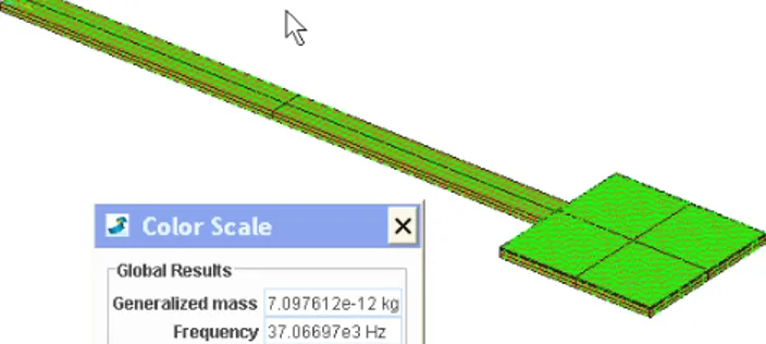
To exemplify the application of a paddle cantilever in mass sensing finite element analysis is carried out considering a thin film of 50nm thick, deposited on the sensing plate of the cantilever 3 with initial resonant frequency of 41.19 kHz (Fig.7c).
Fig. 8. Modal analysis of the investigated paddle
The resonant frequency of cantilever 3 after mass deposition is computed of 37.066 kHz (Fig.8). Using equation (11) the added mass is determined of 1.54ng. A mass sensitivity (Δω/Δm) of 2.6 kHz/ng for the cantilever 3 is estimated.
6. CONCLUSIONS
The paddle cantilevers can be used satisfactory in mass sensing application by monitoring their changes in the frequency responses. The sensitivity of cantilevers depends by the geometrical dimensions of samples. In order, to increase the sensitivity, cantilevers with high length and small width are recommended to be used. The testing conditions have influences on the minimum detectable mass. If the applications allow to be performed in vacuum, the sensitivity increases and the accuracy of measurements is improved. The experimental and finite element analysis results of frequency response are in good agreement of the investigated beams. The differences between results are influenced by the accuracy of experimental test and by the difference between material properties. In finite element analysis theoretical value of Young’s modulus (taken from literature) is used.
7. REFERENCES
[1] Boltshauser, T., Schonholzer, M., Brand, O., Baltes, H., Resonant humidity sensor using industrial CMOS-technology combined with postprocessing, J. Micromech. Microeng. 2, ISSN 0960-1317, 1992.
[2] Prescesky, S., Parameswaran, M., Rawicz, A., Turner, R., Reichl, U., Silicon- micromachining technology for sub-nanogram, discrete-mass, resonant biosensors, Can. J. Phys. 70, ISSN 0008-4204, 1992.
[3] Lobontiu, N., Dynamics of Microelectromechanical System, ISBN 978-0-387-36800-9, 2007, Springer Science, New York.
[4] Pustan, M., Paquay, S., Rochus, V., Golinval, JC., Effects of the electrode positions on the dynamical behaviour of electrostatically actuated MEMS resonators, Proceedings of the 12th Int. Conf. on Thermal, Mechanic, Multiphysic Simulation and Experiments in Microelectronics and Microsystems, ISBN 978-1-4577-0105-4, Linz, April 2011, IEEE, USA
INVESTIGAŢII DINAMICE LA CONSOLE MEMS DE TIP PALETA UTILIZATE IN APLICATII DE DETECTAREA MASEI
În acest articol, comportarea dinamica a consolelor MEMS de tip paleta actionate electrostatic este analizata cu scopul de a determina influentele pe care le au dimensiunile geometrice si conditiile de lucru asupra frecventei de raspuns la cantilevere fabricate din polysilicon. Analiza teoretica si cu elemente finite este realizata considerand cuplarea multi-fizica dintre domeniul electric si cel mecanic. Experimentele sunt realizate in mediul ambiant si in vacuum cu scopul de a identifica influenta pe care o are conditiile de operare asupra frecventei de raspuns a acestor cantilevere.
Marius Pustan, PhD., Associate Professor, Technical University of Cluj-Napoca, Department of Machine Elements and Tribology, Marius.Pustan@omt.utcluj.ro, +40264401665, Al. Peana 19/10, Cluj-Napoca, Romania, +40264571762.
Ovidiu Belcin, PhD., Professor, Technical University of Cluj-Napoca, Department of Machine Elements and Tribology, Ovidiu.Belcin@omt.utcluj.ro, +40264267388, Somesului 17, Floresti, Cluj-Napoca, Romania.
Jean-Claude Golinval, PhD., Professor, Faculty of Applied Science, Department of Aerospace and Mechanical Engineering, jc.golinvel@ulg.ac.be, +3243669177, Chemin des Chevreuils 1, 4000 Liège, Belgium.