I
January 2009
10
Wind Turbines -
Challenges and Innovative Solution
Procedures for Advanced Modelling
Bruyneel M.
1, Granville D.
1, Heege A.
2and Hemmelmann J.
31SAMTECH Headquarters, Liège, Belgium • 2SAMTECH Iberica, Barcelona, Spain • 3General Electric Global Research, Munchen, Germany
F
or centuries, people have used the power of wind for sailing ships, milling grain and pumping water. More recently, wind turbine technology has enabled us to harness wind to generate electricity. Today, wind power is one of the world’s fastest growing energy sources. The wind industry continues to expand and must develop larger, more reliable and more efficient wind turbines. Building a highly reliable wind turbine is a big challenge. Wind turbines are large flexible structures submitted to aerodynamic transient excitations. These dynamic loads may result in significant mechanical problems, sometimes with dramatic consequences such as failure of gear pinions and bearings and other components resulting from underestimated dynamic loading and related fatigue. There is clearly a need for simulation tools capable of accurately modelling the integral wind turbine behaviour.An innovative solution procedure is presented here for the accurate modelling of the dynamics of wind turbines. Based on a general finite element approach applicable to flexible multi-body systems, it is used at an industrial level and efficient for global and local (detailed) analyses. The results obtained were compared to experiments and showed good correlation.
Challenges in Wind
Turbine design
One of the important design challenges concerns the dynamic behavior of the entire wind turbine system. As reported in many papers [1], reports [2] and websites [3], the wind energy industry has experienced a lot of failures in the power train and bearings, observed after a couple of years of successful operation, a long way short of the design life goal of 20 years. The rotor shaft of a wind turbine is the place where all the forces and moments induced by the wind act. Peak loads, sudden loading reversal, emergency stop, changing wind direction, vibrations: each event contributes to a highly dynamic effect, far different from a classical design approach where static conditions are assumed. Accurate dynamic gearbox loads must therefore be evaluated. As it is included in a complex system (i.e. the entire wind turbine, with all its flexible components, its joints and its control system), analyzing a standalone gearbox is clearly of limited value. The resulting dynamic loads must rather be estimated considering the whole mechatronical system that is the mechanical system
and its control devices. Hence there is a need for global dynamic wind turbine models, even when local designs are addressed. On the other hand, using large scale finite element models would lead to excessive computing time, given the large number of load cases that must be taken into account in the analysis. As a result, model reduction techniques and specific dedicated elements must be available for developing practicable and realistic models of wind turbines.
Over the past 20 years, the size of the wind turbine rotor has significantly increased [4], simply because it is linked to the power generated (power proportional to diameter squared). It is believed that this tendency will continue in the future. Flexibility and non linear effects will then be more and more predominant in the analysis. Some current model simplifications, such as rigid parts or linear Super Elements, will become questionable in the future, when designing the components of a very large wind turbine. As already demonstrated elsewhere [5], neglecting the flexibility of the components and the joints of a virtual prototype leads to damping of medium and high vibrations
frequencies that should not be neglected in the design process. Thus there is a need for a flexible multi-body system solution, based on a general finite element approach, which is also able to include local flexible non linear detailed parts.
Together with an improvement in its power generation, increasing the size of the rotor leads to an increase of the mass (structural mass is nearly proportional to diameter cubed, [4]). As reported in [6] and explained earlier in the article, this growth in size complicates the detailed structural design and analysis techniques. Moreover, structural optimization techniques will certainly become essential to design the components of wind turbines with minimum weight and costs, and maximum performances [6], by improvement of the blades design, the selection of (composite) materials and the drive train concepts [7]. Experts in both the structural analysis and structural optimization fields will then have to work closely together, in order to design optimal wind turbines based on realistic parameterized (local and global) models.
January 2009
I
11
“
”
...there is a need for global dynamic wind turbine
models, even when local designs are addressed
Figure 1. Constant growth in rotor size and influence on the power generation (After [4,8])
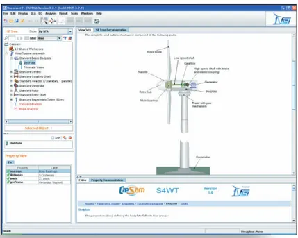
Figure 2. The components of a wind turbine and the model in the S4WT environment
The UpWind European project
It is clear that the research effort in this field is significant. UpWind [9] is a European project funded by the EU’s Sixth Framework Program, which started in March 2006 and will last until 2011. Bearing in mind the current and future challenges described above, the goal of UpWind is to develop tools and component concepts for the large wind turbines of tomorrow. The project covers all the fields involved in the design of a wind turbine: amongst these we can cite metrology for measuring fluctuating wind speed, innovative blade design and manufacturing, power electronics for the drive train, rotor blades and rotor control, costs analyses, aerodynamics, electric grid connection issues, and integral design approach methodologies. This last point is discussed below.
Global dynamic model
In terms of reliability, the drive train is one of the critical parts of modern wind turbines. Gearboxes and bearings are subjected to failures, resulting from insufficient calculation of the complex dynamic forces acting on the drive train. As it is a part of a system, and therefore interacts with the other components and the control devices, a model based on a standalone gearbox is certainly too poor to derive the accurate loading necessary for the design.
Here we explain how global and realistic models of a wind turbine can accurately estimate the forces acting on the power train. The models are developed with the SAMCEF finite element code and run in a unique dedicated environment called S4WT – SAMCEF for Wind Turbines [10]. Several ingredients must be present to produce a realistic and reliable model to compute the wind turbine drive train loads. Those loads can be associated with excitations induced by aerodynamic rotor blade loads and electromagnetic generator torque. On top of that, the proper dynamics of the entire dynamic system, including all control mechanisms must be considered as well. As a consequence a coupled aerodynamic-mechanical approach is recommended, as explained hereafter.
“
”
…the proper dynamics of the entire
dynamic system, including all control
mechanisms must be considered.
I
October 2008
12
Figure 3. Some details of a model including rigid and Super Elements, and the gearbox model
Figure 4. Three rotor support concepts studied with S4WT [7]
Flexible Multi-Body Dynamics with a Finite Element
Approach
The applied mathematical approach is based on a non-linear Finite Element formulation, which accounts for flexible Multi-Body-System functionalities [11], control devices and aerodynamics in terms of the Blade Element Momentum Theory simultaneously. The finite element approach has been extended to take relations between degrees of freedom into account, to make a motion useful for the desired purpose, that is, to handle kinematical constraints as in an MBS code [11]. This general formulation is coupled with Newmark and HHT time integration schemes. Although this approach is able to model (simple) classical problems of (rigid) multi-body systems and to solve them for a very short time, it is very general and also reliable for modelling complex virtual prototypes including rigid elements, Super Elements and full finite elements components. In practice such different modelling assumptions are mixed in the full wind turbine model.
Besides structural and mechanisms elements, some specific elements such as flexible bearings are used, which allow the production of light but very accurate models of complex gearboxes with important characteristics such as flexibility and clearance (Figure 3).
Parametric Models
In order to test different configurations or to include the wind turbine model in an optimization loop, it is important to develop parameterized models. Most common wind turbine concepts should be predefined in terms of parametric models. An example is provided in Figure 4, where parametric SAMCEF models of most common rotor support and power train concepts are presented and studied in [7]. The rotor might be supported by classical 3 suspension points in terms of 1 main bearing and planetary gearbox, or respectively by alternative concepts like 4 suspension points in terms of 2 main bearings, or the fixed axle concept. In the fixed axle concept, the rotor hub is supported by 2 main bearings and loads are transferred directly to the bedplate. All
January 2009
I
13
Figure 5. Modeling of blades by Super Elements and aerodynamic blade section elements
common gearbox layouts (for example 1 planetary stage & 2 parallel helical stages or 2 planetary stages & 1 parallel helical stage) can be used (Figure 4).
Computational Schemes
Dynamic analysis simulating the wind turbine behavior for different wind definitions, start-up and E-stop (i.e. emergency stop), or grid failure are clearly relevant analyses available in the developed tool. Moreover, fatigue life computation [13], specific waterfalls and Campbell diagrams are available. Additionally, linearized modal analysis can be performed at any time of the transient dynamic analysis. This is of course important to check the modal content for different configurations of the wind turbine and to produce linearized models that can be exported (e.g. to Matlab/Simulink).
Aerodynamic Analysis
An aero element is used for the computation of the aerodynamic loads on the blades. Typically, blades are discretized in a given number of sections, each provided with aerodynamic, geometric, elastic and mechanical properties. This specific element implements the Blade Element Momentum theory accounting for the actual wind field coming from a turbulent model, the tower shadow effect, the shear effect of the wind near the ground and the induction due to the interaction with blades (Figure 5).
Modeling of the Control System
The active systems of the wind turbines are modeled using control boxes, either defined internally or imported from a functional simulation tool such as Matlab/Simulink. Control boxes are connected to the mechanical model through sensors and actuators elements measuring and actuating kinematical information, such as distances, relative rotations, etc.
Application
The following validation of numerical results against experimental measurement concerns an E-stop simulation [14].
E-stop is the process that brings the wind turbine to rest as fast as possible. The control system orders an E-stop in the case of grid loss, excessive vibrations etc. In the example presented, the E-stop is triggered by a “grid loss” event which is characterized by a sudden drop in generator torque due to an electrical failure. As a consequence, the pretension of the power train is lost and large dynamic oscillations occur. These oscillations frequently produce backlashes.
Preventative measures, such as immediate pitching and activation of the disc brake, must be taken in order to ensure the wind turbine does not run into excessive over speed.
Aerodynamic results of the “emergency stop” are first obtained for a mean wind speed of 7 m/s with turbulence intensities according to IEC 61400-1 standard [12], i.e. a turbulence intensity of 24 % in the incoming wind direction. Turbulence intensities in lateral and vertical directions are 19% and 12% respectively.
Figure 6 presents the rotor shaft torque, the blade pitch angles, the speed of high speed shaft, the disc brake pressure and finally the electrical power. Note that the rotor shaft torque, generator speed and electrical power refer to the left ordinate and that the pitch angle plots refer to the right ordinate of Figure 6. As shown in this figure, the electrical power drops at 154s, and 0.4s later the full pressure of the disk brake is applied. Until this instance the blade pitch is nearly constant around 0 degrees, but in the following 14s, in order to invert the rotor torque, the blade is pitched into 90 degrees position, out of the rotor plane and into the wind. At
“
”
…blades are discretized in
a given number of sections,
each provided with aerodynamic,
I
Ocotber 2008
14
163.5s the generator rotation is fully stopped and from there the remaining kinetic energy of the rotor oscillates around the stand still position. The small time delays which are visible when the rotor torque crosses the zero torque line indicate the gearbox backlash.
Figure 7 shows the movements of the gearbox, measured at the torque arm bushings. As indicated in Figure 7, there are clearly visible vibrations at frequencies of 1p and 3p (where p is a frequency representing the rotor speed). The so called tower shadow effect is strongly visible in terms of frequency 3p, i.e. aerodynamic interaction of 3 rotating blades and the modification of wind field generated by the tower shadow. Taking into account that some small differences in blade pitch angle of each of the 3 blades is unavoidable, the numerical model accounts for an individual blade pitch error of 0.1 degrees. That misalignment of one individual blade pitch produces an excitation of frequency 1p, clearly visible in Figure 7. Due to the resulting unbalance of the aerodynamic forces acting at the rotor, the main shaft experiences a bending torque rotating along with rotor speed (1p), which finally leads to a deflection of the gearbox. As it can be seen in the graph, left and right fixing points of the gearbox move with a phase lag of 180 degrees, which indicates that the gearbox actually performs some kind of orbital movement due to the rotating bending moment. Similar behavior can be observed for the tower shadow excitation, which leads to 3p movement of the gearbox.
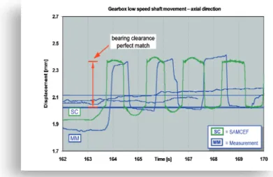
Figure 8 shows the axial oscillations of the so-called low speed shaft, which is the sun gear shaft of the first planetary gear stage, and shows that axially oscillations of the low speed shaft are reproduced very well by numerical simulation. Those axial movements are occurring during torque reversal, when the axial forces of the helical gears are reversed. In this situation the prevailing axial bearing clearances are overcome and the shaft moves from the left end position to the right end position. Analysis of such dynamic behavior can help to identify appropriate design solutions for the components.
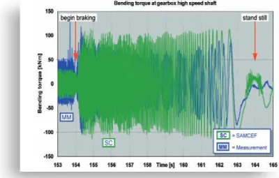
Finally, Figure 9 shows the bending moment measured at the exit of the gearbox high speed shaft. Note that the location for experimental data measurement and numerical data output are slightly different and as a consequence the amplitudes of bending moments show some differences. Obviously the bending torque increases during the brake event, which is a consequence of the high torque of the rotor shaft. According to Figure 6 the peak torque in the drive train rises up to about two times of the nominal torque during the E-stop event.
Conclusions
The implicit dependency of “power train loads” on the dynamic characteristics of the assembled wind turbine, excludes a decoupling of analysis techniques, in order to reduce the complexity of the numerical models. If a gearbox is analyzed without accounting for the other structural and aero-elastic properties of the wind turbine, there is a clear risk
Figure 6: Emergency stop simulation: comparison of experimental data and S4WT results. Presented data: pitch angle, generator speed, brake pressure, power.
Figure 7: Emergency stop simulation: comparison of experimental data and S4WT results. Presented data: gearbox movement at torque arm bushings.
Figure 8: Emergency stop simulation: comparison of experimental data and S4WT results. Presented data: gearbox low speed shaft movement.
January 2009
I
15
“
”
Analysis of such
dynamic behavior
can help to identify
appropriate design
solutions for the
components.
Figure 9: Emergency stop simulation: comparison of experimental data and S4WT results. Presented data: gearbox high speed shaft: bending moment.
that cycle count and load amplitudes are underestimated.
Operation deflection modes might affect the alignment of the power train and should be taken into account in fatigue evaluations. In that context it is essential to recognize that the load amplifications within the gearbox are generally much larger than the amplifications which would be detected by experimental measurement or numerical simulation at rotor shaft and/or generator shaft.
Numerical results of a wind turbine model of the mega-watt class were compared to experimental measurements. In particular, measurements were compared to numerical results for specific manoeuvres like “grid loss” events, “emergency stops” and operation under turbulent wind conditions.
The type of transients which were compared were: rotor and high speed shaft torques, deformations in the gearbox torque arm bushings, gearbox shaft displacements and loads, as well as global accelerations at specific locations like the tower top and further locations on the bedplate. For the cases which were investigated, wind turbine models could be tuned so that the differences between numerical results and available experimental data showed were generally less than 20%.
Contact
HEMMELMANN Jan [email protected] HEEGE Andreas [email protected] GRANVILLE Didier [email protected] BRUYNEEL Michaël [email protected]References
[1] Tavner P.J., Spinato F., Van Brussel G. and Koutoulakos E. (2008). “Reliability of different wind turbine concepts with relevance to offshore application”, European Wind Energy Conference – EWEC 2008, Brussels, Belgium, March 31 – April 3, 2008. http://www.supergen-wind.org.uk/docs/TavnerEtAl_2008_ReliabilityofDifferentWindTurbineC oncepts_EWEC2008.pdf
[2] BERR Department for Business Enterprise & Regulatory Reform (2005). “Capital Grant Scheme for offshore wind”, Annual Report, January – December 2005. Available at: http://www.berr.gov.uk/files/file34791.pdf [3] The Register (2008). “Disintegrating wind turbine caught on camera”,
http://www.theregister.co.uk/2008/02/27/disintegrating_turbine/ [4] Thresher R., and Laxson A. (2006). “Advanced wind technology: new
challenges for a new century”, European Wind Energy Conference – EWEC 2006, Athens, Greece, February 27 – March 2, 2006. Available at: http://www.nrel.gov/wind/pdfs/39537.pdf
[5] Bruyneel M. and Granville D. (2007). “Mechatronic analysis of a flexible mechanism using SAMCEF: application to robotics”, NAFEMS Seminar: FEA Modelling and Numerical Simulation – Advances and Practical Applications, October 24-25, 2007, Copenhagen, Denmark. http://www.aees.be/fsaero/cursus/1st_Quadrimestre/Cinemat/Bruyneel_ Granville_NAFEMS_Cop2007.pdf
[6] Tadish J.K., Wedel-Heinen J. and Petersen P. (2005). “New guidance for the development of wind turbine blades”, Copenhagen Offshore Wind Conference, 26-28 October, 2005, Copenhagen, Denmark. Available at: http://www.wmc.eu/public_docs/10316_000.pdf
[7] Heege A., Prats P., Betran J., Bastard L., Santos R. and Castell D. (2007). “Impact of wind turbine drive train concepts on dynamic gearbox loads”, European Wind Energy Conference – EWEC 2007 – Poster Session, Milan, Italy, 7-10 May 2007.
[8] European Commission (2005). “European wind energy at the dawn of the 21st century”.
http://ec.europa.eu/research/energy/pdf/eu_wind_energy_en.pdf [9] UPWIND European Project – http://www.upwind.eu
[10] Hegge A., Betran J. and Radovcic Y. (2007). “Fatigue load computation of wind turbine gearboxes by coupled finite element, multi-body system and aerodynamic analysis”, Wind Energy, 10 (5), pp. 395-413. [11] Géradin M. and Cardona A. (2001). “Flexible Multibody Dynamics: a
Finite Element Approach”, John Wiley & Sons.
[12] International Electrotechnical Commission (1997).”IEC 61400-1: Wind Turbine Generator Systems – Part 1: Safety Requirements”, 2nd Edition, IEC, Geneva, Switzerland.
[13] Hegge A. (2008). “Computation of fatigue load spectra of wind turbine gearboxes by coupled finite element, multi-body-system and aerodynamic analysis”, European Wind Energy Conference – EWEC 2008 – Poster Session, Brussels, Belgium, March 31 – April 3, 2008. [14] Hemmelmann J. (2008). “Transmission & conversion – workpackage
activities and first findings”, EWEC 2008 Session BW2 “UPWIND”, 1st April 2008. Available at: www.upwind.eu