Published in: Synthetic metals (1999), vol. 101, iss. 1-3, pp. 3-4 Status: Postprint (Author’s version)
Electrosynthesis of polyacrylic/polypyrrole composites: formation of
polypyrrole wires
Jérôme C, Labaye D, Bodart I, Jérôme R
Centre for Education and Research on Macromolecules (CERM) University of Liège, B6, Sart-Tilman, B-4000 Liège, Belgium
Abstract
A new preparation method is reported for the synthesis of conducting polypyrrole nanowires. This two-step all-electrochemical method consists in the cathodic grafting of a thin polyacrylate film on a carbon electrode, which is then used as an anode for the electropolymerization of pyrrole. Scanning electron microscopy shows the formation of polypyrrole wires (diameter ~600 nm lenght ~300 µm) growing through holes in the polyacrylate precoating. The effect of the experimental conditions, such as nature of the grafted polymer, solvent, and electrode, on the wire formation is discussed.
Keywords: Electropolymerization, Polypyrrole, Nanowires 1. Introduction
Research on metal and semiconductor nanowires is a rapidly expanding field stimulated by the need for molecular conductors of nanometric dimensions. In this respect, several research groups are paying attention to the confinement of doped conducting polymers, such as polypyrrole (PPy), in appropriate porous structure [1], Quite recently, we have reported on a new electrochemical technique for the synthesis of PPy nanowires [2]. A carbon electrode is modified by the cathodic electrografting of a polyethylacrylate (PEA) film, which is then used as a template for the electrosynthesis of PPy. This paper deals with the dependence of the nanowire formation on experimental parameters, such as nature of the solvent, the electrografted polymer, and the electrode substrate.
2. Experimental technique
The first electropolymerization reaction consists in the electrografting of a polyacrylate precoat by scanning the potential down to -1.8V/Pt. According to previous works [3], acrylonitrile (AN) and ethylacrylate (EA) can be electrografted onto various substrates such as metals (Pt, Fe, Ni) and carbon, in dimethylformamide (DMF) added with tetraethyl ammonium perchlorate (TEAP.0.05M) as
conducting salt. These thin polyacrylate films have the unique property of being attached onto the electrode surface although they are formed in a good solvent for the polymer. The swelling of these films by DMF allows the coated electrode to be used as the anode for the electropolymerization of pyrrole. PPy is synthesized by chronopotentiometry under a constant current of +0.5mA/cm2 for a constant time of 500s in a DMF solution decimolar in Py and
0.05M in TEAP.
3. Results and discussion 3.1 Effect of the solvent
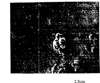
Pyrrole has been electropolymerized in DMF by the controlled polarization (250 mC) of a glassy carbon anode previously coated by an electrografted PEA film which is actually swollen by DMF. After careful washing by acetonitrile (ACN), the anode has been analyzed by SEM, and PPy wires has been observed to emerge from the grafted layer (thickness of the grafted film ~500 nm) (Fig. 1). These wires are randomly dispersed on the electrode surface, with diameter in the range of 400 nm to 1 µm and length of ca. 300 µm.
Published in: Synthetic metals (1999), vol. 101, iss. 1-3, pp. 3-4 Status: Postprint (Author’s version)
Fig. 1 Scanning electron micrograph of a PPy/ClO4 wire grown from a PEA grafted carbon electrode
It must be noted that PPy has a low conductivity when electropolymerized in DMF, i.e. a solvent of a high donor number (S ~5 x 10⁻⁴ S/cm [4]), compared to the conductivity observed when ACN is substituted for DMF (S ~80 S/cm [5]). So, the electropolymerization of Py has been repeated in ACN all the other conditions being kept unchanged (PEA grafted C electrode, TEAP 0.05M, Py 0.1M, I = 0.5 mA/cm2, t = 500 s). Figure 2 compares the chronopotentiograms observed in the two solvents for the same current density. The potential observed in ACN (Fig. 2B) is lower than in DMF (Fig. 2A), which indicates a better conductivity. However, no wire is observed by SEM for the sample prepared in ACN, but rather a PPy deposition that exhibits the cauliflower aspect usually observed in case of non previously coated anodes.
Fig. 2 Chronopotentiogram of PPy synthesis (I = 0.5 mA): A. in DMF onto PEA grafted C; B. in ACN onto PEA grafted C; C. in DMF onto PAN grafted C.
Since ACN and DMF are good solvents for PEA, the swelling of this grafted PEA film is expected to be comparable in the two solvents. The main solvent effect should concern the PPy conductivity. According to the proposed mechanism for the formation and growth of the PPy wire [2], we have to admit that in DMF, the PPy is not growing on itself but that the polymerization only occurs from the foot of the wire near the electrode surface. Wire formation actually indicates that Py cannot be oxidized on the surface of PPy that has grown through some holes in the electrografted PEA film. This
conclusion is consistent with the low conductivity of PPy formed in DMF [4], In contrast, the conducting properties of PPy are improved when formed in ACN, so that Py can be oxidized on the PPy surface leading accordingly to a three dimensional growth rather than to an unidimensional one. This tentative explanation of the solvent effect will be substantiated by extending the analysis to additional solvents (DMSO, PC,...).
Published in: Synthetic metals (1999), vol. 101, iss. 1-3, pp. 3-4 Status: Postprint (Author’s version)
3.2 Effect of the grafted polymer
The role of the grafted film on the formation of PPy wires has been studied by substituting a
thermoplastic PAN film for the soft PEA film used until now. Fig. 2C shows the chronopotentiogram observed when PPy is synthesized in DMF with a C anode previously grafted by PAN. The potential remains lower in DMF when the electrode is grafted by PAN rather than by PEA (Fig. 2A and 2C). The better coating properties of PEA is expected to limit the Py diffusion to the electrode surface in line with the overpotential observed at 1.8V for the first 200s in case of the grafted PEA film compared to a plateau at 1.33V when PAN is grafted onto the anode.
SEM observation of the PAN/PPy composite shows a nodular morphology for PPy (Fig. 3), which supports that the structural characteristics of the conducting polymer may be deeply affected by the insulating polymer which is pregrafted onto the electrode and acts as a template for the Py
polymerization.
Fig. 3 Scanning electron micrograph of PPy/ClO4 synthesized onto a PAN grafted C electrode.
3.3 Effect of the electrode substrate
Finally, the nature of the conducting substrate has been modified. PEA has been grafted onto Pt instead of glassy carbon. Since the Py polymerization requires an anodic potential, the use of metals prone to oxidation, such as Fe or Ni, is much less convenient. The chronopotentiogram (Fig. 2D) shows an initial overpotential at 2.3V that rapidly decreases down to a plateau value at 1.6V.
The morphology of the PPy formed on the Pt/PEA electrode is also nodular, and no wire is observed. The actual effect of the substrate on the morphology of PPy is unclear yet, and requires additional experiments before drawing definite conclusions.
4. Conclusion
PPy wires can grow from a PEA grafted carbon anode when Py is electropolymerized in DMF added with TEAP. Modification of experimental parameters, such as solvent (ACN instead of DMF), grafted polymer template (PAN rather than PEA), and electrode substrate (Pt instead of C) greatly affects the morphology of PPy which turns out to loose its unique capability of forming wires. A deeper analysis is required to understand the basic mechanism for the PPy wire formation.
Acknowledgements
CJ is grateful to the "Fonds de la Recherche pour l'Industrie et l'Agriculture" for a fellowship. The authors are indebted to the "Services Fédéaux des Affaires Scientifiques, Techniques et Culturelles" for support in the frame of the "Pôles d'Attractions Interuniversitaires: Supramolecular Catalysis and Supramolecular Chemistry"
Published in: Synthetic metals (1999), vol. 101, iss. 1-3, pp. 3-4 Status: Postprint (Author’s version)
5. References
[1] G.A. Ozin, Adv. Mater., 4 (1992) 612
[2] C. Jérôme, R. Jérôme, Angew. Chem., accepted May (1998)
[3] R. Jérôme, M. Mertens, L. Martinot, Adv. Mater. 7 (1995) 807 _ [4] J. Jianyang, Y. Li, Polymer 38 (1997)1.971